EP0704225A2 - Spritze mit zurückziehbarer Nadel - Google Patents
Spritze mit zurückziehbarer Nadel Download PDFInfo
- Publication number
- EP0704225A2 EP0704225A2 EP95306673A EP95306673A EP0704225A2 EP 0704225 A2 EP0704225 A2 EP 0704225A2 EP 95306673 A EP95306673 A EP 95306673A EP 95306673 A EP95306673 A EP 95306673A EP 0704225 A2 EP0704225 A2 EP 0704225A2
- Authority
- EP
- European Patent Office
- Prior art keywords
- plunger
- carrier
- barrel
- distal end
- projection
- Prior art date
- Legal status (The legal status is an assumption and is not a legal conclusion. Google has not performed a legal analysis and makes no representation as to the accuracy of the status listed.)
- Granted
Links
Images


Classifications
-
- A—HUMAN NECESSITIES
- A61—MEDICAL OR VETERINARY SCIENCE; HYGIENE
- A61M—DEVICES FOR INTRODUCING MEDIA INTO, OR ONTO, THE BODY; DEVICES FOR TRANSDUCING BODY MEDIA OR FOR TAKING MEDIA FROM THE BODY; DEVICES FOR PRODUCING OR ENDING SLEEP OR STUPOR
- A61M5/00—Devices for bringing media into the body in a subcutaneous, intra-vascular or intramuscular way; Accessories therefor, e.g. filling or cleaning devices, arm-rests
- A61M5/178—Syringes
- A61M5/31—Details
- A61M5/32—Needles; Details of needles pertaining to their connection with syringe or hub; Accessories for bringing the needle into, or holding the needle on, the body; Devices for protection of needles
- A61M5/3205—Apparatus for removing or disposing of used needles or syringes, e.g. containers; Means for protection against accidental injuries from used needles
- A61M5/321—Means for protection against accidental injuries by used needles
- A61M5/322—Retractable needles, i.e. disconnected from and withdrawn into the syringe barrel by the piston
-
- A—HUMAN NECESSITIES
- A61—MEDICAL OR VETERINARY SCIENCE; HYGIENE
- A61M—DEVICES FOR INTRODUCING MEDIA INTO, OR ONTO, THE BODY; DEVICES FOR TRANSDUCING BODY MEDIA OR FOR TAKING MEDIA FROM THE BODY; DEVICES FOR PRODUCING OR ENDING SLEEP OR STUPOR
- A61M5/00—Devices for bringing media into the body in a subcutaneous, intra-vascular or intramuscular way; Accessories therefor, e.g. filling or cleaning devices, arm-rests
- A61M5/178—Syringes
- A61M5/31—Details
- A61M5/32—Needles; Details of needles pertaining to their connection with syringe or hub; Accessories for bringing the needle into, or holding the needle on, the body; Devices for protection of needles
- A61M5/34—Constructions for connecting the needle, e.g. to syringe nozzle or needle hub
- A61M5/347—Constructions for connecting the needle, e.g. to syringe nozzle or needle hub rotatable, e.g. bayonet or screw
-
- A—HUMAN NECESSITIES
- A61—MEDICAL OR VETERINARY SCIENCE; HYGIENE
- A61M—DEVICES FOR INTRODUCING MEDIA INTO, OR ONTO, THE BODY; DEVICES FOR TRANSDUCING BODY MEDIA OR FOR TAKING MEDIA FROM THE BODY; DEVICES FOR PRODUCING OR ENDING SLEEP OR STUPOR
- A61M5/00—Devices for bringing media into the body in a subcutaneous, intra-vascular or intramuscular way; Accessories therefor, e.g. filling or cleaning devices, arm-rests
- A61M5/50—Devices for bringing media into the body in a subcutaneous, intra-vascular or intramuscular way; Accessories therefor, e.g. filling or cleaning devices, arm-rests having means for preventing re-use, or for indicating if defective, used, tampered with or unsterile
- A61M5/5013—Means for blocking the piston or the fluid passageway to prevent illegal refilling of a syringe
- A61M5/502—Means for blocking the piston or the fluid passageway to prevent illegal refilling of a syringe for blocking the piston
Definitions
- the present invention relates to hypodermic syringes. More particularly, the present invention relates to a syringe having structure for withdrawing the hypodermic needle into the syringe barrel after use.
- a syringe includes a cylindrical barrel commonly made of thermoplastic material or glass, having a distal end connected to a sharpened needle cannula and a proximal end adapted to receive a stopper and plunger assembly.
- a safety device contained within the syringe is activated to prevent further contact with the sharp needle tip.
- One type of safety syringe includes structure which allows the withdrawal of the hypodermic needle into the syringe barrel to minimize the chance of further contact with the sharp needle tip. A syringe with its needle withdrawn can be more safely transported to a disposal system.
- One such prior art retractable needle syringe includes a frangible zone which allows separation of the forward wall of the barrel, which is connected to the hypodermic needle, from the side wall of the barrel.
- the syringe also contains structure on the interior of the forward wall and the exterior of the piston for selectively attaching the piston to the forward wall so that the user can forcibly twist the piston to break the frangible means and draw the forward wall, including the hypodermic needle, into the syringe barrel.
- This design requires a compromise in the design of the syringe barrel.
- the barrel must be strong enough to remain intact during normal use yet weak enough to be sheared apart by any user regardless of strength.
- a retractable needle syringe of the present invention includes an elongate barrel having an inside surface defining a chamber, an open proximal end and a distal end.
- An elongate plunger is slidably positioned in fluid-tight engagement with the inside surface of the barrel.
- the plunger includes a distal end, a proximal end extending outwardly from the open end of the barrel, and a radially directed projection on the distal end of the plunger rod.
- a movable carrier is positioned in fluid-tight engagement with the inside surface of the barrel, the carrier includes an outside surface, a distal end, a proximal end, and a passageway therethrough in fluid communication with the chamber.
- the proximal end of the carrier includes an open-ended groove which is sized and shaped to receive the plunger projection.
- the groove includes an axial portion and a circumferential portion.
- the plunger is movable axially, distally and proximally, so that the plunger projection can enter and exit the axial portion of the groove Rotation of the plunger with respect to the carrier causes the projection to enter the circumferential portion of the groove containing or trapping said projection so that said plunger rod can apply axially directed force and rotationally directed force to the carrier.
- a needle cannula projects outwardly from the distal end of the carrier.
- the cannula includes a distal end, a proximal end and a lumen therethrough in fluid communication with the passageway of the carrier.
- Control structure is provided to prevent movement of the carrier with respect to the barrel during normal use of the syringe while the control means is in a first locked position, and the allowing the carrier to be moved proximally into the chamber of the barrel through forces applied to the plunger while the control means is in a second unlocked position. Transition between the first locked position and the second unlocked position and withdrawing the cannula into the barrel is accomplished by at least two motions of the plunger with respect to the barrel while the distal end of the plunger engages the carrier.
- the first motion is rotational to rotate the carrier with respect to the barrel through an acute angular rotation followed by a second axial motion proximally directed to move the carrier into the barrel far enough so that the distal end of the cannula does not extend beyond the distal end of the barrel.
- Fig. 1 is a perspective view of a preferred embodiment of the retractable needle syringe of the present invention.
- Fig. 2 is an exploded view showing the assembly of the syringe of Fig. 1.
- Fig. 3 is an enlarged partial view of Fig. 2 illustrating the distal end of the syringe barrel, the plunger rod and the carrier.
- Fig. 4 is a side elevation view of the distal end of the plunger of of Fig. 3.
- Fig. 5 is a side elevation view of the proximal end of the carrier of Fig. 3.
- Fig. 6 is a partial cross-sectional side elevation view of the syringe of Fig. 1 illustrating the position of the plunger as medication is being expelled from the syringe.
- Fig. 7 is the syringe of Fig. 6 illustrating the position of the plunger rod after medication has been expelled from the syringe.
- Fig. 8 is the syringe of Fig. 7 illustrating the locking of the plunger to the carrier.
- Fig. 9 is the syringe of Fig. 8 illustrating the unlocking of the carrier from the barrel.
- Fig. 10 is the syringe of Fig. 9 illustrating the needle carrier and the needle withdrawn into the barrel.
- Fig. 11 is the syringe of Fig. 10 wherein the needle carrier and needle are further withdrawn into the barrel to a locked position, and the proximal end of the plunger rod is broken off and removed from the distal end of the plunger rod.
- Fig. 12 is an alternative embodiment of the carrier and needle of the present invention.
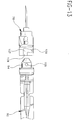
- Fig. 13 is an alternative embodiment of the carrier and plunger of the present invention.
- a retractable needle syringe assembly 20 includes an elongate barrel 21 having an inside surface 22 defining a chamber 23. Barrel 21 also includes an open proximal end 25 and a distal end 27.
- distal end is intended to refer to the end of the syringe from which the needle cannula projects
- proximal end is intended to refer to the end of the syringe closest to the holder of the syringe and furthest from the tip of the needle.
- a movable needle carrier 28 is positioned in fluid-tight engagement with inside surface 22 of barrel 21 at distal end 27.
- the needle carrier includes a distal end 29, a proximal end 31 and a passageway 32 therethrough in fluid communication with chamber 23.
- the carrier includes circumferential groove 33.
- Annular elastomer ring 34 is positioned in groove 33 and contacts the inside surface of the barrel to help provide a fluid-tight engagement between the inside surface of the barrel and the carrier.
- the elastomeric ring can have a variety of cross-sectional shapes, such as circular, rectangular, square and the like. It is within the purview of the present invention to include a carrier without an elastomeric ring.
- Such a carrier can be made of plastic and have an annular rib molded in its body.
- the annular rib can be shaped to be resilient.
- the annular rib could be rigid and a fluid-tight seal with the barrel can be achieved by relying on the resiliency of the barrel.
- the carrier can be mounted to the barrel through threaded structure on the outside of the carrier and the inside of the distal end of the barrel.
- a needle cannula 37 projects outwardly from distal end 29 of the carrier.
- Cannula 37 includes a distal end 38, a proximal end 39 and a lumen therethrough in fluid communication with passageway 32.
- the needle cannula in this embodiment includes sharpened distal tip 41 to facilitate use of the needle to pierce the skin for delivery of therapeutic liquids or the removal of bodily fluids such as blood.
- the needle is fixedly attached to the carrier.
- the present invention includes a plunger 42 slidably positioned in fluid-tight engagement with the inside surface of the barrel.
- plunger means includes an elongate plunger rod 43, having proximal end 44 and distal end 45, and an annular sealing ring 46 contained between distal sealing ring flange 47 and proximal sealing ring flange 49.
- Annular sealing ring 46 can have a variety of cross-sectional shapes, such as circular, rectangular, square and the like. The purpose of the sealing ring is to provide a fluid-tight engagement between the plunger and the barrel. It is within the scope of the present invention to include a plunger without a separate annular sealing ring.
- Such a plunger could be made entirely of plastic and have an annular rib molded around in the approximate position of the annular sealing ring 46 of the preferred embodiment.
- This rib would be integrally molded with the plunger and shaped to be resilient or deflectable to achieve the fluid-tight seal with the barrel.
- the annular rib could be formed to be relatively rigid and the barrel molded with a thin sidewall so that the fluid-tight seal is achieved through the deflection or resiliency of the barrel.
- the plunger rod is accessible outside of the proximal end of the barrel and is provided to move the sealing ring along the barrel to force fluid into and out of the chamber through the passageway.
- a plunger rod flange 50 is provided as a convenient structure for applying force to move the plunger rod with respect to the barrel.
- Barrel flange 51 is provided to assist the user in providing axial force between the plunger rod and the barrel.
- Engagement means is provided for allowing the distal end of the plunger rod to engage the carrier for allowing proximally directed forces and rotational forces applied to the plunger to be transmitted to the carrier.
- engagement means includes a radially directed projection 55 on distal end 45 of the plunger rod.
- the second radially directed projection is on the opposite side of the distal end of the plunger rod. Both projections will function in the same manner.
- Engagement means further includes an open-ended groove 57 on proximal end 31 of the needle carrier. Groove 57 is sized and shaped to receive plunger projection 55. Groove 57 includes an axial portion 58 and a circumferential portion 59.
- Proximal end 31 of the needle carrier includes recess 35 which is sized and shaped to receive the distal end of the plunger rod with minimal air space between the distal end of the plunger rod and the and the recess in the carrier.
- the plunger is movable axially, distally and proximally, so that the plunger projection 55 can enter and exit axial portion 58 of groove 57.
- Rotation of the plunger with respect to the carrier causes projection 55 to enter circumferential portion 59 of the groove wherein the groove contains the projection so that the plunger rod can be used to apply axial directed and rotationally directed force to the. carrier.
- a radial directed projection and a circumferential portion of the open-ended groove which are shaped to allow the projection to be positioned within the circumferential portion of the groove and removed from that portion, and subsequently reinserted and removed as manv times as desirable.
- these elements are designed for a single use. Specifically, when the plunger is advanced to its most distal position, expelling medication in the syringe, the plunger rod may be rotated clockwise, as best illustrated in Fig. 8, to cause radial directed projection 55 to enter circumferential portion 59.
- the projection and the circumferential portion of the open-ended groove are configured so that when the projection is positioned in the circumferential portion, the projection is locked in the circumferential portion and cannot be removed therefrom.
- the locking function is accomplished by having locking edges 56 on the projection which snap into and engage locking edges 60 of the circumferential portion, as best illustrated in Fig. 8. This feature prevents use of the syringe once projection 55 is locked into circumferential portion 59.
- Various shapes and configurations can be used for a projection which locks into the circumferential portion of the groove. Additional sheet metal fasteners may be used on the projection and/or in the groove to make a secure locking arrangement.
- Locking may also be accomplished through the use of encapsulated adhesive wherein the adhesive capsules are broken when the projection enters the circumferential portion of the groove. Also, it is within the purview of the present invention to have the projection extending radially inwardly from the recess in the carrier and have the groove formed on the distal end of the plunger. This embodiment would function in the same manner as described above with the projection moving from the plunger to the carrier and the groove moving from the carrier to the plunger.
- control means for helping prevent movement of the needle carrier with respect to the barrel when the control means is in a first locked position, and for allowing the carrier to be moved proximally into said chamber when the control means is in a second unlocked position.
- control means includes control groove 61 on outside surface 36 of the carrier. In this embodiment there are two control grooves, one on each side of the carrier. Each control groove includes a closed proximal end 62 and an open distal end 63.
- Inwardly directed projections 65 on the inside surface of the barrel are positioned within the grooves when the carrier is at the distal end of the barrel. In this embodiment, the projections are cylindrical having a circularly-shaped cross-section As illustrated in Figs.
- the projections prevent proximal and distal motion of the carrier with respect to the barrel when the projections are in closed ends 62 of control grooves 61. Accordingly, substantial axial force can be applied in a proximal or distal direction without forcing the carrier into the barrel or removing it from the barrel and rendering the syringe unusable.
- the distal end of the barrel may also have an inwardly projecting flange to resist distal motion of the carrier out of the barrel.
- each groove includes a restriction or area of reduced depth 67 adjacent to closed end 62.
- the area of restriction or reduce depth is shallower than the length of projection 65 so that additional rotational force is required to move the carrier into and out of a position where projections 65 are positioned at closed ends 62 of the grooves.
- the restriction in this invention can also be an area of reduced width in the groove adjacent to the closed end which is configured so that additional rotational force is required to move the carrier into and out of the position where projections 65 are positioned at closed ends 62 of the grooves.
- the syringe of the present invention can be used in the same manner as a conventional hypodermic syringe following known and accepted safe usage procedures.
- the user rotates the plunger clockwise with respect to the barrel, as illustrated in Fig. 8, so that the radial directed projection 55 on the distal end of the plunger rod enters circumferential portion 59 of open ended groove 57.
- the projection is now locked in the groove. Any attempt to unlock the projection will cause locking edges 56 on the projection to engage locking edges 60 in the open-ended groove. Accordingly, in a preferred embodiment, this step cannot be reversed.
- a major advantage of the present invention is that it can be configured to expel almost all of the medication in the chamber during the injection process because additional distal movement of the plunger rod is not necessary to secure the plunger rod to the needle carrier, only rotational force is required to accomplish this result.
- This preferred embodiment also includes means for aligning the plunger with respect to the barrel so that radial directed projection 55 on the plunger enters axial portion 58 of open ended groove 57 upon distally directed axial motion of the plunger only, without requiring the operator to rotate the plunger with respect to the barrel or the carrier.
- a substantial portion of the elongate plunger rod is formed of four longitudinal equally spaced ribs 52 having a plus-sign shaped cross-section. The space between two adjacent ribs functions as a longitudinal groove along the plunger rod. Rotation of the plunger rod with respect to the barrel can be prevented by providing an inwardly directed tab or projection in the barrel which projects into the groove or the space between the ribs 52.
- an inwardly directed tab is formed by molding said barrel with H-shaped gap 69 in the barrel wall resulting in cantilever tabs 70 being formed in the barrel wall.
- the cantilever tabs 70 are pressed inwardly through the use of pressure or pressure and heat to form inwardly projecting tabs as best illustrated in Fig. 10. These tabs prevent rotation of the plunger rod and can be used to align the plunger rod projection with the axial portion of the open-ended groove.
- Any inwardly directed projection, formed in the barrel or by a separate element attached to the barrel can be used to prevent retention of the plunger. After the projection enters the open-ended groove in the carrier it is not desirable to prevent rotation of the plunger rod.
- cutouts 71 are provided in the plunger rod to allow rotation of the plunger rod with respect to the barrel when the radially directed projection 55 is in open-ended groove 57. Rotation is allowed because the cutouts 71 are deeper than the projection distance of tab 70. As will be described in more detail hereinafter, tabs 70 also serve as a locking means to hold the plunger rod in the retracted position after the needle is withdrawn into the barrel.
- the user may then pull the plunger rod in a proximal direction with respect to the barrel, to draw the carrier and the needle into the barrel past the open distal end, as illustrated in Fig. 10.
- the syringe assembly may be safely delivered to a disposal container.
- the plunger rod contains an area of reduced thickness 53.
- the plunger rod may be withdrawn from the barrel to a position where the area of reduced thickness is outside of the barrel. At this point the plunger rod may be subjected to a bending force which will cause the proximal portion of the plunger rod to break from the distal portion of the plunger rod as illustrated in Fig. 11.
- This feature further renders the syringe assembly unusable and helps prevent accidental movement of the needle carrier in a distal direction to reexpose the sharp needle point.
- Another safety feature of the present invention is means for locking the plunger rod in the barrel after the needle cannula is retracted into the barrel.
- locking is accomplished through interaction of locking flange 54 on the plunger rod and inwardly projecting tabs 70 in the barrel.
- the user Upon withdrawing the needle carrier into the barrel, the user continues to pull the needle carrier in a proximal direction until locking flange 54 deflects tabs 70 and becomes trapped therebetween as best illustrated in Fig. 11.
- the plunger rod cannot move axially with respect to the barrel.
- the tabs which prevent rotation of the plunger rod are also the tabs which trap the locking flange. This does not have to be the case and separate structures can be provided for each means.
- Additional elements such as sheet metal structures may be attached to the barrel and/or the plunger to engage each other and lock the plunger rod with respect to the barrel.
- the plunger rod should be broken off after the locking mechanism is engaged so that the plunger rod will not come out of the barrel during attempts to break the plunger rod at the area of reduced thickness.
- the carrier may include a distal threaded projection which mates with a threaded portion in the barrel.
- the threads only function to connect the syringe barrel and the carrier and the function of the syringe with respect to moving the needle assembly and carrier into the barrel is exactly as described above except it is accomplished with more rotational motion of the plunger rod. With a threaded connection the threads should be in a direction to allow the user to rotate the carrier in the proper direction for unlocking.
- a wide variety of structures are capable of allowing the engagement of the carrier with the barrel, and those structures described hereinabove are representative of these many possibilities, which are within the purview of the present invention.
- Fig. 12 illustrates an alternative needle carrier of the present invention.
- the needle cannula is part of a needle assembly 73 which includes needle cannula 37 and hub 74.
- the needle hub and the needle carrier 72 contain cooperating structure so that the needle assembly is removably attached to the carrier.
- the needle hub includes a frusto-conically shaped interior structure adapted to frictionally engage a tapered luer tip 75 at the distal end of the carrier.
- projections 76 on the proximal end of the hub engage an internal helical groove 77 of the carrier so that rotation of the needle with respect to the carrier causes the projections to be drawn proximally along the helical groove to tighten and secure the frictional engagement of the tapered luer tip 75 with the frusto-conically shaped recess of hub 74.
- the needle assembly described herein is a known and commercially available needle assembly, designed to cooperate with syringes or other fittings having male locking luer-type fittings.
- the alternative carrier illustrated in Fig. 12 functions in the same manner and cooperates with the same plunger and syringe barrel as illustrated in the embodiment of Figs. 1-11.
- Fig. 13 illustrates an alternative needle carrier and plunger of the present invention.
- needle carrier 78 includes open ended groove 107 having an axial portion 108 and a circumferential portion 109.
- Plunger 92 includes distal end 94 having radially directed projection 105.
- the radially directed projection is circularly shaped.
- a slight proximal motion of the plunger with respect to the barrel to draw the fluid toward the chamber can be desirable, after the syringe has been used, to withdraw any fluid remaining in the lumen of the needle cannula back toward the chamber of the barrel, so that the fluid may not be accidentally discharged into the environment.
- This function can be accomplished by a slight proximal motion of the plunger with respect to the barrel to draw the fluid toward the chamber.
- the embodiment of Fig. 13 is designed to provide such proximal motion of the plunger with respect to the barrel.
- circumferential portion 109 of open ended groove 107 is directed proximally so that as radially directed projection 105 on plunger 92 enters circumferential potion 109, said plunger is forced to move in a proximal direction with respect to the barrel as radial directed projection moves along the circumferential portion which is proximally directed.
- the slight proximal motion of the plunger with respect to the barrel causes fluid in the needle cannula to be drawn toward or into the syringe barrel.
- the radially directed projection 105 is circularly shaped.
- the plunger and the carrier of the embodiment of Fig. 13 function in substantially the same way as the plunger and the carrier of the embodiment of Figs. 1-11.
- the barrel of the safety needle syringe of the present invention may be constructed of a wide variety of materials with thermoplastic and glass materials being preferred.
- Inwardly facing projections at the distal end of the barrel may be formed of the barrel material or be formed of additional components made of suitable rigid materials such as thermoplastic and corrosion resistant metal such as stainless steel.
- the plunger rod and the carrier of the present invention can be made through a wide variety of materials with thermoplastic materials such as polypropylene, polyethylene and polystyrene being desirable.
- thermoplastic materials such as polypropylene, polyethylene and polystyrene being desirable.
- a wide variety of material such as natural rubber, synthetic rubber and thermoplastic elastomers are suitable for forming the annular elastomeric ring and the annular sealing ring.
- the materials used for the components should be chosen to withstand the sterilization process utilized.
- the present invention provides a simple, straightforward, reliable, easily fabricated retractable needle syringe having locking structure for holding the needle in a position with respect to the barrel which is strong enough to resist the often substantial forces experienced during normal use and which is easily de-activated to lower the force required for withdrawing the needle into the barrel.
- the present invention provides a retractable needle syringe that does not waste medication by requiring additional axial motion of the plunger rod to secure the plunger rod to the needle carrier.
- the present invention also provides a one-way locking mechanism so that when the plunger rod is secured to the carrier it will not disconnect from the carrier; finally, when the needle is withdrawn inside the barrel there is a need for the locking mechanism to prevent the needle from being later moved so that it projects out of the barrel.
Landscapes
- Health & Medical Sciences (AREA)
- Engineering & Computer Science (AREA)
- Heart & Thoracic Surgery (AREA)
- Vascular Medicine (AREA)
- Anesthesiology (AREA)
- Biomedical Technology (AREA)
- Environmental & Geological Engineering (AREA)
- Hematology (AREA)
- Life Sciences & Earth Sciences (AREA)
- Animal Behavior & Ethology (AREA)
- General Health & Medical Sciences (AREA)
- Public Health (AREA)
- Veterinary Medicine (AREA)
- Infusion, Injection, And Reservoir Apparatuses (AREA)
Applications Claiming Priority (2)
| Application Number | Priority Date | Filing Date | Title |
|---|---|---|---|
| US314030 | 1981-10-22 | ||
| US08/314,030 US5533970A (en) | 1994-09-28 | 1994-09-28 | Retractable needle syringe |
Publications (3)
| Publication Number | Publication Date |
|---|---|
| EP0704225A2 true EP0704225A2 (de) | 1996-04-03 |
| EP0704225A3 EP0704225A3 (de) | 1996-06-26 |
| EP0704225B1 EP0704225B1 (de) | 1999-12-15 |
Family
ID=23218253
Family Applications (1)
| Application Number | Title | Priority Date | Filing Date |
|---|---|---|---|
| EP95306673A Expired - Lifetime EP0704225B1 (de) | 1994-09-28 | 1995-09-21 | Spritze mit zurückziehbarer Nadel |
Country Status (5)
| Country | Link |
|---|---|
| US (1) | US5533970A (de) |
| EP (1) | EP0704225B1 (de) |
| JP (1) | JPH08107931A (de) |
| CA (1) | CA2157564C (de) |
| DE (1) | DE69513920T2 (de) |
Cited By (20)
| Publication number | Priority date | Publication date | Assignee | Title |
|---|---|---|---|---|
| EP0818209A1 (de) * | 1995-08-22 | 1998-01-14 | Long-Hsiung Chen | Sicherheitssubkutanspritze für Kleindosierungen |
| EP0818211A1 (de) * | 1996-07-10 | 1998-01-14 | Long-Hsiung Chen | Vereinfachte Sicherheitsspritze mit einziehbarer selbstvorgespannter Nadel und mit minimiertem Kolben |
| WO1998020923A1 (en) * | 1996-11-15 | 1998-05-22 | Adventec, Inc. | Syringe with retractable needle assembly |
| WO2001080930A1 (en) | 2000-04-26 | 2001-11-01 | Unitract Pty Ltd | Single use syringe |
| EP1184049A1 (de) * | 2000-08-30 | 2002-03-06 | Becton, Dickinson and Company | Hypodermische Spritze mit selektiv zurückziehbarer Nadel |
| EP1216719A1 (de) * | 2000-12-21 | 2002-06-26 | Lin Wang | Sicherheitsspritze |
| EP1237601A4 (de) * | 1999-12-07 | 2003-01-22 | Mdc Invest Holdings Inc | Medizinsiche vorrichtung mit einer zurückziehbaren nadel |
| GB2380136A (en) * | 2001-10-01 | 2003-04-02 | Cosbin Invest Inc | Disposable Safety Syringe |
| US6706015B2 (en) * | 2002-05-07 | 2004-03-16 | Medexel Korea | Safety syringe |
| WO2005084734A1 (en) * | 2004-03-09 | 2005-09-15 | Advanced Protective Injection Systems (A.P.I.S.) B.V. | Injection syringe |
| US7329238B2 (en) | 1999-12-07 | 2008-02-12 | Specialized Health Products Inc. | Safety needle medical bearing devices |
| WO2008019034A1 (en) * | 2006-08-03 | 2008-02-14 | Becton, Dickinson And Company | Syringe and removable needle assembly having binary attachment features |
| WO2009091707A1 (en) * | 2008-01-15 | 2009-07-23 | Becton, Dickinson And Company | Medical injector with pen needle assembly |
| US7762994B2 (en) | 2002-07-03 | 2010-07-27 | Novo Nordisk A/S | Needle mounting system and a method for mounting a needle assembly |
| EP1608421A4 (de) * | 2003-03-20 | 2011-11-09 | Unitract Syringe Pty Ltd | Spritzenfederhalter |
| WO2012162821A1 (en) * | 2011-05-31 | 2012-12-06 | L.O.M. Laboratories Inc. | Modular gas-actuated retractable needle assembly |
| US8333739B2 (en) | 2000-06-16 | 2012-12-18 | Novo Nordisk A/S | Injection device |
| US9533106B2 (en) | 2011-12-29 | 2017-01-03 | Novo Nordisk A/S | Torsion-spring based wind-up auto injector pen with dial-up/dial-down mechanism |
| USRE46363E1 (en) | 2004-10-21 | 2017-04-11 | Novo Nordisk A/S | Dial-down mechanism for wind-up pen |
| CN108697864A (zh) * | 2015-12-15 | 2018-10-23 | 注射科技股份有限公司 | 具有可收回针的注射器 |
Families Citing this family (54)
| Publication number | Priority date | Publication date | Assignee | Title |
|---|---|---|---|---|
| US6344031B1 (en) | 1989-03-22 | 2002-02-05 | Laurel A. Novacek | Safety syringe needle device with interchangeable and retractable needle platform |
| US5858000A (en) * | 1988-12-14 | 1999-01-12 | Inviro Medical Devices Ltd. | Safety syringe needle device with interchangeable and retractable needle platform |
| US6183464B1 (en) | 1998-06-01 | 2001-02-06 | Inviro Medical Devices Ltd. | Safety syringe with retractable needle and universal luer coupling |
| US6221052B1 (en) | 1998-12-18 | 2001-04-24 | Becton, Dickinson And Company | Retracting needle syringe |
| US6036674A (en) * | 1998-12-18 | 2000-03-14 | Becton Dickinson And Company | Retracting needle syringe |
| US6171285B1 (en) | 1999-10-06 | 2001-01-09 | R. Steven Johnson | Retractable syringe |
| US6840291B2 (en) * | 1999-10-15 | 2005-01-11 | Becton Dickinson And Company | Attachment for a medical device |
| US6368303B1 (en) | 1999-10-15 | 2002-04-09 | Becton, Dickinson And Company | Retracting needle syringe |
| US6517516B1 (en) | 1999-10-15 | 2003-02-11 | Becton Dickinson And Company | Method of making a retracting needle syringe |
| JP2002102348A (ja) * | 2000-09-21 | 2002-04-09 | Eitetsu Bo | 安全注射器 |
| JP3727284B2 (ja) * | 2001-05-22 | 2005-12-14 | 呂 麗華 | ロールケーシング制御式引戻し安全注射器 |
| JP4737887B2 (ja) * | 2001-08-16 | 2011-08-03 | テルモ株式会社 | プレフィルドシリンジ |
| US6936027B2 (en) * | 2003-10-14 | 2005-08-30 | Syriteck Medical Devices Co., Ltd. | Safety syringe |
| TWM244916U (en) * | 2003-11-07 | 2004-10-01 | Fu-Yi Chen | Safety syringe capable of preventing retraction of needle during suction of medicine or injection |
| JP2005270282A (ja) * | 2004-03-24 | 2005-10-06 | Kyoo Seika Kagi Kofun Yugenkoshi | 片手で操作可能な引き込み式安全注射器 |
| US20050222539A1 (en) * | 2004-03-30 | 2005-10-06 | Pediamed Pharmaceuticals, Inc. | Automatic injection device |
| DE202004011516U1 (de) * | 2004-07-22 | 2005-12-08 | Schwarzbich, Jörg | Spritze |
| EP3263162B1 (de) * | 2004-08-13 | 2020-07-15 | Becton, Dickinson and Company | Zurückziehbare nadelspritzenanordnung |
| ES2533878T3 (es) * | 2004-09-03 | 2015-04-15 | L.O.M. Laboratories Inc. | Jeringa retractable accionable por gas |
| CA2584106C (en) | 2004-10-14 | 2011-09-06 | Safety Medical International, Incorporated | Safety medical syringe with retractable needle |
| WO2007024540A1 (en) | 2005-08-25 | 2007-03-01 | Coldtrack, Llc | Hierarchical sample coding and storage system |
| US9408982B2 (en) * | 2005-09-13 | 2016-08-09 | Nipro Corporation | Safety syringe preventing the needle storage mechanism from being operated before use |
| US20070093760A1 (en) * | 2005-10-11 | 2007-04-26 | Wexler Michael R | Syringe with wound dressing material |
| US7846135B2 (en) * | 2006-02-24 | 2010-12-07 | Midland Medical Holding LLC | Retractable needle syringe with needle trap |
| US20080033347A1 (en) * | 2006-08-03 | 2008-02-07 | Becton, Dickinson And Company | Detachable needle syringe having reduced dead space |
| WO2008116031A2 (en) * | 2007-03-21 | 2008-09-25 | Safety Medical International, Inc. | Safety medical syringe with retractable needle and including a plunger that is received within a barrel |
| USD675316S1 (en) | 2007-08-22 | 2013-01-29 | Novo Nordisk A/S | Needle hub |
| TW201039877A (en) * | 2009-05-05 | 2010-11-16 | shu-ming Zhang | Retraction structure of safety syringe |
| WO2010151265A1 (en) * | 2009-06-26 | 2010-12-29 | Becton, Dickinson And Company | Passive reuse prevention syringe that uses a flange lock |
| US8872627B2 (en) | 2010-02-12 | 2014-10-28 | Biotillion, Llc | Tracking biological and other samples using RFID tags |
| US8034025B1 (en) * | 2010-06-23 | 2011-10-11 | Shu-Ming Chang | Disposable safety syringe |
| US8556854B2 (en) | 2010-07-22 | 2013-10-15 | Becton, Dickinson And Company | Dual chamber syringe with retractable needle |
| US9550030B2 (en) | 2010-07-22 | 2017-01-24 | Becton, Dickinson And Company | Dual chamber syringe with retractable needle |
| US8556855B2 (en) | 2010-07-22 | 2013-10-15 | Becton, Dickinson And Company | Dual chamber syringe with retractable needle |
| US8721599B2 (en) | 2010-07-22 | 2014-05-13 | Becton, Dickinson And Company | Dual chamber passive retraction needle syringe |
| CN102652849B (zh) * | 2011-03-02 | 2013-12-25 | 张淑茗 | 安全注射器的针座组件自转回缩结构 |
| US9431692B2 (en) | 2011-04-07 | 2016-08-30 | Biotillion, Llc | Tracking biological and other samples using RFID tags |
| US20150038911A1 (en) * | 2012-01-24 | 2015-02-05 | Nanopass Technologies Ltd | Microneedle adapter for dosed drug delivery devices |
| DK2833946T3 (en) * | 2012-04-05 | 2018-01-08 | Sanofi Aventis Deutschland | DRUGS FOR THE MEDICINAL INJECTION DEVICE, INCLUDING AN ADHESIVE FUNCTION BLOCK AT THE EXPIRY OF THE DEVICE'S LIFE TO PREVENT RECYCLING |
| TWI681792B (zh) | 2014-10-31 | 2020-01-11 | 加拿大商L O M 實驗股份有限公司 | 可伸縮針式注射器 |
| WO2016115628A1 (en) | 2015-01-20 | 2016-07-28 | L.O.M. Laboratories Inc. | Retractable needle syringe with unitary propellant release module |
| USD765838S1 (en) | 2015-03-26 | 2016-09-06 | Tech Group Europe Limited | Syringe retention clip |
| IL275102B2 (en) | 2017-12-13 | 2024-06-01 | Regeneron Pharma | Devices and methods for precision dose delivery |
| CN109908433B (zh) * | 2018-12-05 | 2022-02-08 | 王琳 | 一次性微量高精度安全注射器 |
| CN118718181A (zh) | 2019-06-05 | 2024-10-01 | 里珍纳龙药品有限公司 | 用于精确剂量递送的装置及方法 |
| US12006126B2 (en) | 2019-09-03 | 2024-06-11 | Bio Tillion, Llc | Techniques for tracking physical parameters such as temperature of transported biological materials |
| CN112274726A (zh) * | 2020-03-30 | 2021-01-29 | 李莉 | 全自动留置针 |
| US20220347397A1 (en) * | 2021-04-29 | 2022-11-03 | Kevin Sullivan | Non-reusable syringe and methods of use |
| CN113974764A (zh) * | 2021-10-15 | 2022-01-28 | 上海玮琅医疗科技有限公司 | 一种通过挡板限位的负压注射器 |
| TWI806602B (zh) * | 2022-05-11 | 2023-06-21 | 優鋼機械股份有限公司 | 彈性元件與手工具 |
| US20240148986A1 (en) * | 2022-11-07 | 2024-05-09 | Becton, Dickinson And Company | Reuse Prevention Flush Syringe |
| USD1120314S1 (en) | 2022-11-30 | 2026-03-24 | Regeneron Pharmaceuticals, Inc. | Dose delivery device |
| GB2635728A (en) * | 2023-11-23 | 2025-05-28 | Medmix Switzerland Ag | Dispensing system |
| CN118680628A (zh) * | 2024-06-13 | 2024-09-24 | 上海玮琅医疗科技有限公司 | 负压注射器 |
Family Cites Families (19)
| Publication number | Priority date | Publication date | Assignee | Title |
|---|---|---|---|---|
| US4747830A (en) * | 1986-04-28 | 1988-05-31 | Gloyer Walter W | Anti-stick contagion free disposable hypodermic safety syringe |
| US4790822A (en) * | 1987-12-11 | 1988-12-13 | Haining Michael L | Retractable hypodermic safety syringe |
| US5047016A (en) * | 1987-12-21 | 1991-09-10 | Stuart M. Dolgin | Fluid passing apparatus with means for covering the same |
| US4861338A (en) * | 1988-02-11 | 1989-08-29 | Mediverse Inc. | Safety syringe |
| US4919652A (en) * | 1988-10-28 | 1990-04-24 | Nujenko Pty. Ltd. | Syringe |
| US4978340A (en) * | 1988-06-15 | 1990-12-18 | Alteron Incorporated | Syringe with retractable needle |
| US4935015A (en) * | 1988-12-14 | 1990-06-19 | Hall John E | Syringe apparatus with retractable needle |
| US4950241A (en) * | 1988-12-27 | 1990-08-21 | Sherwood Medical Company | Disposable syringe |
| US5256151A (en) * | 1989-06-15 | 1993-10-26 | Mediverse, Inc. | Safety syringe with retractible needle holder |
| US5112315A (en) * | 1990-10-04 | 1992-05-12 | Retrax, Inc. | Retractable syringe |
| US5205824A (en) * | 1991-06-13 | 1993-04-27 | Mazur Matthew S | Retractable syringe with a closed barrel |
| US5188601A (en) * | 1991-11-06 | 1993-02-23 | King Richard J | Disposable safety syringe |
| US5242400A (en) * | 1991-12-06 | 1993-09-07 | The Medtech Group, Inc. | Disposable pre-filled syringe with retractable needle |
| ITMI920710A1 (it) * | 1992-03-25 | 1993-09-25 | Federico Demetrio | Siringa di sicurezza con ago retrattile dopo l'uso in modo da evitare il riutilizzo della siringa e la diffusione di malattie contagiose per |
| US5188597A (en) * | 1992-04-13 | 1993-02-23 | Becton, Dickinson And Company | Safety needle syringe |
| GB2266667B (en) * | 1992-05-06 | 1996-04-24 | Product Research Ltd | Disposable hypodermic syringe |
| US5273543A (en) * | 1992-12-14 | 1993-12-28 | Becton, Dickinson And Company | Safety needle syringe |
| GB9408773D0 (en) * | 1994-05-04 | 1994-06-22 | Product Research Ltd | Retractable hypodermic syringe |
| US5405327A (en) * | 1994-07-29 | 1995-04-11 | Chen; Long-Hsiung | Simplified safety syringe with retractable self-biased needle and minimized plunger |
-
1994
- 1994-09-28 US US08/314,030 patent/US5533970A/en not_active Expired - Lifetime
-
1995
- 1995-09-05 CA CA002157564A patent/CA2157564C/en not_active Expired - Fee Related
- 1995-09-21 EP EP95306673A patent/EP0704225B1/de not_active Expired - Lifetime
- 1995-09-21 DE DE69513920T patent/DE69513920T2/de not_active Expired - Fee Related
- 1995-09-28 JP JP7251640A patent/JPH08107931A/ja active Pending
Non-Patent Citations (1)
| Title |
|---|
| None |
Cited By (35)
| Publication number | Priority date | Publication date | Assignee | Title |
|---|---|---|---|---|
| EP0818209A1 (de) * | 1995-08-22 | 1998-01-14 | Long-Hsiung Chen | Sicherheitssubkutanspritze für Kleindosierungen |
| EP0818211A1 (de) * | 1996-07-10 | 1998-01-14 | Long-Hsiung Chen | Vereinfachte Sicherheitsspritze mit einziehbarer selbstvorgespannter Nadel und mit minimiertem Kolben |
| WO1998020923A1 (en) * | 1996-11-15 | 1998-05-22 | Adventec, Inc. | Syringe with retractable needle assembly |
| US6050977A (en) * | 1996-11-15 | 2000-04-18 | Futura Medical Technologies Inc. | Syringe with retractable needle assembly |
| US7329238B2 (en) | 1999-12-07 | 2008-02-12 | Specialized Health Products Inc. | Safety needle medical bearing devices |
| EP1237601A4 (de) * | 1999-12-07 | 2003-01-22 | Mdc Invest Holdings Inc | Medizinsiche vorrichtung mit einer zurückziehbaren nadel |
| WO2001080930A1 (en) | 2000-04-26 | 2001-11-01 | Unitract Pty Ltd | Single use syringe |
| US7500967B2 (en) | 2000-04-26 | 2009-03-10 | Unitract Pty. Ltd. | Single use syringe |
| EP1276530A4 (de) * | 2000-04-26 | 2008-08-06 | Unitract Syringe Pty Ltd | Einwegspritze |
| US8333739B2 (en) | 2000-06-16 | 2012-12-18 | Novo Nordisk A/S | Injection device |
| US10245383B2 (en) | 2000-06-16 | 2019-04-02 | Novo Nordisk A/S | Injection device |
| US9022991B2 (en) | 2000-06-16 | 2015-05-05 | Novo Nordisk A/S | Injection device |
| US6558357B1 (en) | 2000-08-30 | 2003-05-06 | Becton Dickinson And Company | Hypodermic syringe with selectively retractable needle |
| EP1184049A1 (de) * | 2000-08-30 | 2002-03-06 | Becton, Dickinson and Company | Hypodermische Spritze mit selektiv zurückziehbarer Nadel |
| EP1216719A1 (de) * | 2000-12-21 | 2002-06-26 | Lin Wang | Sicherheitsspritze |
| AU778675B2 (en) * | 2000-12-21 | 2004-12-16 | Lin Wang | Safety syringe |
| RU2255768C2 (ru) * | 2000-12-21 | 2005-07-10 | Линь ВАН | Безопасный шприц |
| GB2380136A (en) * | 2001-10-01 | 2003-04-02 | Cosbin Invest Inc | Disposable Safety Syringe |
| US6706015B2 (en) * | 2002-05-07 | 2004-03-16 | Medexel Korea | Safety syringe |
| US7762994B2 (en) | 2002-07-03 | 2010-07-27 | Novo Nordisk A/S | Needle mounting system and a method for mounting a needle assembly |
| US8137325B2 (en) | 2002-07-03 | 2012-03-20 | Novo Nordisk A/S | Needle mounting system and a method for mounting a needle assembly |
| US8579869B2 (en) | 2002-07-03 | 2013-11-12 | Novo Nordisk A/S | Needle mounting system and a method for mounting a needle assembly |
| EP1608421A4 (de) * | 2003-03-20 | 2011-11-09 | Unitract Syringe Pty Ltd | Spritzenfederhalter |
| EP2596824A1 (de) * | 2003-03-20 | 2013-05-29 | Unitract Syringe Pty Ltd | Spritzenfederhalter |
| WO2005084734A1 (en) * | 2004-03-09 | 2005-09-15 | Advanced Protective Injection Systems (A.P.I.S.) B.V. | Injection syringe |
| USRE46363E1 (en) | 2004-10-21 | 2017-04-11 | Novo Nordisk A/S | Dial-down mechanism for wind-up pen |
| EP3020434A1 (de) * | 2006-08-03 | 2016-05-18 | Becton Dickinson and Company | Spritze und abnehmbare nadel mit binären befestigungsmerkmalen |
| AU2007282089B2 (en) * | 2006-08-03 | 2013-02-07 | Becton, Dickinson And Company | Syringe and removable needle assembly having binary attachment features |
| WO2008019034A1 (en) * | 2006-08-03 | 2008-02-14 | Becton, Dickinson And Company | Syringe and removable needle assembly having binary attachment features |
| US8241257B2 (en) | 2008-01-15 | 2012-08-14 | Becton, Dickinson And Company | Pen needle assembly |
| EP3153198A1 (de) * | 2008-01-15 | 2017-04-12 | Becton, Dickinson and Company | Medizinischer injektor mit stiftnadelbaugruppe |
| WO2009091707A1 (en) * | 2008-01-15 | 2009-07-23 | Becton, Dickinson And Company | Medical injector with pen needle assembly |
| WO2012162821A1 (en) * | 2011-05-31 | 2012-12-06 | L.O.M. Laboratories Inc. | Modular gas-actuated retractable needle assembly |
| US9533106B2 (en) | 2011-12-29 | 2017-01-03 | Novo Nordisk A/S | Torsion-spring based wind-up auto injector pen with dial-up/dial-down mechanism |
| CN108697864A (zh) * | 2015-12-15 | 2018-10-23 | 注射科技股份有限公司 | 具有可收回针的注射器 |
Also Published As
| Publication number | Publication date |
|---|---|
| JPH08107931A (ja) | 1996-04-30 |
| CA2157564C (en) | 1999-04-06 |
| US5533970A (en) | 1996-07-09 |
| EP0704225B1 (de) | 1999-12-15 |
| DE69513920D1 (de) | 2000-01-20 |
| DE69513920T2 (de) | 2000-06-15 |
| EP0704225A3 (de) | 1996-06-26 |
| CA2157564A1 (en) | 1996-03-29 |
Similar Documents
| Publication | Publication Date | Title |
|---|---|---|
| US5533970A (en) | Retractable needle syringe | |
| US5273543A (en) | Safety needle syringe | |
| EP0566305B1 (de) | Injektionsspritze mit geschützter Nadel | |
| US7387615B2 (en) | Single use syringe having safety shield | |
| US6632198B2 (en) | Retracting needle syringe | |
| CA2315898C (en) | Method of making a retracting needle syringe | |
| US6840291B2 (en) | Attachment for a medical device | |
| US5098402A (en) | Retractable hypodermic syringe | |
| US6036674A (en) | Retracting needle syringe | |
| US6221052B1 (en) | Retracting needle syringe | |
| WO2008083041A1 (en) | Syringe with retractable needle support | |
| US5195973A (en) | Self-destructing disposable safety syringe system with piston and plunger joined by weak attachment sealant | |
| CN100358594C (zh) | 针可缩进的注射器 |
Legal Events
| Date | Code | Title | Description |
|---|---|---|---|
| PUAI | Public reference made under article 153(3) epc to a published international application that has entered the european phase |
Free format text: ORIGINAL CODE: 0009012 |
|
| AK | Designated contracting states |
Kind code of ref document: A2 Designated state(s): DE FR GB IT |
|
| PUAL | Search report despatched |
Free format text: ORIGINAL CODE: 0009013 |
|
| AK | Designated contracting states |
Kind code of ref document: A3 Designated state(s): DE FR GB IT |
|
| 17P | Request for examination filed |
Effective date: 19961227 |
|
| 17Q | First examination report despatched |
Effective date: 19971105 |
|
| GRAG | Despatch of communication of intention to grant |
Free format text: ORIGINAL CODE: EPIDOS AGRA |
|
| GRAG | Despatch of communication of intention to grant |
Free format text: ORIGINAL CODE: EPIDOS AGRA |
|
| GRAH | Despatch of communication of intention to grant a patent |
Free format text: ORIGINAL CODE: EPIDOS IGRA |
|
| GRAH | Despatch of communication of intention to grant a patent |
Free format text: ORIGINAL CODE: EPIDOS IGRA |
|
| GRAA | (expected) grant |
Free format text: ORIGINAL CODE: 0009210 |
|
| RIN1 | Information on inventor provided before grant (corrected) |
Inventor name: GYURE, SANDOR Inventor name: ODELL, ROBERT B. Inventor name: BERGER, HOWARD S. |
|
| AK | Designated contracting states |
Kind code of ref document: B1 Designated state(s): DE FR GB IT |
|
| REF | Corresponds to: |
Ref document number: 69513920 Country of ref document: DE Date of ref document: 20000120 |
|
| ITF | It: translation for a ep patent filed | ||
| ET | Fr: translation filed | ||
| PLBE | No opposition filed within time limit |
Free format text: ORIGINAL CODE: 0009261 |
|
| STAA | Information on the status of an ep patent application or granted ep patent |
Free format text: STATUS: NO OPPOSITION FILED WITHIN TIME LIMIT |
|
| 26N | No opposition filed | ||
| REG | Reference to a national code |
Ref country code: GB Ref legal event code: IF02 |
|
| PGFP | Annual fee paid to national office [announced via postgrant information from national office to epo] |
Ref country code: DE Payment date: 20071031 Year of fee payment: 13 |
|
| PG25 | Lapsed in a contracting state [announced via postgrant information from national office to epo] |
Ref country code: DE Free format text: LAPSE BECAUSE OF NON-PAYMENT OF DUE FEES Effective date: 20090401 |
|
| PGFP | Annual fee paid to national office [announced via postgrant information from national office to epo] |
Ref country code: FR Payment date: 20100930 Year of fee payment: 16 |
|
| PGFP | Annual fee paid to national office [announced via postgrant information from national office to epo] |
Ref country code: GB Payment date: 20100927 Year of fee payment: 16 |
|
| PGFP | Annual fee paid to national office [announced via postgrant information from national office to epo] |
Ref country code: IT Payment date: 20100928 Year of fee payment: 16 |
|
| GBPC | Gb: european patent ceased through non-payment of renewal fee |
Effective date: 20110921 |
|
| PG25 | Lapsed in a contracting state [announced via postgrant information from national office to epo] |
Ref country code: IT Free format text: LAPSE BECAUSE OF NON-PAYMENT OF DUE FEES Effective date: 20110921 |
|
| REG | Reference to a national code |
Ref country code: FR Ref legal event code: ST Effective date: 20120531 |
|
| PG25 | Lapsed in a contracting state [announced via postgrant information from national office to epo] |
Ref country code: FR Free format text: LAPSE BECAUSE OF NON-PAYMENT OF DUE FEES Effective date: 20110930 Ref country code: GB Free format text: LAPSE BECAUSE OF NON-PAYMENT OF DUE FEES Effective date: 20110921 |