EP0704234A1 - Apparat zur Entfernung von Staub - Google Patents
Apparat zur Entfernung von Staub Download PDFInfo
- Publication number
- EP0704234A1 EP0704234A1 EP94115283A EP94115283A EP0704234A1 EP 0704234 A1 EP0704234 A1 EP 0704234A1 EP 94115283 A EP94115283 A EP 94115283A EP 94115283 A EP94115283 A EP 94115283A EP 0704234 A1 EP0704234 A1 EP 0704234A1
- Authority
- EP
- European Patent Office
- Prior art keywords
- cleaned gas
- dust
- porous ceramics
- block section
- filter elements
- Prior art date
- Legal status (The legal status is an assumption and is not a legal conclusion. Google has not performed a legal analysis and makes no representation as to the accuracy of the status listed.)
- Granted
Links
- 239000000428 dust Substances 0.000 title claims abstract description 102
- 239000000919 ceramic Substances 0.000 claims abstract description 48
- 238000011001 backwashing Methods 0.000 claims abstract description 39
- 238000005192 partition Methods 0.000 claims abstract description 23
- 238000005304 joining Methods 0.000 claims description 4
- 238000000638 solvent extraction Methods 0.000 claims description 3
- 239000007789 gas Substances 0.000 description 128
- 238000001914 filtration Methods 0.000 description 4
- 238000000034 method Methods 0.000 description 4
- XEEYBQQBJWHFJM-UHFFFAOYSA-N Iron Chemical compound [Fe] XEEYBQQBJWHFJM-UHFFFAOYSA-N 0.000 description 2
- 238000009825 accumulation Methods 0.000 description 2
- 230000000903 blocking effect Effects 0.000 description 2
- 238000002485 combustion reaction Methods 0.000 description 2
- 238000009826 distribution Methods 0.000 description 2
- 230000002159 abnormal effect Effects 0.000 description 1
- 239000004568 cement Substances 0.000 description 1
- 239000003245 coal Substances 0.000 description 1
- 239000000567 combustion gas Substances 0.000 description 1
- 238000010276 construction Methods 0.000 description 1
- 238000010586 diagram Methods 0.000 description 1
- 230000000694 effects Effects 0.000 description 1
- 239000002803 fossil fuel Substances 0.000 description 1
- 238000007689 inspection Methods 0.000 description 1
- 229910052742 iron Inorganic materials 0.000 description 1
- 238000004519 manufacturing process Methods 0.000 description 1
- 230000000149 penetrating effect Effects 0.000 description 1
- 239000000126 substance Substances 0.000 description 1
- 238000011144 upstream manufacturing Methods 0.000 description 1
Images



Classifications
-
- B—PERFORMING OPERATIONS; TRANSPORTING
- B01—PHYSICAL OR CHEMICAL PROCESSES OR APPARATUS IN GENERAL
- B01D—SEPARATION
- B01D46/00—Filters or filtering processes specially modified for separating dispersed particles from gases or vapours
- B01D46/24—Particle separators, e.g. dust precipitators, using rigid hollow filter bodies
- B01D46/2403—Particle separators, e.g. dust precipitators, using rigid hollow filter bodies characterised by the physical shape or structure of the filtering element
- B01D46/2407—Filter candles
-
- B—PERFORMING OPERATIONS; TRANSPORTING
- B01—PHYSICAL OR CHEMICAL PROCESSES OR APPARATUS IN GENERAL
- B01D—SEPARATION
- B01D46/00—Filters or filtering processes specially modified for separating dispersed particles from gases or vapours
- B01D46/0039—Filters or filtering processes specially modified for separating dispersed particles from gases or vapours with flow guiding by feed or discharge devices
- B01D46/0047—Filters or filtering processes specially modified for separating dispersed particles from gases or vapours with flow guiding by feed or discharge devices for discharging the filtered gas
- B01D46/0049—Filters or filtering processes specially modified for separating dispersed particles from gases or vapours with flow guiding by feed or discharge devices for discharging the filtered gas containing fixed gas displacement elements or cores
-
- B—PERFORMING OPERATIONS; TRANSPORTING
- B01—PHYSICAL OR CHEMICAL PROCESSES OR APPARATUS IN GENERAL
- B01D—SEPARATION
- B01D46/00—Filters or filtering processes specially modified for separating dispersed particles from gases or vapours
- B01D46/24—Particle separators, e.g. dust precipitators, using rigid hollow filter bodies
- B01D46/2403—Particle separators, e.g. dust precipitators, using rigid hollow filter bodies characterised by the physical shape or structure of the filtering element
- B01D46/2418—Honeycomb filters
-
- B—PERFORMING OPERATIONS; TRANSPORTING
- B01—PHYSICAL OR CHEMICAL PROCESSES OR APPARATUS IN GENERAL
- B01D—SEPARATION
- B01D46/00—Filters or filtering processes specially modified for separating dispersed particles from gases or vapours
- B01D46/56—Filters or filtering processes specially modified for separating dispersed particles from gases or vapours with multiple filtering elements, characterised by their mutual disposition
- B01D46/58—Filters or filtering processes specially modified for separating dispersed particles from gases or vapours with multiple filtering elements, characterised by their mutual disposition connected in parallel
-
- B—PERFORMING OPERATIONS; TRANSPORTING
- B01—PHYSICAL OR CHEMICAL PROCESSES OR APPARATUS IN GENERAL
- B01D—SEPARATION
- B01D46/00—Filters or filtering processes specially modified for separating dispersed particles from gases or vapours
- B01D46/66—Regeneration of the filtering material or filter elements inside the filter
- B01D46/70—Regeneration of the filtering material or filter elements inside the filter by acting counter-currently on the filtering surface, e.g. by flushing on the non-cake side of the filter
Definitions
- the present invention relates to a dust removing apparatus for a dust-containing gas exhausted from a combustion equipment making use of fossil fuel such as coal, an iron manufacturing plant, a cement plant, a chemical plant and the like.
- FIG. 7 One example of a dust removing apparatus for removing dust in a high-temperature gas in the prior art is shown in vertical cross-section in Fig. 7.
- This heretofore known dust removing apparatus a plurality of porous ceramics tubes 01 are arrayed along the direction of a dust-containing gas within a casing 02 disposed nearly vertically.
- the dust-containing gas having flowed into the casing 02 through a dust-containing gas inlet 30 at the top of this casing 02 flows into the respective porous ceramics tubes 01 and has its dust removed during the process of passing through the tube walls from the inside to the outside, and then it becomes a cleaned gas and flows out through a cleans gas outlet 04.
- the dust removed from the dust-containing gas is led to a dust hopper 05 at the bottom of the casing 02 and is exhausted therefrom. It is to be noted that the top and bottom ends of the respective porous ceramics tubes 01 are respectively supported by header plates (partition plates) 06.
- the above-described dust removing apparatus involved a problem that if the backwashing is effected simultaneously over the entire region as described above, a disturbance would be applied to the downstream side making use of the cleaned gas due to its pressure variation or a temperature variation, also dust peeled off from the entire object of the backwashing would soar in the region of the dust-containing gas, and hence a proportion of being readsorbed in the next filtering process becomes large.
- FIG. 8 Another example of a dust removing apparatus for removing dust in a high-temperature gas by making use of porous ceramics tubes in the prior art is shown in cross-section in Fig. 8.
- this dust removing apparatus within a casing 011 are disposed a plurality of porous ceramics tubes 012 of both-end open type nearly vertically in two, upper and lower stages, and their upper and lower ends are supported respectively by header plates 013.
- the inside of the casing 011 is partitioned into an upper space 015 communicating with a dust containing gas inlet 014 at the top, a central space 017 communicating with a cleaned gas outlet 016 in the middle portion, and a lower space 019 communicating with a dust hopper 018 at the bottom.
- a dust-containing gas 020 such as a boiler combustion gas or the like has its dust removed during the process of passing through the respective ceramic tubes 012 from their inside to their outside, and flows through the respective cleaned gas outlet pipes 016 to a cleaned gas pipe 021.
- a backwashing high-pressure air is intermittently fed from a compressed air source 022 through a backwashing valve 023 and air pipes 024 and is then ejected from nozzles 025 through the respected cleaned gas outlet pipes 016 to the central space 017 of the casing 011.
- the heretofore known dust removing apparatus shown in Fig. 10 still involves the following problem. That is, a circulating pump which can withstand a high-temperature gas at as high as 850°C does not exist at the present and is difficult to be made practical. And even if it could be made practical, an efficiency of the dust removing apparatus itself would be lowered by circulating the gas.
- the present invention has been worked in order to resolve the above-mentioned problems involved by the dust removing apparatus in the prior art, and it is one object of the present invention to provide an improved dust removing apparatus, which does not apply disturbances due to pressure variations or temperature variations to the downstream side making use of a cleaned gas, in which a dust-containing gas flow velocity in the proximity of the lowermost ends of the ceramics tubes can be insured without equipping any special device such as a circulating line or a circulating pump, and in which accumulation of dust on the inner surfaces of the ceramics tubes is little.
- a dust removing apparatus wherein a cleaned gas chamber for accommodating a cleaned gas, which has passed through filter elements in a filter block section composed of a plurality of porous ceramics filter elements, is provided with partition walls for grouping the filter elements into a plurality of groups to divide the above-mentioned cleaned gas chamber into a plurality of chambers, the respective ones of the above-described divided chambers are connected to a common cleaned gas main pipe respectively through independent outlet pipes, and back-washing devices for the aforementioned filter element groups are provided in front of the joining points of the above-mentioned outlet pipes with the above-mentioned cleaned gas main pipe.
- the above-featured dust removing apparatus wherein at least either one of an operating time zone and an operating frequency of the backwashing devices for the respective filter element groups is made different.
- a dust removing apparatus including one or a plurality of filter block sections provided with porous ceramics filter elements disposed nearly vertically and arrayed along a gas flow within a casing having its top connected to a dust-containing gas inlet and its bottom connected to a dust hopper and adapted to backwash the above-mentioned filter block section or sections with backwashing air; wherein a porous ceramics filter element is mounted to a bottom partition plate partitioning the bottom of a final filter block section, and a cleaned gas chamber accommodating a cleaned gas filtered by the porous ceramics filter element mounted to the aforementioned bottom partition plate is communicated with a cleaned gas chamber accommodating a cleaned gas filtered by the filter element block section belonging to the mount location.
- the filter element groups in the respective chambers can be backwashed independently, hence it is possible to effect dust removal (filtering) in one chamber and to simultaneously perform backwashing in another chamber, thus variations of a pressure and a temperature of a cleaned gas can be greatly reduced, and soaring of dust in the dust-containing gas region can be prevented.
- a dust-containing gas flows downwards while being filtered by the porous ceramics filter elements in the final filter block section, and in the portion of the bottom partition plate the dust-containing gas has dust removed and filtered by the porous ceramics filter element mounted to the same partition plate, a flow velocity of a dust-containing gas is insured even at the bottom end portion of the porous ceramics filter elements in the final filter block section, hence ejection of dust becomes smooth, and the fear for occurrence of inconveniences caused by accumulative adhesion and stagnation of dust would be eliminated.
- the cleaned gas chamber for accommodating the cleaned gas filtered by the porous ceramics filter element mounted to the bottom partition plate is communicated with a cleaned gas chamber for a cleaned gas filtered by the filter elements in the filter block section belonging to the mount location, backwashing of that porous ceramics filter element would be effected in the same step of a process as the filter block section, and so, dust removal can be achieved effectively.
- a single filter block section composed of a plurality of filter elements each consisting of a cylindrical porous ceramics body is provided within a casing 1 disposed nearly vertically, having a dust-containing gas inlet 2 at the top and having a dust hopper 3 connected to the bottom.
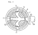
- a plurality of porous ceramics cylindrical filter elements 4 fixed to or gripped by a top header plate 6, a bottom header plate 7 and two intermediate header plates 8, and an inner cylinder partition wall 5 of cylindrical shape.
- the inner cylinder partition wall 5 severes the plurality of filter elements 4 into two tube groups consisting of a group of outside filter elements 4A and a group of inside filter elements 4B. At the same time, the inner cylinder partition wall 5 also divides the cleaned gas chamber on the secondary side of the filter elements 4 constructed outside of the filter elements 4 by the top header plate 6, the bottom header plate 7, the intermediate header plates 8 and the casing 1, into two chambers.
- Two cleaned gas outlet pipes 9A opening in the side wall of the casing 1 are provided at the positions of the same levels as the above-described two intermediate header plates 8, these cleaned gas outlet pipes 9A are connected to a cleaned gas main pipe 19 (Fig. 3) outside of the casing 1, and the cleaned gas chamber formed outside of the inner cylinder partition wall 5 is connected to the cleaned gas main pipe 19 through these cleaned gas outlet pipes 9A.
- cleaned gas outlet pipes 9B opening in the inner cylinder partition wall 5 are provided within the above-described respective cleaned gas outlet pipes 9A in a concentric manner, these cleaned gas outlet pipes 9B are connected to the cleaned gas main pipe 19, and the cleaned gas chamber formed inside of the inner cylinder partition wall 5 is connected to the cleaned gas main pipe 19 through these cleaned gas outlet pipes 9B.
- the cleaned gas outlet pipes 9A and 9B for leading the respective ones of the divided cleaned gas chamber to the cleaned gas main pipe 19 are constructed as concentric double pipes, and until they are connected to the cleaned gas main pipe 19, they are kept independent of each other.
- backwashing devices 15A for the outer pipe group and backwashing devices 15B for the inner pipe group are equipped within the cleaned gas outlet pipes 9A and the cleaned gas outlet pipes 9B, respectively, in these backwashing devices 15A and 15B are respectively provided backwashing control valves 14A and 14B and backwashing nozzles 16A and 16B, and the arrangement is such that backwashing air may be fed from a common high-pressure air source 18 through an air pipe 17.
- reference numeral 10 designates manholes provided in the casing 1 and the dust hopper 3
- numeral 11 designates manholes 5 provided in the inner cylinder partition wall 5
- the filter elements 4 are not arrayed over an appropriate width in the diametrical direction or the like directed from the manholes 11 to the cleaned gas outlet 9B
- walking passages 13 are formed at these portions of the intermediate header plates 8 and the bottom header plate 7.
- a dust-containing gas flowed into the casing 1 through the dust-containing gas inlet 2 enters in the filter elements 4, while it is flowing through the filter element tubes 4 from their inside to their outside, dust is removed, then the filtered cleaned gas is accommodated in the respective cleaned gas chambers divided by the inner cylinder partition wall 5, these cleaned gases would flow through the cleaned gas outlet pipes 9A and 9B, respectively, into the common cleaned gas main pipe 19, and they are fed to an instrument on the downstream side.
- dust seized by the respective filter elements 4 would fall and would be accommodated in the dust hopper 3.
- the cleaned gas chamber is divided into two chambered by the inner cylinder partition wall 5 and the divided cleaned gas chambers can be independently backwashed by means of the backwashing devices 15A and 15B provided just before the joining points of the independent cleaned gas outlet pipes 9A and 9B with the cleaned gas main pipe 19, variations of a pressure and a temperature of a cleaned gas can be greatly reduced by actuating the backwashing devices 15A and 15B after their operating time zones and operating frequencies have been appropriately preset so that dust removal may be carried out in one cleaned gas chamber while backwashing may be performed in the other cleaned gas chamber. Also, by carrying out dust removal in one cleaned gas chamber, even if backwashing is performed in the other cleaned gas chamber, behavior of dust on the side of the dust-containing gas can be made settled.
- a second preferred embodiment of the present invention will be described with reference to Figs. 4 to 6.
- This preferred embodiment is formed by adding the structure described in the following to the construction of the above-described first preferred embodiment, and therefore, in Figs. 4 to 6 component parts identical to those shown in Figs. 1 to 3 are given like reference numerals and further explanation thereof will be omitted in the following description.
- honeycomb type ceramics filter elements 22 are mounted to the lower surface of the bottom header plate 7. As described above, on the bottom header plate 7 are provided walking passages 13 as inspection spaces for the filter element block section within the casing 1, and since the tubular type filter elements are not disposed in these portions, the aforementioned filter elements 22 are mounted to the lower surface of the bottom header plate 7 right under the walking passages 13. In this preferred embodiment, since the cleaned gas chamber is divided into two chambers by the inner cylinder partition wall 5, four honeycomb type filter elements 22 are equipped for the respective cleaned gas chambers as shown in Fig. 5. It is to be noted that these honeycomb type filter elements 22 could be reduced to only two at the diagonally opposed positions, or they could be changed to other numbers.
- the filter element 22 made of a honeycomb type porous ceramics body is mounted to a ceramics body mount member 19 mounted to the bottom header plate 7 penetrating through the header plate.
- This filter element 22 sucks a dust-containing gas from the bottom, the filtered and cleaned gas is accommodated in a cleaned gas chamber 20 formed within the ceramics body mount member 19, and this cleaned gas chamber 20 is communicated with the cleaned gas chamber of the filter block section at the belonging region (location) via a cleaned gas outlet 21 provided in the ceramics body mount member 19.
- a dust containing gas flowed into the casing 1 enters into the tubular type filter elements 4 made of porous ceramics bodies and becomes a cleaned gas while it is flowing through the filter elements 4 from their inside to their outside.
- the dust-containing gas flowing out of the bottom ends of the filter elements 4 has its dust removed by the filter elements 22 made of honeycomb type ceramics bodies and become a cleaned gas, and then it flows through the cleaned gas chambers 20 into the cleaned gas chamber of the filter block section in its belonging region.
- the gas flow rate at the bottom end outlet portion of the tubular filter elements 4 made of porous ceramics bodies in the filter block section is not zero but is equal to the filtering gas flow rate of the above-described honeycomb type filter elements 18.
- Fig. 9 is shown one example of a gas flow velocity distribution in a dust removing apparatus in the prior art, and in the above-described second preferred embodiment of the present invention, the flow velocity at point D in Fig. 9 changes from zero to a finite value such as, for example, about 0.5 m/s, and according to this change, at the respective points on the upstream side of point D also a gas flow velocity would be changed by the same increment.
- a filter element group in a filter block section composed of a plurality of porous ceramics filter elements is grouped into a plurality of groups to divide a cleaned gas chamber into a plurality of cleaned gas chambers and it is made possible to carry out delivery of the cleaned gases in the respective divided cleaned gas chambers independently, and that operating time zones and operating frequencies of backwashing devices for the filter elements in the respective cleaned gas chambers are made different, disturbances applied to instruments in the downstream by variations of a pressure and a temperature of cleaned gases relevant to backwashing which were problems in the prior art, can be minimized, and also there is an advantage that redeposition of dust caused by simultaneous backwashing of all the filter elements can be greatly improved.
- a porous ceramics filter element is mounted to a bottom partition plate partitioning the bottom of the final filter block section, and the cleaned gas filtered by the filter element is fed to the cleaned gas chamber of the filter block section belonging to the mount location, a gas flow velocity at the outlet of the final filter block section can be insured, and accumulation of dust in the filter elements of the respective filter block sections including the final filter block section and blocking of these filter elements can be surely prevented.
- the dust removing apparatus can be simplified, and lowering of an efficiency caused by circulation can be prevented.
Landscapes
- Chemical & Material Sciences (AREA)
- Chemical Kinetics & Catalysis (AREA)
- Physics & Mathematics (AREA)
- Geometry (AREA)
- Filtering Of Dispersed Particles In Gases (AREA)
Priority Applications (4)
| Application Number | Priority Date | Filing Date | Title |
|---|---|---|---|
| US08/307,056 US5518513A (en) | 1994-09-16 | 1994-09-16 | Dust removing apparatus |
| ES94115283T ES2132297T3 (es) | 1994-09-16 | 1994-09-28 | Aparato para quitar el polvo. |
| EP94115283A EP0704234B1 (de) | 1994-09-16 | 1994-09-28 | Apparat zur Entfernung von Staub |
| DE69418603T DE69418603T2 (de) | 1994-09-16 | 1994-09-28 | Apparat zur Entfernung von Staub |
Applications Claiming Priority (2)
| Application Number | Priority Date | Filing Date | Title |
|---|---|---|---|
| US08/307,056 US5518513A (en) | 1994-09-16 | 1994-09-16 | Dust removing apparatus |
| EP94115283A EP0704234B1 (de) | 1994-09-16 | 1994-09-28 | Apparat zur Entfernung von Staub |
Publications (2)
| Publication Number | Publication Date |
|---|---|
| EP0704234A1 true EP0704234A1 (de) | 1996-04-03 |
| EP0704234B1 EP0704234B1 (de) | 1999-05-19 |
Family
ID=26135842
Family Applications (1)
| Application Number | Title | Priority Date | Filing Date |
|---|---|---|---|
| EP94115283A Expired - Lifetime EP0704234B1 (de) | 1994-09-16 | 1994-09-28 | Apparat zur Entfernung von Staub |
Country Status (4)
| Country | Link |
|---|---|
| US (1) | US5518513A (de) |
| EP (1) | EP0704234B1 (de) |
| DE (1) | DE69418603T2 (de) |
| ES (1) | ES2132297T3 (de) |
Families Citing this family (7)
| Publication number | Priority date | Publication date | Assignee | Title |
|---|---|---|---|---|
| DE19527237A1 (de) * | 1995-07-26 | 1997-01-30 | Lurgi Lentjes Babcock Energie | Vorrichtung zum Reinigen von staubbeladenem Gas |
| US6638344B2 (en) | 2001-09-11 | 2003-10-28 | Mcneilus Truck And Manufacturing, Inc. | Plenum pulsed filter vent |
| DE20117862U1 (de) * | 2001-11-06 | 2003-04-10 | DaimlerChrysler AG, 70567 Stuttgart | Dieselpartikelfilter sowie Dieselmotor mit einem Dieselpartikelfilter |
| CN104138695A (zh) * | 2014-08-22 | 2014-11-12 | 苏州卡迪亚铝业有限公司 | 用于气体除尘的过滤式除尘器 |
| CN109248520A (zh) * | 2018-11-27 | 2019-01-22 | 湖南顶立科技有限公司 | 一种过滤装置 |
| CN112521986A (zh) * | 2020-11-10 | 2021-03-19 | 国科永基(北京)工程安装有限公司 | 一种热解粗煤气高温高效防爆型一体模块化除尘设备 |
| CN114210145B (zh) * | 2021-12-17 | 2022-09-13 | 南京工业大学 | 一种高温陶瓷膜除尘器底部的卸灰密封系统 |
Citations (4)
| Publication number | Priority date | Publication date | Assignee | Title |
|---|---|---|---|---|
| FR2426228A1 (fr) * | 1978-05-05 | 1979-12-14 | Procedyne Corp | Systeme et procede de calcination a lit fluidise |
| EP0124863A2 (de) * | 1983-05-06 | 1984-11-14 | Asahi Glass Company Ltd. | Verfahren zum Behandeln von staubhaltigem Gas und Apparat zur Durchführung des Verfahrens |
| WO1991000769A1 (en) * | 1989-07-12 | 1991-01-24 | A. Ahlstrom Corporation | An apparatus and a method for separating particulate material from high-temperature gases |
| JPH0324251B2 (de) * | 1983-09-20 | 1991-04-02 | Asahi Glass Co Ltd |
Family Cites Families (7)
| Publication number | Priority date | Publication date | Assignee | Title |
|---|---|---|---|---|
| US4525184A (en) * | 1983-05-20 | 1985-06-25 | Electric Power Research Institute, Inc. | Vertically tiered particle filtering apparatus |
| DE8914966U1 (de) * | 1989-12-21 | 1990-02-15 | Deutsche Babcock Anlagen Ag, 4200 Oberhausen | Vorrichtung zum Entstauben eines Gasstromes |
| US5143530A (en) * | 1990-10-22 | 1992-09-01 | Westinghouse Electric Corp. | Filtering apparatus |
| DE4226146A1 (de) * | 1992-08-07 | 1994-02-10 | Babcock Energie Umwelt | Vorrichtung zum Filtern von heißen, staubbeladenen Gasen |
| US5284498A (en) * | 1992-11-12 | 1994-02-08 | A. Ahlstrom Corporation | Cylindrical filters in a tube sheet for cleaning high temperature gases |
| US5328492A (en) * | 1993-02-18 | 1994-07-12 | Industrial Filter & Pump Mfg. Co. | Filtration apparatus |
| JP2718615B2 (ja) * | 1993-03-12 | 1998-02-25 | 日本碍子株式会社 | 高温ガス用集塵装置 |
-
1994
- 1994-09-16 US US08/307,056 patent/US5518513A/en not_active Expired - Fee Related
- 1994-09-28 EP EP94115283A patent/EP0704234B1/de not_active Expired - Lifetime
- 1994-09-28 DE DE69418603T patent/DE69418603T2/de not_active Expired - Fee Related
- 1994-09-28 ES ES94115283T patent/ES2132297T3/es not_active Expired - Lifetime
Patent Citations (4)
| Publication number | Priority date | Publication date | Assignee | Title |
|---|---|---|---|---|
| FR2426228A1 (fr) * | 1978-05-05 | 1979-12-14 | Procedyne Corp | Systeme et procede de calcination a lit fluidise |
| EP0124863A2 (de) * | 1983-05-06 | 1984-11-14 | Asahi Glass Company Ltd. | Verfahren zum Behandeln von staubhaltigem Gas und Apparat zur Durchführung des Verfahrens |
| JPH0324251B2 (de) * | 1983-09-20 | 1991-04-02 | Asahi Glass Co Ltd | |
| WO1991000769A1 (en) * | 1989-07-12 | 1991-01-24 | A. Ahlstrom Corporation | An apparatus and a method for separating particulate material from high-temperature gases |
Also Published As
| Publication number | Publication date |
|---|---|
| DE69418603D1 (de) | 1999-06-24 |
| ES2132297T3 (es) | 1999-08-16 |
| EP0704234B1 (de) | 1999-05-19 |
| DE69418603T2 (de) | 1999-10-21 |
| US5518513A (en) | 1996-05-21 |
Similar Documents
| Publication | Publication Date | Title |
|---|---|---|
| EP0483173B1 (de) | Vorrichtung zur Abtrennung von teilchenförmigem Material aus heissen Gasen | |
| US5531798A (en) | Eliminating ash bridging in ceramic filters | |
| EP0881932B1 (de) | Heissgasfilter | |
| KR20080097951A (ko) | 연속 프로세스 유동 여과 시스템에서의 플레넘 기반 고압블로우백 가스 전달 시스템 | |
| EP0475062B1 (de) | Gepulste Reinigungsvorrichtung und Verfahren zum Entfernen von Teilchen aus einem Hochtemperaturgas | |
| JPH04503475A (ja) | 高温ガスから粒状材料を分離する装置 | |
| EP0704234A1 (de) | Apparat zur Entfernung von Staub | |
| US5205850A (en) | Particular filter | |
| US5536285A (en) | Ceramic filtering of gases | |
| EP0083169B1 (de) | Filtrationsapparat mit einem zweiten Gasauslasssystem | |
| US5458665A (en) | Apparatus for filtering gases | |
| US5284498A (en) | Cylindrical filters in a tube sheet for cleaning high temperature gases | |
| EP0689860B1 (de) | Staubsammelapparat | |
| AU670348B2 (en) | Method for cleaning the filter bags of a bag-filter installation | |
| JP3064144B2 (ja) | 除塵装置 | |
| JPH0683768B2 (ja) | 除塵装置 | |
| JP2003251125A (ja) | ガスフィルター装置 | |
| CA2246643C (en) | Hot gas filtering apparatus | |
| JPH06190230A (ja) | 除塵装置 | |
| JPH06190231A (ja) | 除塵装置 | |
| EP0704235A1 (de) | Vorrichtung zur Gegenstromwäsche in einem Apparat zur Entfernung von Staub | |
| JPH06339609A (ja) | 除塵装置 | |
| JPH05212228A (ja) | 高温高圧脱塵装置 |
Legal Events
| Date | Code | Title | Description |
|---|---|---|---|
| PUAI | Public reference made under article 153(3) epc to a published international application that has entered the european phase |
Free format text: ORIGINAL CODE: 0009012 |
|
| 17P | Request for examination filed |
Effective date: 19941026 |
|
| AK | Designated contracting states |
Kind code of ref document: A1 Designated state(s): DE ES GB NL |
|
| 17Q | First examination report despatched |
Effective date: 19960902 |
|
| GRAG | Despatch of communication of intention to grant |
Free format text: ORIGINAL CODE: EPIDOS AGRA |
|
| GRAG | Despatch of communication of intention to grant |
Free format text: ORIGINAL CODE: EPIDOS AGRA |
|
| GRAH | Despatch of communication of intention to grant a patent |
Free format text: ORIGINAL CODE: EPIDOS IGRA |
|
| GRAH | Despatch of communication of intention to grant a patent |
Free format text: ORIGINAL CODE: EPIDOS IGRA |
|
| GRAA | (expected) grant |
Free format text: ORIGINAL CODE: 0009210 |
|
| AK | Designated contracting states |
Kind code of ref document: B1 Designated state(s): DE ES GB NL |
|
| REF | Corresponds to: |
Ref document number: 69418603 Country of ref document: DE Date of ref document: 19990624 |
|
| REG | Reference to a national code |
Ref country code: ES Ref legal event code: FG2A Ref document number: 2132297 Country of ref document: ES Kind code of ref document: T3 |
|
| PLBE | No opposition filed within time limit |
Free format text: ORIGINAL CODE: 0009261 |
|
| STAA | Information on the status of an ep patent application or granted ep patent |
Free format text: STATUS: NO OPPOSITION FILED WITHIN TIME LIMIT |
|
| 26N | No opposition filed | ||
| REG | Reference to a national code |
Ref country code: GB Ref legal event code: IF02 |
|
| PGFP | Annual fee paid to national office [announced via postgrant information from national office to epo] |
Ref country code: NL Payment date: 20050915 Year of fee payment: 12 |
|
| PGFP | Annual fee paid to national office [announced via postgrant information from national office to epo] |
Ref country code: DE Payment date: 20050922 Year of fee payment: 12 |
|
| PGFP | Annual fee paid to national office [announced via postgrant information from national office to epo] |
Ref country code: GB Payment date: 20050928 Year of fee payment: 12 |
|
| PGFP | Annual fee paid to national office [announced via postgrant information from national office to epo] |
Ref country code: ES Payment date: 20051027 Year of fee payment: 12 |
|
| PG25 | Lapsed in a contracting state [announced via postgrant information from national office to epo] |
Ref country code: NL Free format text: LAPSE BECAUSE OF NON-PAYMENT OF DUE FEES Effective date: 20070401 |
|
| PG25 | Lapsed in a contracting state [announced via postgrant information from national office to epo] |
Ref country code: DE Free format text: LAPSE BECAUSE OF NON-PAYMENT OF DUE FEES Effective date: 20070403 |
|
| GBPC | Gb: european patent ceased through non-payment of renewal fee |
Effective date: 20060928 |
|
| NLV4 | Nl: lapsed or anulled due to non-payment of the annual fee |
Effective date: 20070401 |
|
| PG25 | Lapsed in a contracting state [announced via postgrant information from national office to epo] |
Ref country code: GB Free format text: LAPSE BECAUSE OF NON-PAYMENT OF DUE FEES Effective date: 20060928 |
|
| REG | Reference to a national code |
Ref country code: ES Ref legal event code: FD2A Effective date: 20060929 |
|
| PG25 | Lapsed in a contracting state [announced via postgrant information from national office to epo] |
Ref country code: ES Free format text: LAPSE BECAUSE OF NON-PAYMENT OF DUE FEES Effective date: 20060929 |