EP0704251B1 - Ring, Vorrichtung und Verfahren zum Befestigen einer Kappe an einem Behälter - Google Patents
Ring, Vorrichtung und Verfahren zum Befestigen einer Kappe an einem Behälter Download PDFInfo
- Publication number
- EP0704251B1 EP0704251B1 EP95402056A EP95402056A EP0704251B1 EP 0704251 B1 EP0704251 B1 EP 0704251B1 EP 95402056 A EP95402056 A EP 95402056A EP 95402056 A EP95402056 A EP 95402056A EP 0704251 B1 EP0704251 B1 EP 0704251B1
- Authority
- EP
- European Patent Office
- Prior art keywords
- hoop
- fixing
- fixing ring
- ring
- neck
- Prior art date
- Legal status (The legal status is an assumption and is not a legal conclusion. Google has not performed a legal analysis and makes no representation as to the accuracy of the status listed.)
- Expired - Lifetime
Links
Images



Classifications
-
- B—PERFORMING OPERATIONS; TRANSPORTING
- B05—SPRAYING OR ATOMISING IN GENERAL; APPLYING FLUENT MATERIALS TO SURFACES, IN GENERAL
- B05B—SPRAYING APPARATUS; ATOMISING APPARATUS; NOZZLES
- B05B11/00—Single-unit hand-held apparatus in which flow of contents is produced by the muscular force of the operator at the moment of use
- B05B11/01—Single-unit hand-held apparatus in which flow of contents is produced by the muscular force of the operator at the moment of use characterised by the means producing the flow
- B05B11/10—Pump arrangements for transferring the contents from the container to a pump chamber by a sucking effect and forcing the contents out through the dispensing nozzle
- B05B11/1042—Components or details
- B05B11/1043—Sealing or attachment arrangements between pump and container
- B05B11/1049—Attachment arrangements comprising a deformable or resilient ferrule clamped or locked onto the neck of the container by displacing, e.g. sliding, a sleeve surrounding the ferrule
Definitions
- the present invention relates to a device and a method for fixing a dispensing, such as a pump or a valve, on a neck of a container containing product to distribute.
- a fixing ring of the so-called snap type is disposed on the body of a dispensing and is snapped onto the container neck, usually by tabs for this purpose. A hoop is then fitted around said ring to hold it securely on the container neck.
- the snap To obtain a simple and inexpensive assembly operation, the snap must be of the ring and the fitting of the hoop are done mechanically on one and the same mounting unit. Thus, by exerting sufficient force on the hoop, we obtain the snap-fastening of the ring on the neck of the container, and the fitting of the hoop on the ring.
- the object of the present invention is to avoid this drawback by providing a ring fixing ensuring an effective and safe fitting of said hoop.
- An object of the invention is therefore a ring for fixing a distribution member to a neck of a container containing product to be dispensed, said fixing ring being annular and comprising a lower part and an upper part, the lower part comprising fixing means on said neck and the upper part having an opening for the member dispensing device and means for fixedly maintaining said member on said neck, in which said upper part further comprises at least one guide wall element extending vertically in the direction of the longitudinal axis of the dispensing member on the periphery of said fixing ring substantially in extension of said means of fixing of said lower part.
- said fixing means are latching means, advantageously made in the form of lugs.
- said guide wall elements form a crown annular continuous guide.
- a fixing ring produced according to the invention also has the advantage of allow pre-assembly of the hoop on the fixing ring. So the hoop is arranged on said ring around said guide wall elements before being delivered to the customer. It then only has to fill the container with the product of its choice and dispose the assembly formed by the distribution member, the fixing ring and the hoop in the unit mounting.
- the guide wall elements effectively prevent possible separation of the hoop and the fixing ring on delivery, due to transport vibrations, and ensures correct positioning of said hoop for its fitting.
- the guide wall elements therefore have an outside diameter approximately equal to the inside diameter of the hoop, allowing said hoop to be placed by sliding with friction, said friction preventing too easy separation.
- the invention therefore also relates to a device for fixing a member of dispensing on a neck of a container containing product to be dispensed, comprising a annular fixing ring provided with latching means intended to snap onto said neck of the container and an annular hoop whose internal diameter is substantially equal the outside diameter of the fixing ring and which is force fitted onto said fixing ring to prevent the separation of said latching means,
- said fixing ring comprises a lower part and an upper part, the part lower comprising said latching means on said collar and the upper part comprising an opening for the dispensing member and means for holding it fixedly on said neck, said upper part further comprising at least one element of guide wall extending vertically in the direction of the longitudinal axis of the distribution member on the periphery of said fixing ring substantially in extension of said latching means of said lower part.
- this problem is resolved by providing friction between the ring and the hoop higher than the snap resistance of the ring on the neck of the container.
- the outer circumference of the ring is provided snap-fastening, one or more protruding pins on which the hoop rests and by means of which this first snaps the ring onto the container before breaking or deforming said pins under the effect of greater pressure, to come to be fitted around said ring.
- the problem of dimensional tolerances is thus resolved but of such rings can be difficult to mold and thus increase the cost of the device.
- the object of the present invention is to avoid these drawbacks by providing a easy to mold snap ring and hoop, can be assembled on the same mounting unit and ensuring effective mounting regardless of tolerances dimensions, which significantly reduces the manufacturing costs of the dispenser of product.
- the present invention therefore relates to a device for fixing a body of dispensing on a neck of a container containing product to be dispensed, comprising a annular fixing ring provided with latching means intended to snap onto said container neck and an annular hoop having at least one part whose diameter inside is substantially equal to the outside diameter of the fixing ring and which comes force fit onto said fixing ring to prevent said spacing latching means, said fixing ring comprising a lower part and a upper part, the lower part comprising said latching means on said neck and upper part with an opening for the dispensing member and means for holding it fixedly on said neck, said upper part comprising in additionally at least one guide wall member extending vertically in the direction of the longitudinal axis of the dispensing member on the periphery of said ring fixing substantially in extension of said latching means of said part lower, in which said hoop has on the internal face of its lateral wall at less a relief extending vertically over at least part of the height of said side wall, the inside diameter of said
- the hoop can be pre-engaged on the guide wall of the fixing ring for delivery, said at least one relief resting with its lower end on the upper end of the guide wall, so that during mounting, said relief pushes on said ring guide wall, and the ring plus hoop assembly is first snapped onto the neck of the container, before the hoop is fitted onto said Ring.
- said hoop has a plurality of reliefs distributed regularly around the internal face of the side wall of said hoop.
- said relief may consist of an annular shoulder extending horizontally over the entire circumference of the hoop.
- said hoop is made of a material harder than that of the ring of fixation.
- said hoop is metallic and said fixing ring is in plastic material.
- said at least one relief extends vertically from the upper end of said hoop to a point beyond half of the height of said hoop.
- a device for fixing of a dispensing member on a neck of a container containing product to dispensing comprising an annular fixing ring provided with latching means intended to snap onto said container neck and an annular hoop having at least one part whose internal diameter is substantially equal to the external diameter of the ring fixing and which is force fitted onto said fixing ring to prevent the spacing of said latching means, said fixing ring comprising a lower part and an upper part, the lower part comprising said means latching on said collar and the upper part having an opening for the organ dispensing device and means for holding it fixedly on said neck, said part upper further comprising at least one extending guide wall element vertically in the direction of the longitudinal axis of the dispensing member on the periphery of said fixing ring substantially in extension of said means latching of said lower part, in which said hoop has on the face internal side wall of at least one relief extending obliquely over at least part of the height of said side wall, the inside diameter of
- said at least one relief is produced in the form a gadroon or a rib.
- This implementation of the hoop advantageously allows separation by unscrewing the hoop, generally metallic, from the fixing ring, usually plastic. This is particularly of great interest regarding selective recycling of the components of the product distributor.
- annular fixing ring intended to fix a dispensing member on the neck of a container containing product to distribute.
- Two possible variants of such a fixing ring are shown on the Figures 1 and 2.
- the fixing ring 10 has a lower part intended to cooperate with the container neck and an upper part, intended to cooperate with the distribution body.
- the lower part includes fixing means 12, 13 on said collar which can be latching means.
- these means latching are latching tabs 12, preferably distributed around the circumference of the ring 10, and extending in the direction of the central axis of the ring 10, downwards in FIGS. 1 and 2.
- Each of these legs 12 advantageously comprises at its lower end a latching lug 13 projecting from the interior surface of the ring and may deviate slightly under the effect of sufficient force to pass over and then snap under the container neck.
- the lower part of the ring is connected to the upper part at the level of a dish 11 which extends towards the inside of the ring radially with respect to the central axis of the ring, approximately perpendicular to said legs 12.
- Said flat 11 comes to rest either directly on the upper surface of the container neck, or on a seal which may be provided at this location, either on a surface complementary to the distribution to secure it to the container neck.
- the dish 11 may extend radially inside the ring by a turn 15 allowing to fix fixedly part of the distribution organ.
- the dish 11 or the spinner 15 which defines a central opening 16 for the passage of the dispensing member.
- the upper part of the snap ring 10 comprises at in addition to one or more guide wall elements 14 extending vertically in the direction of the central axis of the ring upwards in extension of the latching tabs 12.
- these guide wall elements can form a crown continuous guide ring 14.
- a fixing device a dispensing member on the neck of a container containing product to be dispensed, said device comprising said fixing ring 10 described above as well as a hoop fitting around the legs 12 of said ring 10 to prevent the spacing of said legs 12, and thus securely fix said ring 10, and therefore the member dispenser, on the container neck.
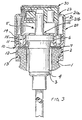
- a product distributor comprising a container 1 provided with a neck 2 and a dispensing member 3 comprising a body 4 extended by a dispensing head 5.
- the container is generally made of glass or plastic material and its neck is cylindrical.
- the distribution unit 3 is generally a pump or a valve according to the nature of the product to be distributed which can be of any consistency.
- the distribution member 3 is held on said neck 2 by means of said dish 11 and said spinner 15 having an opening 16 through which passes said dispensing head 5.
- a seal is provided 7 between the upper surface of the neck 2 of the container and the dish 11 of the fixing ring 10.
- the fixing or snap ring 10 includes one or more several guide wall elements 14 can advantageously be produced under the shape of an annular guide ring 14.
- annular hoop 20 intended to be press fitted onto said ring 10 to prevent the spacing of the snap tabs 12.
- This hoop 20 has at its upper end a opening 23 for the passage of a plug 30 coming to be placed on the head 5 of the member distribution 3.
- the outside diameter of the guide ring 14, or the case where appropriate, guide wall elements is substantially identical to the diameter inside the side wall of the hoop 20.
- the hoop 20 can slide with friction on said guide ring 14 to come into its position of pre-assembly, in which the assembly is then placed in the mounting unit for final assembly.
- the friction between the guide ring 14 and the hoop 20 prevents separation of these two items upon delivery.
- the guide ring 14 extending substantially in extension of the latching tabs 12, a fitting perfectly straight of the hoop 20 around said latching tabs 12 is ensured.
- the hoop 20 has on the internal face 21a of its annular side wall 21 at least one relief 22, 24 extending over part of the height of said side wall 21.
- the diameter inside of the hoop 20 at the level of said at least one relief 22, 24 is slightly lower the outside diameter of the ring 10.
- said at at least one relief 22, 24 can be implemented in the form of ribs or gadroons.
- the outer surface 21b of the hoop 20 remains perfectly cylindrical, which can be an aesthetic advantage.
- the reliefs 22 extend vertically on the side wall 21.
- the hoop 20 comprises a plurality of these reliefs 22 distributed regularly around the internal face 21a of said side wall 21, as visible in FIGS. 5 and 6.
- these reliefs 22 extend from the end upper of said hoop 20 to at least half the height of said hoop 20 and are all identical.
- said relief 22 consists of an annular shoulder extending horizontally over the entire circumference of the hoop 20.
- the reliefs 24 extend obliquely on the side wall 21.
- said at least one oblique relief 24 has an elongated shape to form an internal thread on the annular side wall 21 of the hoop 20.
- This implementation is particularly interesting when the ring 10 is made of plastic and the hoop 20 is made of metal. Indeed, the plastic material of the ring marries by creep, after a lapse of time which depends on the hardness of said plastic, the shape of said at least one relief 24 of the hoop 20.
- the internal face of the wall lateral 21 of the hoop 20 has a single relief 24.
- this oblique relief extends approximately one full revolution of the circumference of the side wall 21. It is well clear in this case that the slope of said relief 24 is relatively small.
- the internal face of the wall annular lateral side of the hoop is provided with several oblique reliefs 24 parallel which are advantageously distributed regularly around the circumference of said wall lateral.
- the fixing ring 10 is threaded around the head 5 of the dispensing member 3 and is fixed by its turn 15 on the upper part 6 of the body of the distribution 3.
- the hoop 20 is then placed around the wall element (s) of guide 14 advantageously forming an annular ring of said fixing ring 10 and abuts, via the lower ends 22a of the reliefs 22, on the upper end of the annular ring 14 of the fixing ring 10.
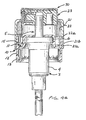
- the assembly consisting of the distribution member 3, the ring 10 and the hoop 20 is thus in its pre-engaged position shown in Figure 4a, in which it will be delivered to the customer. This one then just fill the container with the product of your choice and place the said container 1 and said assembly 3, 10, 20 in a single mounting unit.
- the body 4 of the dispensing member 3 is thus introduced into the neck of the container and the latching tabs 12 come to rest on the seal 7 disposed on the upper surface of the neck 2 of the container 1.
- the assembly is then placed in the assembly where a first vertical pushing force F1 is applied to the hoop 20.
- the inner diameter of this hoop 20 at the reliefs 22 being less than the diameter outside of the fixing ring 10, said hoop can no longer slide on said Ring.
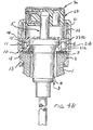
- the force F1 is therefore transmitted by the hoop 20 to the fixing ring 10, the snap tabs 12 move apart under the effect of said force F1, which makes it slide said ring on the container neck until the latching tabs 12 come snap under said collar 2, as visible in FIG. 4b.
- the body 4 of the organ of distribution 3 is then fixedly placed inside the container, the seal being provided by the annular seal 7.
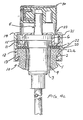
- a second vertical thrust force F2 is then applied to the hoop 20.
- This second force F2 is greater than the first force F1 and is sufficient to fit at forces said hoop 20 on the fixing ring 10 via the reliefs 22.
- the latching tabs 12 of the fixing ring 10 are then held in their locking position and can no longer move apart, which ensures the fixing final distribution member 3 in the container, as shown in Figure 4c.
- the difference required between the forces F1 and F2 depends on the radial thickness of the reliefs 22 of the hoop 20. A sufficient radial thickness ensures assembly effective, even if the latching tabs 12 are, for manufacturing reasons, a slightly less flexible than expected, which increases the snap resistance.
- the hoop 20 being advantageously metallic, the press fitting thereof on the fixing ring 10, generally made of plastic, is possible despite the diameter lower interior of said hoop 20, at the level of the reliefs 22, relative to the diameter outside of said ring 10, said reliefs 22 being embedded in the crown of annular guide 14 of the fixing ring 10.
Landscapes
- Closures For Containers (AREA)
- Containers And Packaging Bodies Having A Special Means To Remove Contents (AREA)
- Nozzles (AREA)
Claims (16)
- Befestigungsvorrichtung zum Befestigen eines Abgabeorgans (3) auf einem Hals (1) eines Behälters, der das abzugebende Produkt enthält, mit einem Befestigungsring (10) für das Abgabeorgan (3) auf dem Hals (1), wobei der Befestigungsring kreisringförmig ist und einen unteren Teil und einen oberen Teil umfaßt, wobei der untere Teil Befestigungsmittel (12, 13) auf dem Hals und der obere Teil eine Öffnung (16) für das Abgabeorgan umfaßt, sowie mit Mitteln (11, 15) zum Festhalten des Organs auf dem Hals, wobei die Vorrichtung weiterhin einen kreisringförmigen Mantelring (20) umfaßt, dessen Innendurchmesser im wesentlichen gleich im Außendurchmesser des Befestigungsringes (10) ist und der auf den Befestigungsring aufgepresst werden kann, um ein Wegbewegen der Befestigungsmittel (12, 13) zu verhindern, dadurch gekennzeichnet, daß der obere Teil des Befestigungsringes weiterhin wenigstens ein Führungswandelement (14) umfaßt, das sich vertikal in Richtung der Längsachse des Abgabeorgans über den Umfang des Befestigungsringes (10) im wesentlichen in Verlängerung der Befestigungsmittel des unteren Teils erstreckt, wobei das wenigstens eine Führungswandelement geeignet ist, den Mantelring (20) vor seinem Aufpressen aufzunehmen und zu halten.
- Befestigungsvorrichtung nach Anspruch 1, bei der die Befestigungsmittel des Rings Rastklauen sind.
- Befestigungsvorrichtung nach Anspruch 1 oder 2, bei der die Führungswandelemente einen ringförmigen Kranz (14) für eine kontinuierliche Führung bilden.
- Befestigungsvorrichtung nach einem der Ansprüche 1 bis 3, bei der der Mantelring (20) auf der Innenfläche seiner Seitenwand (21) wenigstens ein Relief (22) umfaßt, das sich zumindest über einen Teil der Höhe dieser Seitenwand vertikal erstreckt, wobei der Innendurchmesser des Mantelrings (20) im Bereich des wenigstens einen Reliefs (22) geringfügig kleiner als der Außendurchmesser des Befestigungsrings (10) ist.
- Befestigungsvorrichtung nach Anspruch 4, bei der das wenigstens eine Relief (22) sich ausgehend vom oberen Ende (23) des Mantelrings (20) bis zu einem Punkt erstreckt, der sich jenseits der Mitte der Höhe des Mantelrings befindet.
- Befestigungsvorrichtung nach Anspruch 4 oder 5, bei der der Mantelring (20) eine Vielzahl von Reliefs (22) umfaßt, die regelmäßig um die Innenfläche der Seitenwand (21) des Mantelrings herum verteilt angeordnet sind.
- Befestigungsvorrichtung nach Anspruch 4, bei der das Relief von einer ringförmigen Schulter (22) gebildet wird, die sich horizontal über den gesamten Umfang des Mantelrings (20) erstreckt.
- Befestigungsvorrichtung nach einem der Ansprüche 1 bis 3, bei welcher der Mantelring (20) auf der Innenfläche seiner Seitenwand (21) wenigstens ein Relief (24) umfaßt, das sich in schräger Weise zumindest über einen Teil der Höhe der Seitenwand erstreckt, wobei der Innendurchmesser des Mantelrings (20) im Bereich des wenigstens einen Reliefs (24) geringfügig kleiner als der Außendurchmesser des Befestigungsringes (10) ist.
- Befestigungsvorrichtung nach Anspruch 8, bei der die Innenfläche der ringförmigen Seitenwand (21) des Mantelrings (20) mit einem einzigen schrägen Relief (24) versehen ist, das sich ungefähr über die Gesamtheit des Umfangs der ringförmigen Wand (21) erstreckt.
- Befestigungsvorrichtung nach Anspruch 8, bei der die Innenfläche der ringförmigen Seitenwand (21) des Mantelrings (20) mit mehreren schräg verlaufenden, parallelen Reliefs (24) versehen ist, die um seinem Umfang herum verteil angeordnet sind.
- Befestigungsvorrichtung nach einem der Ansprüche 4 bis 10, bei der das wenigstens eine Relief (22, 24) die Form einer Hohlprägung aufweist.
- Befestigungsvorrichtung nach einem der Ansprüche 4 bis 10, bei der das wenigstens eine Relief (22, 24) eine Rippe ist.
- Befestigungsvorrichtung nach einem der vorhergehenden Ansprüche bei der der Mantelring (20) aus einem härterem Material hergestellt ist, als der Befestigungsring (10).
- Befestigungsvorrichtung nach Anspruch 13, bei der der Mantelring (20) aus Metall und der Befestigungsring (10) aus Kunststoff besteht.
- Befestigungsverfahren für ein Abgabeorgan (3) auf dem Hals (1) eines Behälters, der das abzugebende Produkt enthält, wobei das Verfahren folgende Schritte umfaßt:dadurch gekennzeichnet, daß das Verfahren die folgenden Schritte umfaßt:Anordnen eines kreisringförmigen Befestigungsringes (10) auf dem Abgabeorgan, wobei der Ring auf der einen Seite mit Rastmitteln (12, 13) und auf der gegenüberliegenden Seite mit einer Führungswand (14) versehen ist, die sich in Verlängerung der Rastmittel in Richtung der Längsachse des Befestigungsringes erstreckt- vorläufiges Ineingriffbringen eines kreisringförmigen Mantelrings (20) auf der Führungswand (14) des Befestigungsringes (10,) wobei der Mantelring einen Innendurchmesser aufweist, der im wesentlichen gleich dem Außendurchmesser des Befestigungsringes ist,- Positionieren der Baueinheit, die das Abgabeorgan (3), dem Befestigungsring (10) und den Mantelring (20) umfaßt, auf dem Hals (1) des BehältersAusüben einer ersten Kraft F1 auf den Mantelring (20) der an der Führungswand (14) des Befestigungsringes (10) anliegt und diesen Befestigungsring (10) auf den Hals des Behälters schiebt, wobei sich die Rastmittel (12, 13) unter der Wirkung der Kraft F1 spreizen, bevor sie auf dem Hals des Behälters einrasten, undAusüben einer zweiten Kraft F2, die größer als die erste Kraft F1 ist, auf den Mantelring (20), wobei die zweite Kraft F2 ausreichend ist, um den Mantelring (20) auf den Befestigungsring (10) aufzupressen, wodurch der Mantelring (20) ein Spreizen der Rastmittel (12, 13) des Befestigungsringes (10) verhindert.
- Befestigungsverfahren nach Anspruch 15, bei dem der kreisringförmige Mantelring (20) auf der Innenfläche seiner Seitenwand (21) mit wenigstens einem Relief (22, 24) versehen ist, das sich zumindest über einen Teil der Höhe der Seitenwand erstreckt, wobei der Innendurchmesser des Mantelrings (20) im Bereich des wenigstens einen Reliefs (22, 24) geringfügig kleiner ist als der Außendurchmesser des Befestigungsringes (10), wobei der Mantelring (20) auf der Führungswand (14) vorläufig zum Eingriff gebracht ist, bis das untere Ende (22a, 24a) des wenigstens einen Reliefs (22, 24) des Mantelrings (20) am oberen Ende der Führungswand (14) des Befestigungsringes (10) derart zur Anlage kommt, daß beim Schritt des Ausübens einer ersten Kraft F1 auf den Mantelring (20) dieser an der Führungswand (14) des Befestigungsringes (10) mittels des unteren Endes (22a, 24a) des wenigstens einen Reliefs (22, 24) zur Anlage kommt und den Befestigungsring (10) auf den Hals des Behälters schiebt, wobei sich die Rastmittel (12, 13) unter der Wirkung der Kraft F1 spreizen, bevor sie am Hals des Behälters einrasten.
Applications Claiming Priority (2)
| Application Number | Priority Date | Filing Date | Title |
|---|---|---|---|
| US08/311,041 US5562219A (en) | 1994-09-22 | 1994-09-22 | Device for attaching a dispenser member to a receptacle |
| US311041 | 1994-09-22 |
Publications (4)
| Publication Number | Publication Date |
|---|---|
| EP0704251A2 EP0704251A2 (de) | 1996-04-03 |
| EP0704251A3 EP0704251A3 (de) | 1996-09-25 |
| EP0704251B1 true EP0704251B1 (de) | 2002-04-10 |
| EP0704251B3 EP0704251B3 (de) | 2015-05-20 |
Family
ID=23205134
Family Applications (1)
| Application Number | Title | Priority Date | Filing Date |
|---|---|---|---|
| EP19950402056 Expired - Lifetime EP0704251B3 (de) | 1994-09-22 | 1995-09-12 | Vorrichtung und Verfahren zum Befestigen einer Kappe an einem Behälter |
Country Status (5)
| Country | Link |
|---|---|
| US (6) | US5562219A (de) |
| EP (1) | EP0704251B3 (de) |
| JP (1) | JP3536266B2 (de) |
| DE (1) | DE69526296T2 (de) |
| ES (1) | ES2174908T7 (de) |
Families Citing this family (102)
| Publication number | Priority date | Publication date | Assignee | Title |
|---|---|---|---|---|
| US5620113A (en) * | 1992-05-22 | 1997-04-15 | Meshberg; Philip | Dispenser and method of its use |
| US5562219A (en) * | 1994-09-22 | 1996-10-08 | Valois, S.A. | Device for attaching a dispenser member to a receptacle |
| FR2737471B1 (fr) * | 1995-08-01 | 1997-09-05 | Valois | Bague de fixation a double indexation |
| CA2211629A1 (en) * | 1996-09-17 | 1998-03-17 | Bernard Sams | Vial connector assembly for a medicament container |
| GB9626960D0 (en) * | 1996-12-27 | 1997-02-12 | Glaxo Group Ltd | Valve for aerosol container |
| FR2760725B1 (fr) * | 1997-03-14 | 1999-05-28 | Teleplastics Ind | Dispositif distributeur pour produits fluides |
| US5950880A (en) * | 1997-04-14 | 1999-09-14 | Valois S.A. | Set of components for assembly as a dispensing package of the non-vented type having a take-up piston |
| US5975369A (en) | 1997-06-05 | 1999-11-02 | Erie County Plastics Corporation | Resealable pushable container closure and cover therefor |
| FR2764584B1 (fr) | 1997-06-13 | 1999-08-20 | Valois Sa | Distributeur de produit fluide a bague de fixation encliquetable |
| US6244469B1 (en) | 1998-01-14 | 2001-06-12 | Michael G. Knickerbocker | Child resistant trigger for dispenser |
| US7963955B2 (en) * | 1998-02-27 | 2011-06-21 | Boehringer Ingelheim International Gmbh | Container for a medicinal liquid |
| HU224872B1 (en) * | 1998-03-03 | 2006-03-28 | Mihaly Rigo | Closure assembly for dispensing bottled beverages |
| FR2776989B1 (fr) | 1998-04-06 | 2000-06-09 | Valois Sa | Organe de fixation de dispositif de distribution a habillage ogival |
| FR2777209B1 (fr) * | 1998-04-14 | 2000-06-30 | Sofab | Dispositif pour le prepositionnement d'une collerette d'habillage sur un bouton-poussoir |
| US6155452A (en) * | 1998-12-28 | 2000-12-05 | Laurent; Hervej. | Arrangement for resealing carbonated beverage containers |
| US6253941B1 (en) | 1999-01-19 | 2001-07-03 | Crown Cork & Seal Technologies Corporation | Assembly for securing and sealing a dispenser to a flanged container |
| DE60044526D1 (de) * | 1999-01-19 | 2010-07-22 | Rexam Beauty & Closures Inc | Vorrichtung zum fixieren eines flüssigkeitsspenders |
| DE19940713A1 (de) * | 1999-02-23 | 2001-03-01 | Boehringer Ingelheim Int | Kartusche für eine Flüssigkeit |
| BR0009237B1 (pt) * | 1999-03-23 | 2011-01-25 | dispositivo para o fechamento de garrafas. | |
| US6216925B1 (en) * | 1999-06-04 | 2001-04-17 | Multi-Vet Ltd. | Automatic aerosol dispenser |
| FR2800718B1 (fr) | 1999-11-09 | 2002-01-18 | Valois Sa | Distributeur de produit fluide a coque rigide et poche souple |
| US6398133B1 (en) | 1999-12-22 | 2002-06-04 | Emsar, Inc. | Dispensing head for a squeeze dispenser |
| FR2808513B1 (fr) * | 2000-05-05 | 2002-07-26 | Valois Sa | Organe de fixation pour fixer une pompe ou une valve sur un col de recipient |
| US6799690B2 (en) * | 2000-05-05 | 2004-10-05 | Valois S.A. | Attachment device to attach a pump or valve onto a recipient neck |
| FR2809711B1 (fr) * | 2000-05-31 | 2002-08-23 | Valois Sa | Distributeur a organe de fixation et organe de fixation pour un tel distributeur |
| FR2809714B1 (fr) * | 2000-05-31 | 2002-12-06 | Valois Sa | Distributeur a organe de fixation a etancheite peripherique |
| US6595395B2 (en) | 2000-05-31 | 2003-07-22 | Valois S.A. | Dispenser having a fixing member, and a fixing member for such a dispenser |
| EP1309409B1 (de) * | 2000-05-31 | 2010-12-01 | Valois Sas | Befestigungselement für eine abgabevorrichtung |
| US6341706B1 (en) | 2000-06-01 | 2002-01-29 | Color Access, Inc. | Snap-on plastic neck for glass containers |
| FR2815610B1 (fr) * | 2000-10-23 | 2003-02-14 | Valois Sa | Dispositif de fixation et distributeur utilisant un tel dispositif de fixation |
| FR2818249B1 (fr) * | 2000-12-20 | 2003-03-28 | Valois Sa | Dispositif de fixation d'organe de distribution sur un col de recipient |
| FR2820123B1 (fr) * | 2001-01-30 | 2003-05-02 | Valois Sa | Dispositif de fixation d'organe de distribution sur un col de recipient |
| FR2845357B1 (fr) * | 2002-10-07 | 2005-09-16 | Valois Sas | Dispositif de fixation et distributeur comprenant un tel dispositif de fixation |
| FR2846304B1 (fr) * | 2002-10-28 | 2006-03-03 | Valois Sas | Element de fixation d'un organe de distribution de produit fluide et dispositif de distribution de produit fluide comportant un tel element de fixation |
| US6776311B2 (en) * | 2002-11-13 | 2004-08-17 | Emsar, Incorporated | Dispenser assembly for a fragrance or personal care bottle and a method of assembling same |
| FR2848194B1 (fr) * | 2002-12-05 | 2005-06-24 | Valois Sas | Organe de fixation pour fixer une pompe ou une valve sur un reservoir |
| US7011236B2 (en) * | 2003-04-03 | 2006-03-14 | Rexam Beauty And Closure Inc. | Assembly for securing and sealing a dispenser including a decorative collar to a flanged container |
| FR2859983B1 (fr) * | 2003-09-22 | 2006-03-10 | Valois Sas | Dispositif de fixation et procede de montage pour fixer un organe de distribution sur une ouverture de reservoir |
| US6840461B1 (en) * | 2003-10-03 | 2005-01-11 | Whitmire Micro-Gen Research Laboratories, Inc. | Adapter clamp for aerosol can |
| FR2865199B1 (fr) * | 2004-01-16 | 2007-04-27 | Valois Sas | Dispositif de distribution de produit fluide et procede d'assemblage d'un tel dispositif |
| FR2867254B1 (fr) * | 2004-03-04 | 2007-12-07 | Valois Sa | Bague de fixation et dispositif de distribution de produit fluide comportant une telle bague. |
| US20060071032A1 (en) * | 2004-09-03 | 2006-04-06 | Ciavarella Nick E | Stroke and output limiter for positive displacement pump bottle |
| US20060249953A1 (en) * | 2005-05-04 | 2006-11-09 | B&G Equipment Company, A Delaware Corporation | Quick connector for rimmed vessel |
| FR2886632B1 (fr) * | 2005-06-03 | 2007-09-07 | Valois Sas | Ensemble de fixation d'un organe de distribution de produit fluide |
| US20060273061A1 (en) * | 2005-06-06 | 2006-12-07 | Mark Fricke | Method and device for a child resistant dropper closure |
| DE502006008270D1 (de) * | 2005-09-19 | 2010-12-23 | Valois Sas | Verriegelungshülse zur Befestigung einer Verschlusseinrichtung sowie Verschlusseinrichtung |
| FR2891529B1 (fr) * | 2005-10-04 | 2007-12-07 | Valois Sas | Organe de recouvrement, procede de fabrication d'un tel organe et distributeur comprenant un tel organe. |
| FR2891530B1 (fr) * | 2005-10-04 | 2007-12-07 | Valois Sas | Organe de recouvrement, procede de fabrication d'un tel organe et distributeur de produit fluide utlisant un tel organe. |
| FR2891533B1 (fr) * | 2005-10-04 | 2007-12-07 | Valois Sas | Organe de recouvrement, procede de fabrication d'un tel organe et distributeur de produit fluide utilisant un tel organe. |
| FR2897851B1 (fr) * | 2006-02-24 | 2008-04-25 | Valois Sas | Dispositif de distribution et distributeur comprenant un tel dispositif |
| GB0610541D0 (en) * | 2006-05-26 | 2006-07-05 | Bespak Plc | Improvements in or relating to dispensing apparatus |
| GB2448838B (en) | 2006-05-26 | 2009-02-11 | Consort Medical Plc | Improvements in or relating to dispensing apparatus |
| FR2902675B1 (fr) * | 2006-06-21 | 2008-09-12 | Lvmh Rech | Buse de distribution de produit de fluide et dispositif de distribution de produit de fluide comprenant une telle buse |
| FR2904812B1 (fr) * | 2006-08-09 | 2008-10-24 | Rexam Dispensing Systems Sas | Dispositif de fixation, ensemble de distribution comprenant un tel dispositif, distribeur comprenant un tel ensemble et procede de montage d'un tel distributeur |
| US7757902B2 (en) * | 2006-09-06 | 2010-07-20 | Emsar, Inc. | Dispenser assembly for a fluid dispensing receptacle and method of assembling same |
| FR2908117B1 (fr) * | 2006-11-07 | 2009-01-16 | Valois Sas | Dispositif de fixation et distributeur utilisant un tel dispositif |
| US20080128481A1 (en) * | 2006-12-05 | 2008-06-05 | Robertson Ronald D | Stackable storage container with insulating sleeve |
| WO2008098939A1 (en) * | 2007-02-12 | 2008-08-21 | Inbev S.A. | Container, chime and assembly of both |
| US8286838B2 (en) * | 2007-03-30 | 2012-10-16 | LF Beauty | Leak proof fragrance bottle |
| GB0707573D0 (en) * | 2007-04-19 | 2007-05-30 | 3M Innovative Properties Co | Dispensing device with locking member |
| FR2916743B1 (fr) * | 2007-05-29 | 2009-08-28 | Valois Sas | Dispositif de fixation pour fixer une pompe sur un reservoir et distributeur utilisant un tel dispositif de fixation |
| US8985405B2 (en) * | 2007-06-28 | 2015-03-24 | Meadwestvaco Calmar, Inc. | Bottle and valve fitment for containers |
| US20090014679A1 (en) * | 2007-07-13 | 2009-01-15 | Precision Valve Corporation | Plastic aerosol valve and method of assembly, mounting and retention |
| MX345749B (es) * | 2007-08-28 | 2017-02-14 | Westrock Dispensing Systems Inc | Válvulas de plástico y métodos para utilizarlas. |
| FR2925034B1 (fr) * | 2007-12-12 | 2009-12-18 | Valois Sas | Dispositif de fixation et distributeur utilisant un tel dispositif. |
| FR2925033B1 (fr) * | 2007-12-12 | 2012-10-05 | Valois Sas | Distributeur de produit fluide. |
| FR2927886B1 (fr) * | 2008-02-26 | 2013-02-22 | Segede | Recipient a indexation |
| USD636668S1 (en) | 2008-03-24 | 2011-04-26 | Mary Kay Inc. | Dip tubes |
| US8376192B2 (en) | 2008-03-24 | 2013-02-19 | Mary Kay Inc. | Apparatus for dispensing fluids using a press-fit diptube |
| EP2279044A1 (de) * | 2008-05-19 | 2011-02-02 | MeadWestvaco Corporation | Pumpenhaltering und verfahren zu seiner verwendung |
| US9789502B2 (en) | 2008-06-05 | 2017-10-17 | Mary Kay Inc. | Apparatus for dispensing fluids using a removable bottle |
| FR2932783B1 (fr) * | 2008-06-18 | 2010-09-03 | Rexam Dispensing Sys | Flacon de distribution d'un produit fluide comprenant un manchon deformable et devissable |
| EP2135682B2 (de) | 2008-06-18 | 2016-08-17 | Albéa le Tréport | Spender für ein flüssiges Produkt, der ein deformierbares und abschraubbares Befestigungselement zur Besfestigung der Spenderpumpe umfasst |
| US8201710B2 (en) * | 2008-10-15 | 2012-06-19 | S.C. Johnson & Son, Inc. | Attachment mechanism for a dispenser |
| FR2939776B1 (fr) * | 2008-12-12 | 2013-07-05 | Valois Sas | Bague de fixation et distributeur comprenant une telle bague. |
| FR2945283B1 (fr) * | 2009-05-06 | 2015-06-26 | Valois Sas | Dispositif de fixation pour fixer une pompe sur un col de reservoir |
| FR2948344B1 (fr) | 2009-07-27 | 2011-09-02 | Valois Sas | Systeme de fixation demontable. |
| FR2948641B1 (fr) * | 2009-07-28 | 2016-02-12 | Rexam Dispensing Sys | Systeme de fixation d'une pompe de distribution sur le col d'un flacon contenant un produit fluide |
| FR2950035B1 (fr) | 2009-09-15 | 2011-09-02 | Raymond A & Cie | Coiffe de verrouillage pour recipient a col |
| FR2950865B1 (fr) * | 2009-10-01 | 2011-10-28 | Raymond A & Cie | Coiffe de verrouillage pour recipient a col avec une capsule a pattes de fixation |
| FR2952620B1 (fr) * | 2009-11-19 | 2011-12-30 | Valois Sas | Distributeur de produit fluide. |
| WO2011116201A2 (en) * | 2010-03-18 | 2011-09-22 | Meadwestvaco Calmar, Inc. | Pump and bottle fitments and methods for using the same |
| FR2957903B1 (fr) * | 2010-03-25 | 2014-01-24 | Valois Sas | Distributeur de produit fluide. |
| FR2957900B1 (fr) * | 2010-03-25 | 2012-05-11 | Rexam Dispensing Sys | Systeme de fixation d'un organe de distribution d'un produit fluide sur le col d'un flacon |
| FR2963610B1 (fr) * | 2010-08-03 | 2012-08-31 | Valois Sas | Systeme de fixation et distributeur de produit fluide utilisant un tel systeme. |
| FR2975674B1 (fr) * | 2011-05-23 | 2013-06-28 | Valois Sas | Bague de fixation et distributeur de produit fluide utilisant une telle bague. |
| FR2986782B1 (fr) | 2012-02-13 | 2014-03-07 | Raymond A & Cie | Dispositif de verrouillage de bouchon sur recipient a collerette, recipient a collerette obture par bouchon pourvu d'un tel dispositif de verrouillage |
| US9016524B2 (en) * | 2012-09-17 | 2015-04-28 | Owens-Brockway Glass Container Inc. | Tamper-evident anti-refill dispensing fitment for a container |
| US10427845B2 (en) * | 2012-11-30 | 2019-10-01 | Obrist Closures Switzerland Gmbh | Tamper evident closure |
| FR3000039B1 (fr) * | 2012-12-21 | 2015-07-03 | Dior Christian Parfums | Systeme de recouvrement escamotable et ensemble de conditionnement et d'application de produit equipe d'un tel systeme |
| FR3001954B1 (fr) | 2013-02-14 | 2015-02-27 | Transformation Des Elastomeres A Usages Medicaux Et Ind Soc D | Dispositif de fixation pour obturer un reservoir de produit fluide. |
| JP5973365B2 (ja) * | 2013-03-01 | 2016-08-23 | 株式会社ジーシー | 歯科用ミキサー |
| FR3008864B1 (fr) * | 2013-07-26 | 2016-09-02 | Albea Services | Dispositif pour dissimuler au moins une partie d'une pompe d'un flacon pour produit cosmetique, flacon comprenant un tel dispositif et procede de fabrication d'un tel dispositif |
| EP3220852B1 (de) | 2014-11-20 | 2026-03-25 | Boehringer Ingelheim Vetmedica GmbH | Behälter für einen inhalator |
| US10710105B2 (en) * | 2017-10-31 | 2020-07-14 | Zhejiang Rongpeng Air Tools Co., Ltd. | Disposable cleaning-free paint pot |
| US10486892B1 (en) * | 2018-08-22 | 2019-11-26 | The Procter & Gamble Company | Packages and arrays of packages for plastic aerosol dispensers |
| FR3094894B1 (fr) * | 2019-04-11 | 2021-04-09 | Aptar France Sas | Distributeur de produit fluide |
| FR3095133B1 (fr) * | 2019-04-17 | 2021-09-24 | Shiseido Int France | Distributeur de produit fluide |
| JP7218063B2 (ja) * | 2019-06-28 | 2023-02-06 | 株式会社吉野工業所 | 吐出容器 |
| WO2021202818A1 (en) * | 2020-03-31 | 2021-10-07 | Partsch George J | Universal capping system and the method of use thereof |
| FR3111337B1 (fr) * | 2020-06-12 | 2022-06-03 | Aptar France Sas | Organe de fixation de pompe |
| BE1032514B1 (nl) * | 2024-11-07 | 2025-10-30 | Altachem Nv | Koppelstuk |
Family Cites Families (101)
| Publication number | Priority date | Publication date | Assignee | Title |
|---|---|---|---|---|
| BE545477A (de) * | ||||
| US34976A (en) * | 1862-04-15 | Improved cover for fruit-jars | ||
| US681774A (en) * | 1896-03-09 | 1901-09-03 | Leonard C Bailey | Bottle. |
| US886994A (en) * | 1905-04-15 | 1908-05-05 | Cie Des Bouchages Hermetiques Simplex | Closure for receptacles. |
| US835366A (en) * | 1905-12-07 | 1906-11-06 | William F Purcell | Bottle-stopper. |
| US1609453A (en) * | 1924-07-02 | 1926-12-07 | George D Atwood | Bottle closure |
| GB239215A (en) * | 1924-08-26 | 1926-04-22 | Francis Albert Joseph Poncet | Improvements in or relating to siphons for gaseous liquids |
| US1758696A (en) * | 1928-05-25 | 1930-05-13 | Ralph A Graham | Bottle closure |
| AT114665B (de) * | 1928-09-06 | 1929-10-25 | Lingner Werke Ag | Flüssigkeitszerstäuber. |
| US1985258A (en) * | 1929-09-20 | 1934-12-25 | Willy Faltlhauser | Bottle closure |
| US2045480A (en) * | 1933-07-31 | 1936-06-23 | Magnesen Seal And Closure Comp | Closure for bottles, jars, and similar containers |
| US1982497A (en) * | 1933-09-13 | 1934-11-27 | Textile Patent & Process Compa | Pump |
| US2132775A (en) * | 1935-08-30 | 1938-10-11 | Casablancas Fernando | Closure for sealing bottles and like receptacles |
| US2125790A (en) * | 1935-09-11 | 1938-08-02 | Charles W Johnson | Nonrefillable bottle and like containers |
| US2117407A (en) | 1937-01-09 | 1938-05-17 | Wheeling Stamping Co | Tube and cap assembly |
| US2339343A (en) * | 1940-04-11 | 1944-01-18 | Magnesen Seal And Closure Comp | Closure for bottles, jars, and other containers |
| US2347605A (en) * | 1940-04-18 | 1944-04-25 | Charles D Magnesen | Closure for bottles, jars, and similar containers |
| US2398554A (en) * | 1942-07-31 | 1946-04-16 | F N Burt Company Inc | Closure |
| US2372725A (en) * | 1942-11-09 | 1945-04-03 | Otto A Koehler | Plastic bottle cap |
| US2421356A (en) * | 1943-01-28 | 1947-05-27 | Sav Way Ind Inc | Bottle cap |
| US2439845A (en) * | 1943-10-12 | 1948-04-20 | Bland Jamison C | Bottle cap |
| US2483055A (en) * | 1944-08-21 | 1949-09-27 | Krasberg Rudolf | Bottle cap |
| US2444779A (en) * | 1946-04-06 | 1948-07-06 | Krasberg Rudolf | Bottle cap |
| US2576580A (en) * | 1948-11-16 | 1951-11-27 | Mero Co Inc | Bottle cap |
| AT189528B (de) | 1952-08-13 | 1957-04-10 | Hellmut Golde | Verschlußkappe für Flaschen u. dgl. Behälter |
| US2723773A (en) * | 1952-10-24 | 1955-11-15 | Interseal Corp | Bottle closures |
| GB722642A (en) * | 1952-10-24 | 1955-01-26 | Inter Seal Corp | Improvements in bottle closures |
| US2814405A (en) * | 1954-12-31 | 1957-11-26 | Illinois Tool Works | Closure device |
| GB800043A (en) * | 1955-02-23 | 1958-08-20 | Alfred Bayetto | Closing arrangements for bottles, tubes, jars, and the like containers provided witha peripheral bead |
| DE1164864B (de) | 1958-06-20 | 1964-03-05 | Metallwerke Adolf Hopf K G | Flaschenverschluss |
| US3055560A (en) * | 1959-05-18 | 1962-09-25 | Meshberg Philip | Metering valve assembly |
| FR1262580A (fr) * | 1959-10-15 | 1961-06-05 | Récipient démontable pour aérosol | |
| US3191815A (en) * | 1961-05-08 | 1965-06-29 | Graham Cecil Robert Montgomery | Tops for aerosol containers |
| US3120906A (en) * | 1961-06-12 | 1964-02-11 | Drackett Co | Dispensing pump with container attaching means |
| US3159318A (en) * | 1962-03-20 | 1964-12-01 | Edward H Green | Aerosol valve housing construction and method of making same |
| US3138304A (en) * | 1962-06-12 | 1964-06-23 | Uniplast Dr Raehs Kg Fa | Valve assembly for aerosol containers |
| DK99245C (da) * | 1962-10-31 | 1964-07-06 | Brinch & Spehr As | Kapsellukke og kapslingsdorn til påkapsling af samme. |
| US3248021A (en) * | 1962-11-26 | 1966-04-26 | Calmar Inc | Liquid dispenser |
| US3270904A (en) * | 1964-05-21 | 1966-09-06 | Continental Can Co | Press-on turn-off cap |
| US3297187A (en) | 1964-11-02 | 1967-01-10 | William C Thiesen | Closure devices for containers, jars and the like |
| CH479460A (fr) * | 1966-08-11 | 1969-10-15 | Boxal Beaurepaire S A | Bombe d'aérosol |
| US3470893A (en) * | 1968-03-04 | 1969-10-07 | Illinois Tool Works | Fluid distribution unit |
| US3583605A (en) * | 1969-01-17 | 1971-06-08 | Diamond Int Corp | Liquid dispensing pump |
| BE758220A (fr) * | 1969-11-03 | 1971-04-29 | Bristol Myers Co | Biberon |
| US3659736A (en) * | 1970-11-20 | 1972-05-02 | Owens Illinois Inc | Convenience opening bottle closure |
| US3905502A (en) * | 1972-01-25 | 1975-09-16 | Victor Wassilieff | Stopper, particularly for pressurised containers |
| FR2142106B1 (de) * | 1972-04-03 | 1973-07-13 | Meshberg Philip | |
| US3831820A (en) * | 1972-04-17 | 1974-08-27 | Precision Valve Corp | Childproof safety cap for a pressurized dispenser |
| FR2197781B1 (de) * | 1972-09-01 | 1976-10-29 | Utilisation Ration Gaz | |
| DE2307715A1 (de) * | 1973-02-13 | 1973-09-20 | Mahmoud Hosny Haikal | Stoepsel fuer flaschen und dosen |
| NO132792C (de) * | 1973-09-07 | 1976-01-07 | Nordpremium As | |
| US4144987A (en) * | 1973-11-07 | 1979-03-20 | Yoshino Kogyosho Co., Ltd. | Liquid sprayer |
| GB1435190A (en) * | 1973-12-20 | 1976-05-12 | English Glass Co Ltd | Pumps |
| US3957178A (en) * | 1974-06-03 | 1976-05-18 | Vca Corporation | Hand-held dispenser pump construction |
| JPS5428709Y2 (de) | 1974-07-09 | 1979-09-13 | ||
| US3977576A (en) * | 1975-02-24 | 1976-08-31 | Arnaldo Amabili | Spray can and valve construction |
| JPS5228709A (en) * | 1975-08-29 | 1977-03-03 | Hitachi Constr Mach Co Ltd | Hand drum type piston |
| US4051983B1 (en) * | 1975-11-19 | 1993-12-14 | Calmar Inc. | Pump sprayer having pump priming means |
| NL7514516A (nl) * | 1975-12-12 | 1977-06-14 | Leer Koninklijke Emballage | Sluiting voor een houder. |
| DE7607195U1 (de) * | 1976-03-10 | 1976-07-01 | Karl Klaeger Kg | Fluessigkeitszerstaeuber |
| US4073398A (en) * | 1977-01-28 | 1978-02-14 | The Risdon Manufacturing Company | Snap-lock device for securing a dispensing mechanism to a container |
| DE2708530A1 (de) * | 1977-02-26 | 1978-08-31 | Rolf Michel | Schliess- und ausflusstopfen fuer kronenkorkenflaschen zur verwendung nach abnahme des kronenkorkens |
| DE2813940A1 (de) * | 1977-04-23 | 1978-10-26 | Zensho Honma | Flaschenverschluss |
| DE2721387A1 (de) * | 1977-05-12 | 1978-11-23 | Helmut Essich | Expansionsverschluss fuer unter druck stehende getraenkeflaschen |
| US4109820A (en) | 1977-06-09 | 1978-08-29 | International Paper Company | Self-threading container closure and method thereof |
| US4216883A (en) * | 1977-08-20 | 1980-08-12 | Yoshino Kogyosho Co., Ltd. | Construction for supporting atomizing means of manually operable atomizer |
| JPS6012402B2 (ja) | 1977-11-25 | 1985-04-01 | 三菱電機株式会社 | 高炉用旋回シユ−ト制御装置 |
| US4173297A (en) * | 1978-01-30 | 1979-11-06 | The Risdon Manufacturing Company | Non-throttling manually reciprocated plunger pump for consumer-type liquid dispensing containers |
| JPS6026830Y2 (ja) * | 1978-03-16 | 1985-08-13 | 株式会社吉野工業所 | 手動式噴霧器 |
| GB2028779B (en) * | 1978-08-29 | 1983-01-12 | Looker E C & Marion J L | Closures |
| US4251003A (en) * | 1979-01-19 | 1981-02-17 | Toni Casutt | Bottle closing device |
| US4389003A (en) * | 1979-01-31 | 1983-06-21 | Philip Meshberg | Sliding inlet seal for an atomizing pump dispenser |
| DE7904531U1 (de) * | 1979-02-19 | 1980-04-30 | Grothoff Hans | Zerstaeuberpumpenanordnung |
| FR2451325A1 (fr) * | 1979-03-13 | 1980-10-10 | Sandoz Lab | Nouveau bouchon doseur |
| GB2063834B (en) * | 1979-09-21 | 1983-10-19 | Boc Ltd | Coupling or closure |
| US4282211A (en) * | 1979-09-26 | 1981-08-04 | Abbott Laboratories | 1-Epi-2-deoxyfortimicin B and derivatives |
| CH643201A5 (de) * | 1979-11-07 | 1984-05-30 | Createchnic Patent Ag | Verschlusskappe und verfahren zu ihrer herstellung. |
| US4324351A (en) * | 1980-07-29 | 1982-04-13 | Philip Meshberg | Locking actuator for a dispenser |
| FR2508136B1 (fr) | 1981-06-19 | 1985-12-06 | Oreal | Perfectionnement aux valves pour recipients aerosols |
| US4454965A (en) * | 1981-08-27 | 1984-06-19 | Ethyl Products Company | Child-resistant trigger pump dispenser |
| FR2534557A3 (fr) * | 1982-10-15 | 1984-04-20 | Astra Plastique | Dispositif d'obturation pour recipients sous pression |
| US4773553A (en) * | 1985-09-12 | 1988-09-27 | Risdon Corporation | Assembly for securing and sealing a dispenser to a flanged container |
| EP0290431B1 (de) * | 1986-09-30 | 1993-03-17 | Risdon Corporation | Ein zusammenbau und verfahren zum befestigen und abdichten eines verteilers an einem mit einem flansch versehenen behälter |
| AU606182B2 (en) * | 1987-06-26 | 1991-01-31 | Winfried Jean Werding | Device for storing and controlled dispensing of pressurized products |
| FR2651837B1 (fr) | 1989-09-08 | 1993-04-23 | Aerosol Inventions Dev | Pompe manuelle pre-orientable sur le goulot d'un recipient. |
| US4984702A (en) * | 1990-03-30 | 1991-01-15 | Specialty Packaging Licensing Company, Inc. | Assembly for securing and sealing a dispenser to a flanged container |
| DE4135470C2 (de) * | 1991-10-28 | 1993-09-30 | Fes Kunststoff Gmbh | Verschlußkappe aus Kunststoff, insbesondere für Glasbehältnisse der verschiedenen Anwendungsgebiete |
| US5192006A (en) | 1991-05-01 | 1993-03-09 | Risdon Corporation | Low profile pump |
| US5209362A (en) * | 1992-01-24 | 1993-05-11 | Lutzker Robert S | Can resealer |
| US5620113A (en) * | 1992-05-22 | 1997-04-15 | Meshberg; Philip | Dispenser and method of its use |
| US5303835A (en) * | 1992-06-24 | 1994-04-19 | Habley Medical Technology Corporation | Lyophilization cap and method |
| US5314084A (en) * | 1992-08-21 | 1994-05-24 | The West Company, Incorporated | Two piece all plastic seal |
| US5348174A (en) * | 1993-01-14 | 1994-09-20 | Eyelematic Manufacturing Co., Inc. | Metal flexible finger ferrule for flanged container closure |
| US5299703A (en) * | 1993-06-30 | 1994-04-05 | American Dispensing Systems Inc. | Device for securing a dispenser to a glass container |
| DE4342680A1 (de) | 1993-12-15 | 1995-06-22 | Pfeiffer Erich Gmbh & Co Kg | Austragvorrichtung für Medien |
| US5562219A (en) * | 1994-09-22 | 1996-10-08 | Valois, S.A. | Device for attaching a dispenser member to a receptacle |
| EP0707895B1 (de) * | 1994-10-17 | 1998-12-16 | SAR S.p.A. | Hülse zur Befestigung eines durch Hand zu betätigenden Pumpenaggregates auf eine Glasflasche |
| FR2737471B1 (fr) * | 1995-08-01 | 1997-09-05 | Valois | Bague de fixation a double indexation |
| EP0806248A1 (de) | 1996-05-07 | 1997-11-12 | Guglielminetti, Sandra | Vorrichtung zur Befestigung von Austrageinheiten wie Pumpen, Ventile od. dgl. auf mit einem Flansch versehenen Hälsen von Flaschen od. dgl. |
| FR2760725B1 (fr) | 1997-03-14 | 1999-05-28 | Teleplastics Ind | Dispositif distributeur pour produits fluides |
| US6253941B1 (en) | 1999-01-19 | 2001-07-03 | Crown Cork & Seal Technologies Corporation | Assembly for securing and sealing a dispenser to a flanged container |
-
1994
- 1994-09-22 US US08/311,041 patent/US5562219A/en not_active Expired - Lifetime
-
1995
- 1995-09-12 ES ES95402056.6T patent/ES2174908T7/es active Active
- 1995-09-12 DE DE69526296T patent/DE69526296T2/de not_active Expired - Lifetime
- 1995-09-12 EP EP19950402056 patent/EP0704251B3/de not_active Expired - Lifetime
- 1995-09-22 JP JP26808095A patent/JP3536266B2/ja not_active Expired - Lifetime
-
1996
- 1996-10-07 US US08/725,934 patent/US5799810A/en not_active Expired - Lifetime
-
1998
- 1998-06-18 US US09/099,684 patent/US6186359B1/en not_active Expired - Lifetime
-
2000
- 2000-09-01 US US09/654,018 patent/US6409049B1/en not_active Expired - Lifetime
-
2002
- 2002-05-01 US US10/136,211 patent/US6543648B2/en not_active Ceased
-
2005
- 2005-04-07 US US11/100,576 patent/USRE42553E1/en not_active Expired - Fee Related
Also Published As
| Publication number | Publication date |
|---|---|
| DE69526296T2 (de) | 2002-12-12 |
| EP0704251A3 (de) | 1996-09-25 |
| EP0704251A2 (de) | 1996-04-03 |
| DE69526296D1 (de) | 2002-05-16 |
| US6543648B2 (en) | 2003-04-08 |
| JP3536266B2 (ja) | 2004-06-07 |
| US5562219A (en) | 1996-10-08 |
| EP0704251B3 (de) | 2015-05-20 |
| US6409049B1 (en) | 2002-06-25 |
| ES2174908T3 (es) | 2002-11-16 |
| JPH08207947A (ja) | 1996-08-13 |
| USRE42553E1 (en) | 2011-07-19 |
| US5799810A (en) | 1998-09-01 |
| US20020125270A1 (en) | 2002-09-12 |
| US6186359B1 (en) | 2001-02-13 |
| ES2174908T7 (es) | 2015-07-15 |
Similar Documents
| Publication | Publication Date | Title |
|---|---|---|
| EP0704251B3 (de) | Vorrichtung und Verfahren zum Befestigen einer Kappe an einem Behälter | |
| EP2427274B1 (de) | Anbringvorrichtung zum anbringen einer pumpe an einem tankstutzen | |
| EP0757007B1 (de) | Befestigungsring mit Doppelindexiervorrichtung | |
| CA2141662C (fr) | Dispositif pour distribuer un produit liquide ou pulverulent | |
| EP2237897B1 (de) | Fluidproduktspender | |
| EP2600984B1 (de) | Fixiersystem und spender für ein flüssigkeitsprodukt mit einem derartigen system | |
| EP0941146A1 (de) | Vorrichtung zur befestigung einer abgabevorrichtung auf den hals eines behälters | |
| EP1542911B1 (de) | Befestigungselement und flüssigkeitsabgabevorrichtung die ein solches element enthält | |
| FR2815610A1 (fr) | Dispositif de fixation et distributeur utilisant un tel dispositif de fixation | |
| WO2012160302A1 (fr) | Bague de fixation et distributeur de produit fluide utilisant une telle bague. | |
| EP0757593B2 (de) | Vorrichtung und verfahren zur halterung eines dosierorganes in einem behälter der abzugebende produkte enthält | |
| FR2925034A1 (fr) | Dispositif de fixation et distributeur utilisant un tel dispositif. | |
| EP1370477B1 (de) | Flüssigkeitsspender | |
| EP4389634B1 (de) | Abtrennbare verschlusskappe für einen behälter mit hals | |
| EP1009682B1 (de) | Vorrichtung und verfahren zur halterung eines dosierorganes in einem behälter der abzugebende produkte enthält | |
| EP1993931B1 (de) | Abgabevorrichtung und diese umfassende abgabeeinrichtung | |
| EP0704250A2 (de) | Aufschraubbare Kappe | |
| EP2499064B1 (de) | Flüssigproduktspender | |
| FR2560074A1 (fr) | Distributeur d'aerosol | |
| BE632376A (de) | ||
| EP1216196B2 (de) | Abgabevorrichtung mit einem aufgesteckten befestigungsring | |
| WO2002016217A1 (fr) | Bouchon comportant des moyens de blocage de la deformation radiale de la bague d'inviolabilite | |
| WO2009080984A1 (fr) | Dispositif de fixation et distributeur comprenant un tel dispositif | |
| FR3110150A1 (fr) | Habillage de pompe | |
| EP1054204A2 (de) | Rohr, insbesondere aus Beton, mit einer Dichtung und ein Verfahren zur Herstellung eines derartigen Rohrs |
Legal Events
| Date | Code | Title | Description |
|---|---|---|---|
| PUAI | Public reference made under article 153(3) epc to a published international application that has entered the european phase |
Free format text: ORIGINAL CODE: 0009012 |
|
| AK | Designated contracting states |
Kind code of ref document: A2 Designated state(s): BE CH DE ES FR GB IT LI |
|
| PUAL | Search report despatched |
Free format text: ORIGINAL CODE: 0009013 |
|
| AK | Designated contracting states |
Kind code of ref document: A3 Designated state(s): BE CH DE ES FR GB IT LI |
|
| 17P | Request for examination filed |
Effective date: 19970317 |
|
| 17Q | First examination report despatched |
Effective date: 19990510 |
|
| GRAG | Despatch of communication of intention to grant |
Free format text: ORIGINAL CODE: EPIDOS AGRA |
|
| GRAG | Despatch of communication of intention to grant |
Free format text: ORIGINAL CODE: EPIDOS AGRA |
|
| GRAH | Despatch of communication of intention to grant a patent |
Free format text: ORIGINAL CODE: EPIDOS IGRA |
|
| RAP1 | Party data changed (applicant data changed or rights of an application transferred) |
Owner name: VALOIS S.A. |
|
| REG | Reference to a national code |
Ref country code: GB Ref legal event code: IF02 |
|
| GRAH | Despatch of communication of intention to grant a patent |
Free format text: ORIGINAL CODE: EPIDOS IGRA |
|
| GRAA | (expected) grant |
Free format text: ORIGINAL CODE: 0009210 |
|
| AK | Designated contracting states |
Kind code of ref document: B1 Designated state(s): BE CH DE ES FR GB IT LI |
|
| REG | Reference to a national code |
Ref country code: CH Ref legal event code: EP |
|
| REF | Corresponds to: |
Ref document number: 69526296 Country of ref document: DE Date of ref document: 20020516 |
|
| REG | Reference to a national code |
Ref country code: CH Ref legal event code: NV Representative=s name: BOVARD AG PATENTANWAELTE |
|
| GBT | Gb: translation of ep patent filed (gb section 77(6)(a)/1977) |
Effective date: 20020708 |
|
| REG | Reference to a national code |
Ref country code: ES Ref legal event code: FG2A Ref document number: 2174908 Country of ref document: ES Kind code of ref document: T3 |
|
| PLBE | No opposition filed within time limit |
Free format text: ORIGINAL CODE: 0009261 |
|
| 26N | No opposition filed |
Effective date: 20030113 |
|
| PGFP | Annual fee paid to national office [announced via postgrant information from national office to epo] |
Ref country code: CH Payment date: 20060911 Year of fee payment: 12 |
|
| PGFP | Annual fee paid to national office [announced via postgrant information from national office to epo] |
Ref country code: BE Payment date: 20061010 Year of fee payment: 12 |
|
| BERE | Be: lapsed |
Owner name: S.A. *VALOIS Effective date: 20070930 |
|
| REG | Reference to a national code |
Ref country code: CH Ref legal event code: PL |
|
| PG25 | Lapsed in a contracting state [announced via postgrant information from national office to epo] |
Ref country code: LI Free format text: LAPSE BECAUSE OF NON-PAYMENT OF DUE FEES Effective date: 20070930 Ref country code: CH Free format text: LAPSE BECAUSE OF NON-PAYMENT OF DUE FEES Effective date: 20070930 |
|
| PG25 | Lapsed in a contracting state [announced via postgrant information from national office to epo] |
Ref country code: BE Free format text: LAPSE BECAUSE OF NON-PAYMENT OF DUE FEES Effective date: 20070930 |
|
| REG | Reference to a national code |
Ref country code: FR Ref legal event code: CD Owner name: APTAR FRANCE SAS, FR Effective date: 20130104 |
|
| REG | Reference to a national code |
Ref country code: DE Ref legal event code: R082 Ref document number: 69526296 Country of ref document: DE Representative=s name: BITTNER & PARTNER, DE |
|
| REG | Reference to a national code |
Ref country code: DE Ref legal event code: R082 Ref document number: 69526296 Country of ref document: DE Representative=s name: STAUDT IP LAW, DE Effective date: 20130624 Ref country code: DE Ref legal event code: R082 Ref document number: 69526296 Country of ref document: DE Representative=s name: BITTNER & PARTNER RECHTS- UND PATENTANWAELTE, DE Effective date: 20130624 Ref country code: DE Ref legal event code: R082 Ref document number: 69526296 Country of ref document: DE Representative=s name: BITTNER & PARTNER, DE Effective date: 20130624 Ref country code: DE Ref legal event code: R081 Ref document number: 69526296 Country of ref document: DE Owner name: APTAR FRANCE SAS, FR Free format text: FORMER OWNER: VALOIS S.A., LE NEUBOURG, FR Effective date: 20130624 |
|
| REG | Reference to a national code |
Ref country code: DE Ref legal event code: R055 Ref document number: 69526296 Country of ref document: DE |
|
| PLCP | Request for limitation filed |
Free format text: ORIGINAL CODE: EPIDOSNLIM1 |
|
| PLCQ | Request for limitation of patent found admissible |
Free format text: ORIGINAL CODE: 0009231 |
|
| LIM1 | Request for limitation found admissible |
Free format text: SEQUENCE NO: 1; FILED AFTER OPPOSITION PERIOD Filing date: 20140312 Effective date: 20140312 |
|
| PGFP | Annual fee paid to national office [announced via postgrant information from national office to epo] |
Ref country code: DE Payment date: 20140911 Year of fee payment: 20 |
|
| REG | Reference to a national code |
Ref country code: ES Ref legal event code: PC2A Owner name: APTAR FRANCE S.A.S. Effective date: 20141029 |
|
| REG | Reference to a national code |
Ref country code: ES Ref legal event code: PC2A Owner name: APTAR FRANCE SAS Effective date: 20141121 |
|
| PGFP | Annual fee paid to national office [announced via postgrant information from national office to epo] |
Ref country code: GB Payment date: 20140917 Year of fee payment: 20 Ref country code: ES Payment date: 20140919 Year of fee payment: 20 |
|
| PGFP | Annual fee paid to national office [announced via postgrant information from national office to epo] |
Ref country code: IT Payment date: 20140915 Year of fee payment: 20 |
|
| PGFP | Annual fee paid to national office [announced via postgrant information from national office to epo] |
Ref country code: FR Payment date: 20140923 Year of fee payment: 20 |
|
| PLCR | Communication despatched that request for limitation of patent was allowed |
Free format text: ORIGINAL CODE: 0009245 |
|
| REG | Reference to a national code |
Ref country code: DE Ref legal event code: R097 Ref document number: 69526296 Country of ref document: DE Ref country code: DE Ref legal event code: R056 Ref document number: 69526296 Country of ref document: DE |
|
| REG | Reference to a national code |
Ref country code: CH Ref legal event code: AELM |
|
| REG | Reference to a national code |
Ref country code: CH Ref legal event code: PK Free format text: L'ENREGISTREMENT 'REQUETE DE LIMITATION ACCORDEE' A ETE ENREGISTRE PAR ERREUR |
|
| PLBW | Information modified related to granting of request for limitation of patent |
Free format text: ORIGINAL CODE: 0009299RALL |
|
| PLCN | Payment of fee for limitation of patent |
Free format text: ORIGINAL CODE: EPIDOSNRAL3 |
|
| REG | Reference to a national code |
Ref country code: DE Ref legal event code: R056 Ref document number: 69526296 Country of ref document: DE Effective date: 20150407 Ref country code: DE Ref legal event code: R056 Ref document number: 69526296 Country of ref document: DE Effective date: 20150206 |
|
| PUAM | (expected) publication of b3 document |
Free format text: ORIGINAL CODE: 0009410 |
|
| STAA | Information on the status of an ep patent application or granted ep patent |
Free format text: STATUS: THE PATENT HAS BEEN LIMITED |
|
| REG | Reference to a national code |
Ref country code: DE Ref legal event code: R097 Ref document number: 69526296 Country of ref document: DE |
|
| REG | Reference to a national code |
Ref country code: CH Ref legal event code: AELM |
|
| REG | Reference to a national code |
Ref country code: DE Ref legal event code: R056 Ref document number: 69526296 Country of ref document: DE Effective date: 20150520 |
|
| REG | Reference to a national code |
Ref country code: DE Ref legal event code: R082 Ref document number: 69526296 Country of ref document: DE Representative=s name: STAUDT IP LAW, DE |
|
| REG | Reference to a national code |
Ref country code: DE Ref legal event code: R071 Ref document number: 69526296 Country of ref document: DE |
|
| REG | Reference to a national code |
Ref country code: GB Ref legal event code: PE20 Expiry date: 20150911 |
|
| PG25 | Lapsed in a contracting state [announced via postgrant information from national office to epo] |
Ref country code: GB Free format text: LAPSE BECAUSE OF EXPIRATION OF PROTECTION Effective date: 20150911 |
|
| REG | Reference to a national code |
Ref country code: ES Ref legal event code: FD2A Effective date: 20151229 |
|
| PG25 | Lapsed in a contracting state [announced via postgrant information from national office to epo] |
Ref country code: ES Free format text: LAPSE BECAUSE OF EXPIRATION OF PROTECTION Effective date: 20150913 |