EP1054204A2 - Rohr, insbesondere aus Beton, mit einer Dichtung und ein Verfahren zur Herstellung eines derartigen Rohrs - Google Patents
Rohr, insbesondere aus Beton, mit einer Dichtung und ein Verfahren zur Herstellung eines derartigen Rohrs Download PDFInfo
- Publication number
- EP1054204A2 EP1054204A2 EP00401323A EP00401323A EP1054204A2 EP 1054204 A2 EP1054204 A2 EP 1054204A2 EP 00401323 A EP00401323 A EP 00401323A EP 00401323 A EP00401323 A EP 00401323A EP 1054204 A2 EP1054204 A2 EP 1054204A2
- Authority
- EP
- European Patent Office
- Prior art keywords
- ring
- face
- pipe
- groove
- sealing
- Prior art date
- Legal status (The legal status is an assumption and is not a legal conclusion. Google has not performed a legal analysis and makes no representation as to the accuracy of the status listed.)
- Withdrawn
Links
- 238000004519 manufacturing process Methods 0.000 title claims abstract description 20
- 238000000034 method Methods 0.000 title claims description 11
- 230000002093 peripheral effect Effects 0.000 claims abstract description 93
- 238000007789 sealing Methods 0.000 claims abstract description 78
- 239000000463 material Substances 0.000 claims description 34
- 238000009415 formwork Methods 0.000 claims description 32
- 230000000295 complement effect Effects 0.000 claims description 22
- 238000004873 anchoring Methods 0.000 claims description 17
- 238000000465 moulding Methods 0.000 claims description 16
- 230000003042 antagnostic effect Effects 0.000 claims description 8
- 238000005452 bending Methods 0.000 claims description 7
- KVISPVDSKYDJKS-UHFFFAOYSA-M (2z)-1,3,3-trimethyl-2-[(2e,4e)-5-(1,3,3-trimethylindol-1-ium-2-yl)penta-2,4-dienylidene]indole;chloride Chemical compound [Cl-].CC1(C)C2=CC=CC=C2N(C)\C1=C/C=C/C=C/C1=[N+](C)C2=CC=CC=C2C1(C)C KVISPVDSKYDJKS-UHFFFAOYSA-M 0.000 claims description 6
- 239000012530 fluid Substances 0.000 claims description 6
- 229920002943 EPDM rubber Polymers 0.000 claims description 5
- 239000013536 elastomeric material Substances 0.000 claims description 3
- 239000005060 rubber Substances 0.000 claims description 3
- 229920003048 styrene butadiene rubber Polymers 0.000 claims description 3
- 239000002174 Styrene-butadiene Substances 0.000 claims description 2
- MTAZNLWOLGHBHU-UHFFFAOYSA-N butadiene-styrene rubber Chemical compound C=CC=C.C=CC1=CC=CC=C1 MTAZNLWOLGHBHU-UHFFFAOYSA-N 0.000 claims description 2
- 239000011115 styrene butadiene Substances 0.000 claims description 2
- 230000000717 retained effect Effects 0.000 abstract description 4
- 235000019589 hardness Nutrition 0.000 description 9
- 230000000694 effects Effects 0.000 description 8
- 230000000670 limiting effect Effects 0.000 description 6
- 239000002184 metal Substances 0.000 description 6
- 229940082150 encore Drugs 0.000 description 5
- 238000000605 extraction Methods 0.000 description 5
- 230000006835 compression Effects 0.000 description 4
- 238000007906 compression Methods 0.000 description 4
- 238000003780 insertion Methods 0.000 description 4
- 230000037431 insertion Effects 0.000 description 4
- 230000006866 deterioration Effects 0.000 description 3
- 229920001971 elastomer Polymers 0.000 description 3
- 230000014759 maintenance of location Effects 0.000 description 3
- 240000008042 Zea mays Species 0.000 description 2
- 238000005266 casting Methods 0.000 description 2
- 239000000470 constituent Substances 0.000 description 2
- 230000007797 corrosion Effects 0.000 description 2
- 238000005260 corrosion Methods 0.000 description 2
- 239000000806 elastomer Substances 0.000 description 2
- 239000003292 glue Substances 0.000 description 2
- 210000000056 organ Anatomy 0.000 description 2
- 230000002829 reductive effect Effects 0.000 description 2
- RRHGJUQNOFWUDK-UHFFFAOYSA-N Isoprene Chemical compound CC(=C)C=C RRHGJUQNOFWUDK-UHFFFAOYSA-N 0.000 description 1
- 101100218355 Talaromyces purpureogenus axe-2 gene Proteins 0.000 description 1
- 230000001154 acute effect Effects 0.000 description 1
- 230000006978 adaptation Effects 0.000 description 1
- 230000016571 aggressive behavior Effects 0.000 description 1
- 239000005557 antagonist Substances 0.000 description 1
- 238000012550 audit Methods 0.000 description 1
- 238000010276 construction Methods 0.000 description 1
- 230000008034 disappearance Effects 0.000 description 1
- 238000010494 dissociation reaction Methods 0.000 description 1
- 230000005593 dissociations Effects 0.000 description 1
- 238000009826 distribution Methods 0.000 description 1
- 239000000428 dust Substances 0.000 description 1
- 230000005489 elastic deformation Effects 0.000 description 1
- 230000002349 favourable effect Effects 0.000 description 1
- 230000003100 immobilizing effect Effects 0.000 description 1
- 238000009434 installation Methods 0.000 description 1
- 230000010354 integration Effects 0.000 description 1
- 230000001788 irregular Effects 0.000 description 1
- 238000005304 joining Methods 0.000 description 1
- 238000003754 machining Methods 0.000 description 1
- 229920001195 polyisoprene Polymers 0.000 description 1
- 238000003825 pressing Methods 0.000 description 1
- 230000000750 progressive effect Effects 0.000 description 1
- 230000001681 protective effect Effects 0.000 description 1
- 230000005855 radiation Effects 0.000 description 1
- 230000000284 resting effect Effects 0.000 description 1
- 238000000926 separation method Methods 0.000 description 1
- 238000009416 shuttering Methods 0.000 description 1
- 238000003860 storage Methods 0.000 description 1
- 239000012815 thermoplastic material Substances 0.000 description 1
- 230000007704 transition Effects 0.000 description 1
Images


Classifications
-
- B—PERFORMING OPERATIONS; TRANSPORTING
- B28—WORKING CEMENT, CLAY, OR STONE
- B28B—SHAPING CLAY OR OTHER CERAMIC COMPOSITIONS; SHAPING SLAG; SHAPING MIXTURES CONTAINING CEMENTITIOUS MATERIAL, e.g. PLASTER
- B28B21/00—Methods or machines specially adapted for the production of tubular articles
- B28B21/56—Methods or machines specially adapted for the production of tubular articles incorporating reinforcements or inserts
- B28B21/563—Gaskets
-
- F—MECHANICAL ENGINEERING; LIGHTING; HEATING; WEAPONS; BLASTING
- F16—ENGINEERING ELEMENTS AND UNITS; GENERAL MEASURES FOR PRODUCING AND MAINTAINING EFFECTIVE FUNCTIONING OF MACHINES OR INSTALLATIONS; THERMAL INSULATION IN GENERAL
- F16L—PIPES; JOINTS OR FITTINGS FOR PIPES; SUPPORTS FOR PIPES, CABLES OR PROTECTIVE TUBING; MEANS FOR THERMAL INSULATION IN GENERAL
- F16L21/00—Joints with sleeve or socket
- F16L21/02—Joints with sleeve or socket with elastic sealing rings between pipe and sleeve or between pipe and socket, e.g. with rolling or other prefabricated profiled rings
- F16L21/05—Joints with sleeve or socket with elastic sealing rings between pipe and sleeve or between pipe and socket, e.g. with rolling or other prefabricated profiled rings comprising a first ring being placed on a male part and a second ring in the sleeve or socket
Definitions
- conduits and construction elements that can be assembled by interlocking, such as frames, galleries, manholes, nestable ducts called "ovoid", conduits of the type marketed under the registered trademark ⁇ Modulovale ⁇ and shelter modules, these examples being in no way limiting; however, for for reasons of simplicity, we will most often refer thereafter to pipes.
- a pipe or the like of the type indicated in the preamble is described in reference to FIG. 6 of British patent GB-A-1,399,562, in a mode in which the first ring constitutes a seal which, in its active position, is likely to establish a sealing support against the antagonistic peripheral face.
- the means of solicitation elastic of this first ring or joint, from its rest position towards its active position consist of an annular metal spring, transverse, embedded in the mass of the first ring.
- this spring is formed by a helical spring which is flattened in the form of a strip and then rolled up so that it has a general frustoconical conformation, towards which it tends to return by elasticity if it is removed.
- This known technique has a number of disadvantages.
- the first ring thus released gains its configuration corresponding to the active position, which means that unmold only when the material of the pipe or analog has taken its full catch, so as not to risk that the pivoting of the first ring from the rest position to the active position results in deterioration of the material of the pipe or the like around the anchor of the first ring in this material, which lengthens the manufacturing time.
- the first ring thus placed in its active position from manufacturing presents a great vulnerability during handling, storage and transportation of pipes or the like, particularly at a site for laying pipes or the like.
- the presence of the metal spring in the first ring may cause damage to it, and this risk is all the more serious since, if the material constituting the first ring is deteriorated, ambient humidity can access the metal spring, causing its corrosion and consequently a loss of elasticity of this spring, which may cause leakage.
- ambient humidity can access the metal spring, causing its corrosion and consequently a loss of elasticity of this spring, which may cause leakage.
- the present invention provides a pipe or analog of the type indicated in the preamble, characterized in that the means of elastic stress on the first ring have a second ring transverse, elastically compressible, wedging the first ring, the second ring with a heel fitted into a region of the throat located opposite, longitudinally, from the front face relative to the first ring and having in contact with it a face serving as a support for this opposite, longitudinally, from the front face, so the first ring, in the active position, and / or the second ring are likely to come into sealing contact against the peripheral face antagonist, respectively the first ring and / or the second ring being waterproof.
- the face sealing device carrying the first ring and the second ring, may as well be an inner peripheral face of a female butt than a peripheral face of a male butt.
- the first ring can be waterproof and retain the role of seal sealing which is his in the case of the aforementioned British patent.
- the present invention offers the possibility additional to give also to the second ring, then waterproof, a seal function in addition to or in replacement of the first ring.
- step b dissociate step b from step a over time, i.e. carry out first the pipe or the like with the first ring but without the second ring, so that the first ring can keep its rest position, and only put the second ring on later the whole thus formed.
- the first ring can tend to keep naturally its rest position or a position close to it, which facilitates its temporary retention on the formwork ring, as long as the curable material has not hardened.
- the first ring since the first ring has not tendency to elastically gain its active position from the release, it is possible to perform this release as soon as the curable material is stabilized in shape, without waiting for it to fully harden, without risk, however, of seeing the first ring dissociate from it.
- the first ring may tend to keep its rest position after step a, that is to say in the absence of the second ring, which makes it possible to store, transport and handle, particularly on site, a assembly in which the first sealing ring does not protrude or practically none, i.e. there is minimal risk of being damaged.
- step b of setting up the second ring and bending the first ring back to its active position can be carried out immediately before transporting the hose or the like to the on site, or on site, immediately before laying the pipe or the like by interlocking with another pipe or the like, which considerably reduces the vulnerability time of the first ring.
- the bearing surface thus inclined can advantageously be bordered, in the longitudinal direction of a distance from the front face, by a transverse annular edge bordering the bearing face for the first ring in the longitudinal direction of a distance from the face frontal and constituting the limit of the second ring in the transverse direction a distance from the heel.
- the second ring since being fully housed at the inside of the throat, at least when he is not alone in having to ensure the seal against the opposing peripheral face, which leaves the first ring broad ability to flex freely, i.e. without support on the bearing face of the second ring, the second ring made of preferably partially protruding transversely out of the groove, by relation to the geometric extension of the peripheral sealing face, for example by the aforementioned annular edge, the value of this projection being at more equal to that of the first ring in the active position when at least the first ring is waterproof to come into sealing contact against the face antagonistic device in active position.
- the projection which it transversely out of the throat, relative to the extension geometric of the peripheral sealing face, can also be greater than that of the first ring in the active position.
- the groove and the first ring, in its position rest have respective sections approximately rectangular, as illustrated in the British patent, and can advantageously provide that the heel of the second ring has at the opposite, longitudinally, of the front face with respect to the bearing face for the second ring, a section complementary to that of the groove, which ensures effective anchoring of the second ring, by its heel, in this one.
- An additional advantage of the present invention over to the technique described in the aforementioned British patent lies in the possibility of independently choosing the first ring and the second ring tending to bring it elastically from its rest position to its active position, i.e. to have a wide range of possibilities, especially in terms of application pressure of the first ring and / or the second ring on the opposing peripheral face, at in order to obtain sealing, by having on the one hand a reduced range of first rings and secondly a reduced range of second rings, which one associates with the choice.
- first and second rings of such so that they have the same hardness, or even so that the second ring has a hardness greater or less than that of first ring.
- first ring when it constitutes the joint, has a hardness of the order of 30 to 55 ° DIDC, preferably 45 ° DIDC, and associate a second ring with it, then serving as a setting, of hardness chosen as a function of the tightness at get.
- the first ring and / or the second ring are made of an elastomeric material chosen from a group comprising ethylene-propylene-diene-monomer and styrene-butadiene rubber.
- a pipeline or the like comprising at at least two pipes or the like, one of which has a tubular butt female of determined longitudinal axis, the other of which has a butt male tubular fitted approximately coaxially in the end piece female tubular and produced from at least one pipe according to the invention
- the present invention also extends to such pipeline or the like, characterized in that at least one of the pipes or the like is in accordance with the present invention and bears the first ring and the second ring, elastically biasing the first ring towards its active position, the first ring in active position and / or the second ring being thus placed in elastic support stress sealing against the opposing peripheral face of the end of the other pipe or the like.
- each of the pipes or the like conforms to the present invention and carries a respective copy of the first ring and the second ring, elastically urging the first ring towards its active position, the first ring in active position and / or the second ring being placed in elastic constraint of sealing support against the peripheral sealing face of the other pipe or the like, acting as antagonistic peripheral face.
- each first ring and / or each second ring are opposite, longitudinally, from the front face of the other pipe or analogous to the first ring and the second ring of this other pipe or the like, which ensures not only two floors between the two pipes or the like, but also a mutual locking of pipes or the like against a dislocation.
- each first ring is located opposite, longitudinally, from the front face of the other pipe or the like with respect to the first ring of this other pipe or similar and that each second ring, elastically stressing the first corresponding ring towards its active position, thus retains it in elastic constraint of sealing support against a peripheral face of the second ring of the other pipe or the like, acting as a face antagonistic device, which naturally assumes that each first and each second ring are waterproof for this purpose.
- the sealing is carried out in this case either by contact between each joint and the constituent material of the other pipe or the like, but by contact between each joint and the timing ring corresponding to the other joint, which allows reliable sealing even if the material of the abouts has a certain surface irregularity.
- each first ring is located opposite, transversely, from the first ring of the other pipe or the like, and each second ring, elastically stressing the first ring corresponding to its active position, thus retains it in elastic stress sealing support against the first ring of the other pipe or the like, acting as an opposing peripheral face, at least each of the first rings being waterproof for this purpose.
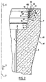
- Figure 1 where we have designated by 1 a pipe according to the invention, having a symmetry of revolution around a longitudinal axis 2, here horizontal, and comprising a tubular barrel 3, longitudinal, delimited towards axis 2, commonly, by a face inner device 4 cylindrical of revolution around this axis.
- the barrel 3 ends in a not shown butt, which may be a female butt or, preferably, a male butt including one example will be described with reference to figure 10 about another pipe according to the invention; in the opposite direction 6, it ends in a female butt 7, which will be described with reference to Figures 1 and 2.
- the barrel 3 is entirely made in a single piece of molded concrete, symmetrical of revolution around axis 2, including at its two ends.
- face 4 continues in direction 5 up to a front, transverse, end face, which is approximately planar, annular of revolution around axis 2 and turned in direction 5 as will be deduced from the subsequent description of the figure 10.
- the face 4 is connects to a flat transverse face 8, annular of revolution around axis 2 to which it is perpendicular, this face 8 being turned in the direction 6 and connecting face 4 to an inner peripheral face 9, longitudinal, of the female end 7, which has a form of revolution around axis 2 and comprises four sections 10, 11, 12, 13 which succeed one another in this order, in direction 6, from side 8.
- Sections 10 and 12 are approximately cylindrical of revolution around axis 2 but slightly flared in your direction 6 for manufacturing reasons by molding.
- the section 12 has a minimum diameter greater than the diameter maximum of the section 10, and the section 11 constitutes between them a section of transition, approximately frustoconical of revolution around axis 2 with a more marked flare than that of sections 10 and 12 in the direction 6.
- the section 13 has a rounded shape convex towards axis 2 and in direction 6, with a section approximately in quarter of circle in a sectional view through a plane including axis 2, and connects the section 12, in direction 6, to a front end face 14 of the female end piece 7, and more generally of the pipe 1 considered as a whole.
- This face 14 is transverse, approximately planar, annular of revolution around axis 2 and turned in direction 6.
- the junction of section 11 with the sections 10 and 12 and the junction of section 10 with the annular face, transverse 8 have the shape of softened edges.
- the inner peripheral face 9 of the end piece female 7 has an annular groove 15 of revolution about the axis 2 and closer, longitudinally, to the section 13 than to the section 11.
- this groove 15 is delimited by a bottom 16 cylindrical of revolution around axis 2 with a diameter greater than that of the junction between the sections 12 and 13 of the inner peripheral face 9, and by two transverse sides 17, 18, one and the other annular of revolution around axis 2, respectively turned in direction 6 for the flank 17 which is closest, longitudinally, to section 11 and in the direction 5 for the sidewall 18 which is closest, longitudinally, to the section 13.
- the flank 18 approximately coincides with the connection between the sections 12 and 13 of the inner peripheral face 9 while the side 17 is located approximately equidistant, longitudinally, from this junction and the junction of the section 12 with the section 11.
- the sidewall 18 is for example plane and perpendicular to axis 2 while the side 17 is not only approximately plane and perpendicular to axis 2 and, preferably, has a slightly frustoconical shape of revolution around this axis and widening in direction 6, as will be deduced from the description, subsequent, of the arrangement of the groove 15 in the female end 7 to manufacturing the pipe 1.
- the bottom 16 thereof is hollowed out, in the direction of a distance from axis 2, an annular groove 19 of revolution around the axis 2 and having a dovetail section in the example shown, when viewed in section through a plane including axis 2, it being understood that one could choose any other section, for example in the shape of a rectangle, of a regular polygon or irregular, or even in a circle, since this section would allow anchoring, in the concrete of pipe 1, a corresponding anchoring part 20, also annular of revolution around the axis 2, of an annular seal, transverse 21 able to present several conformations in which it generally retains symmetry of revolution around axis 2.
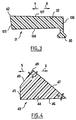
- the anchoring part 20 of the joint 21 has a section strictly complementary to that of groove 19, when viewed in section through a plane including axis 2, so as to anchor the joint 21 in the concrete constituting the pipe 1, and the joint 21 also has, integrally with this anchoring part 20 by making it in a single part with the latter, a sealing part 22 whose section through a plane including axis 2 is strictly complementary to that of groove 15 when the seal 21 occupies a rest position in which, as it is illustrated in Figure 2, its sealing portion 22 is fully retracted to the interior of the groove 15 relative to a geometric extension 23 of the section 12 of the inner peripheral face 9 opposite the groove 15 and, more precisely, this geometrical extension is flush 23.
- groove 19 and the anchoring part 20 are located in the respective areas of the bottom 16 of the groove 15 and the seal 21 which are closest to the end face 14 of the female end 7.
- the rest position of the seal 21, illustrated in Figure 2 constitutes a stable position, that the seal 21 takes when it is subject to no constraints, in particular bending of its part sealing 22 with respect to its anchoring part 20, and towards which it tends to return by elasticity if it is deformed from this position. If like will appear later, the seal 21 is installed in slight elastic stress of circumferential traction, this rest position can also constitute an unstable position, that the seal 21 tends to leave by elasticity to assume a stable position in which its sealing part 22 shrinks slightly in direction 5, forming a slight projection relative to the geometric extension 23 of the section 12 of the inner peripheral face; a person skilled in the art will easily adapt the description which will follow, made with reference to the illustrated example.
- the section of the sealing zone 22 of the joint 21, by a plane including the axis 2, not visible in this figure 3, is approximately rectangular but slightly flared, by spacing mutual of faces 124 and 127, in direction 5, just as it widens in the direction of approximation with respect to axis 2 by spacing the face 125 with respect to face 126.
- a support 23 is deposited on a horizontal surface.
- a formwork ring 24 of known type convex upwards, having a general form of revolution around axis 2 and complementary to that of the faces 8, 9 and 14 of the female end piece to be produced.
- this ring 24 presents upwards, in a direction which corresponds to direction 5 for the pipe to be produced, an annular face, transverse 25, turned in direction 5 and having a shape closely complementary to that of the front face 14 to be produced.
- face 25 is connected to a peripheral face outer 26, longitudinal, of the ring 24, which is turned in the direction of distance from axis 2, protrudes in direction 5 with respect to the face 25 and has a closely complementary shape that of the inner peripheral face to be produced.
- this face 26 has sections 27, 28, 29, 30 which follow one another in this order, in direction 5, from its connection with face 25 and which are respectively complementary to the sections 13, 12, 11, 10 of the face inner device 9; with particular regard to the section 28, it is closely complementary to section 12, apart from throat 15, that is to say it is in particular complementary to the geometric extension 23 of the section 12.
- the outer peripheral face 26 is connected to a flat face 31 perpendicular to the axis 2, turned in the direction 5 and complementary to side 8 in the most distant area of this face 31 axis 2, i.e. in its annular zone closest to its connection with the outer peripheral face 26.
- the joint 21 it has, in one piece, an extension longitudinal 35 opposite its part 22 relative to its part 20, this extension being shaped so as to marry the section 27 by the flank 126 then convex and thus form the stop for immobilizing the seal 21 in the longitudinal position on the shuttering ring 24.
- the groove 15 for receiving the seal 21 in the rest position has a shape slightly different from that which has been described with reference to FIGS. 1 and 2 in that it extends longitudinally, through its bottom 16, beyond from the groove 19 to the section 13 of the inner peripheral face 9 of the female end 7, and that it has no side 18, as will be understood easily a skilled person.
- a molding mandrel 36 delimited, in the direction of a distance from axis 2, by an outer peripheral face 37 cylindrical of revolution around this axis 2 with a diameter identical to that of side 4 to be produced. Furthermore, it is deposited on the surface 23, around of the ring 24, a formwork 38 having towards the axis 2, around the ring 24 and of the mandrel 36, an inner peripheral face 39 having a shape of revolution around axis 2, complementary to that of a face external device 40 of the pipe 1 to be produced; the shape of this face 40 being indifferent with regard to the present invention, it will not be described more, as well as the shape of the face 39.
- the mandrel 36 and the formwork 38 thus define, by their faces 37 and 39, with the faces 25 and 26 of the ring 24 and with an annular zone of its face 31, adjacent to face 26, a molding imprint 140 of shape closely complementary to that of pipe 1 to be produced in the state intermediate thereof illustrated in FIG. 2, and in which the seal 21, in rest position, occupies a position corresponding to its final position with respect to the pipe 1 to be produced, at least in this intermediate state of this one. If necessary, in the upper part, the formwork 38 can be completed to properly conform the male end of the hose.
- the mold formed by the ring 24, the mandrel 36 and the formwork 38 is vibrated during the introduction of the concrete, and one uses relatively dry concrete, quickly providing sufficient cohesion so that the assembly formed by the concrete and the joint 27, resting on the ring 24, has a stability of shape such that one can quickly remove the mandrel 36 and the formwork 28, then let the concrete finish setting and the case if necessary cause this setting while the aforementioned assembly rests in vertical position on the ring 24, which is then removed.
- seal 21 has been put in slight elastic tensile stress circumferential on the timing ring, it then tends to be released from the groove 15 by narrowing in direction 5, by pivoting of part 22, which tends to shrink from its part 20, meanwhile now trapped in groove 19, but part 22 nevertheless remains housed in the less for the most part in the throat 15 so that we will neglect this trend thereafter.
- This next phase of the process consists in release from the groove 15 at the part 22 of the seal 21, by elastic deformation of the latter and, in particular, pivoting of its sealing part 22 towards the axis 2 relative to the anchoring part 20, so that this part 22 protrudes towards the axis 2, out of the groove 15, relative to the geometric extension 23 of the section 12.
- a suitable tool not illustrated, by means of which leverage is exerted on the part 22 of the joint 21, at the level of the face 125.
- the seal 21 can thus bring the seal 21 to an active position, that is to say a position in which it is likely to come to bear sealing against an antagonistic peripheral face of a male butt, in conditions which will be described with reference to Figure 10.
- the faces 124 and 127 of the seal 21 have a frustoconical shape of revolution around axis 2 and converge in direction 5, i.e. make projection towards axis 2 with respect to the geometric extension 23 of the section 12 by gradually moving away from this geometric extension in the direction 5, as illustrated in FIG. 1, and the part 22 of the seal 21 has opposite the anchoring part 20 in direction 5 a free edge 42, at the junction of faces 125 and 127, which free edge 42 constitutes the joint area 21 then closest to the axis 2 to establish the aforementioned sealing support.
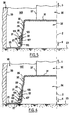
- a wedge ring 43 elastically compressible, transverse, annular revolution around axis 2.
- the ring 43 comprises, by being made in one piece, a heel 44 which, respectively in direction 5 and in the direction of a distance from to axis 2, is delimited by a transverse annular face 45, of revolution around axis 2, having a shape substantially complementary to that of the flank 17 of the groove 15 or, at least, likely to take easily such a shape due to the elastic compressibility of the heel 44, and by a cylindrical peripheral face 46 of revolution around the axis 2 with a diameter identical to that of the bottom 16, so as to marry respectively the face 17 and the bottom 16.
- the face 46 of the heel 44 extends, in the direction 6, up to proximity immediate of the groove 19, at which it is connected to a face 47 frustoconical of revolution about axis 2, converging in direction 5 and turned both in direction 6 and towards axis 2 with an inclination identical to that of the face 124 of the seal 121 in the active position so as to serve as support, in direction 5 and in the direction of a distance from axis 2, at this face 124 of the seal 21 in the active position, as illustrated in Figure 1.
- the ring 43 considered in a state of absence of elastic stress or rest, as illustrated in Figure 4, is dimensioned so that its face 47 extends towards axis 2 beyond the geometric extension 23 of the section 12 of the peripheral face inner 9 of the female end 7, that is to say offers the face 124 a support on the major part of the surface of this face 124, as illustrated in the figure 1.
- the face 47 is advantageously ends with a circular edge 48, centered on the axis 2 and transverse with respect to it, which edge 48 materializes the limit of the ring 43 in the direction of approximation with respect to the axis 2, that is to say the maximum projection thereof relative to the geometric extension 23 of section 12 in the example illustrated, as well as the limit of mutual support faces 124 and 47.
- the edge 43 is thus located much more near the junction between the faces 125 and 127 of the sealing part 22 of the joint 21 that of the anchoring part 20 thereof; however, this does not constitute than a nonlimiting example and depending on the desired effect on part 22 of the seal 21, this edge 48 could be in any position between the mutual joining of the faces 124 and 125 of the part 22 of the joint 21 and inside the throat 15.
- the face 47 of the ring 43 is connected to a face 49 of this one, which is frustoconical of revolution around the axis 2 with a obliquity opposite to that of face 47, in the example illustrated, and connects the edge 48 to face 45, to which this face 49 is connected at the level of the geometric extension 23 of the section 12 of the peripheral face inner 9 of female end 7.
- the acute angle ⁇ formed between them by faces 47 and 46 of the ring 43 can be of the order of 40 ° and the angle ⁇ that form between them the faces 47 and 49, around the edge 48, can be of around 90 °, but these figures are only given as an example, not limiting.
- the respective shapes of the seal 21 and the ring of wedging 43, in the respective rest position, and the corresponding shape of the groove 15 are only non-limiting examples with respect to to which many variants can be provided when these forms are suitable for ensuring that the seal 21 is flush with the section 12 of the inner peripheral face 9 of the female end piece 7 in the rest position and then inserting and holding the wedging ring 43 in the groove 15 to resiliently retain the seal 21 in the active position in which, on the contrary, it projects towards axis 2 with respect to the extension geometric 23 of the section 12 of the inner peripheral face.
- the respective constituent materials of the seal 21 and of the ring setting 43 can also be chosen from a wide range of possibilities, on the one hand in terms of hardness of these materials and on the other hand in terms of the nature of these same materials.
- the pipe 51 including at its male butt 50, has an inner peripheral face 53 of cylindrical revolution around axis 2 with a diameter identical to that of the peripheral face inner 4 of pipe 1 and, in direction 5, this inner peripheral face 53 is connected to a transverse, flat, annular end face 54 of revolution around axis 2 to which it is perpendicular.
- This face 54 turned in direction 5, connects in the direction of a distance by relative to the axis 2 to an outer peripheral face 55 of the male end piece 50, which is turned in the direction of a distance from axis 2 and presents, from its connection with the front face 54, two sections 56, 57 which follow one another in the direction 6.
- the section 56 is frustoconical of revolution around axis 2, from which it moves away in direction 6, and represents only a small part of the longitudinal dimension of the face 55.
- the section 57 practically cylindrical of revolution around axis 2 but widening slightly in direction 6 for reasons manufacturing by molding, represents the major part of the longitudinal dimension of the face 55 and is connected in the direction 6 to a third section 58 of the outer peripheral face 55 of the male end 20, which section 58 is concave and gradually moves away from the axis 2 in direction 6, until it is connected to an external peripheral face 59, for example identical to the outer peripheral face 40 of the pipe 1.
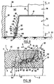
- the female 7 and male 50 ends are dimensioned, longitudinally and transversely to axis 2, such that so that we can fit them together, in a relationship of coaxiality at least approximate, up to a position which is illustrated in the Figure 10 and in which the face 54 is located longitudinally opposite of the face 8 while preserving a clearance with respect to the latter, the section 56 of the face 55 is placed transversely opposite the section 10 of the face 9 however respecting a clearance with respect to the latter, the section 57 is placed transversely opposite the section 12 without contact with it, and the section 58 is placed transversely and longitudinally opposite section 13 but without contact therewith.
- the free edge 42 of the part 22 of the seal 21 is in support, towards the axis 2, on an area of the section 55 of the face 57 which is longitudinally closest to the section 58, and this support results in an elastic deflection of the part 22 of the seal 21 in the direction of a distance from axis 2, and by placing the ring 43 in elastic compressive stress between the part 22 of the joint 21, of a hand, the flank 17 and the bottom 16 of the groove 15, on the other hand, which establishes between the free edge 42 and the section 55 of the outer peripheral face 57 a specific support constraint to create the seal at this level.
- the male end piece 50 is also produced in accordance with the present invention and present in a manner which does not will not be detailed but could be easily deduced by a man of loom, from the description of the female end piece 7, a groove 60, annular of revolution around axis 2, located in section 55 nearby immediate connection of the latter with the section 56 and having, when viewed in section through a plane including axis 2, a section which can be identical to that of groove 15 which was previously described, including understood as to the layout, in the area of this gorge 60 which is the closer, longitudinally, to the front face 54, to a groove 61, annular of revolution around axis 2, presenting when viewed in cut by a plane including this axis a dovetail section or any another section suitable for permanent anchoring of a joint 62 in all point comparable to seal 21.
- this seal 62 like the seal 21, has a part 63 anchor in groove 61, closely matching it which it spares advantageously in the concrete constituting the male end piece 50 during the molding thereof, and a sealing part 64 capable of occupying a rest position, not shown, in which it is fully integrated into the groove 60 by being flush with the geometric extension 65 of the section 55, the sealing part 64 in the rest position being advantageously used during the molding of the concrete to conform the groove 60 in addition.
- the sealing part 64 of the seal 62 is however placed in an active position, in which it projects in the direction of a distance from axis 2, from the geometric extension 65 of the section 55, by insertion, partly in the groove 60, a wedging ring 66 providing support in the direction 6 in this active position, and at all points comparable to the timing ring 43.
- the wedging member 66 retains the part 64 of the seal 62 in sealing support, in the direction of a distance from axis 2, against section 12 of the face inner peripheral 9 of the female end 7, by means of a bending of this sealing portion 64 in the direction of approximation with respect to axis 2, accompanied by an elastic compression effect of the ring of wedging 66 by the sealing part 64 of the seal 62, towards the inside of the groove 60.
- the joint 64 stressed by the timing ring 66 is supported, in the same way, on the section 12 of the inner peripheral face 9 of the female end 7, but the two butts 7 and 50 are dimensioned longitudinally so that the seal 64 and its timing ring 66 are then offset in direction 5 by relative to the seal 21 and its timing ring 43, that is to say so that the seal 64 rests on the section 12 between the groove 15 and the section 11.
- the maximum projection that the ring 43, 66 forms transversely relative to the extension geometric 23, 65 of the section 12, 55 of the peripheral face should be greater than that formed by the seal 21, 62 in the active position to allow the sealing support of the ring 43, 66 against the peripheral face 55 or 9.
- FIG. 11 illustrates an embodiment of the invention in which, thus, the timing rings 43, 46, produced in the form waterproof, play a role in sealing and in which, on the other hand, the seals 21, 62, also produced in sealed form, retain a role in this tightness.
- each setting ring 43, 66 has a longitudinal extension 67, 68, respectively in direction 5 and in direction 6, on which the joint 62, 21 can thus be supported respectively in the direction of a distance by in relation to axis 2 and in the direction of approximation with respect thereto by means of an elastic deflection of the two joints 62, 21 and a elastic compression of the two timing rings 66, 43, in conditions suitable for ensuring a relative seal.
- the longitudinal extension 67 of the ring setting 43 in direction 5 is delimited, from edge 38 in direction 5, by an inner peripheral face 69 serving as a sealing support for the seal 62 and having a cylindrical shape of revolution around the axis 2 in the absence of elastic compressive stress applied for example by this joint.
- this inner peripheral face 69 is connected to a flat annular face 70, turned in direction 5 and having a shape annular of revolution around the axis 2, to which this face 70 is perpendicular.
- the face 70 thus connects the inner peripheral face 69 of the extension 67 of the timing ring 43 to a peripheral face outer 71 of this extension, which is approximately cylindrical of revolution around axis 2 with a diameter such that, by elasticity, it follows the section 12 of the inner peripheral face of the female end 7 between the groove 15 and the section 11, and is connected to the face 45 of the timing ring 43 in the direction 6.
- the longitudinal extension 68 timing ring 66 has a similar conformation, to serve sealing support 21.
- each of the extensions 67 and 68 presents, at its face such as 69, a dimension L at least equal, and of preferably greater than that of the possible longitudinal travel between the pipes or the like 1, 51 after their laying, namely to that I of the distances separating respectively the faces 54 and 8 and the sections 58 and 13 which is the weaker.
- seals such as 21 and 62 in the rigid component of pipes or the like when this component is already rigid, and in particular made of a material other than a material curable initially presenting in the fluid state, that is to say in a material such that the molding conditions do not lend themselves to direct integration of seals such as 21 and 62, as may be the case when the pipes or the like in accordance with the present invention are by example metallic and manufactured by molding at temperatures which may cause deterioration of the seals.
Landscapes
- Engineering & Computer Science (AREA)
- Mechanical Engineering (AREA)
- General Engineering & Computer Science (AREA)
- Manufacturing & Machinery (AREA)
- Chemical & Material Sciences (AREA)
- Ceramic Engineering (AREA)
- Joints With Sleeves (AREA)
- Quick-Acting Or Multi-Walled Pipe Joints (AREA)
- Rigid Pipes And Flexible Pipes (AREA)
Applications Claiming Priority (2)
| Application Number | Priority Date | Filing Date | Title |
|---|---|---|---|
| GB9911322A GB2350082A (en) | 1999-05-15 | 1999-05-15 | A concrete pipe having a sealing member |
| GB9911322 | 1999-05-15 |
Publications (2)
| Publication Number | Publication Date |
|---|---|
| EP1054204A2 true EP1054204A2 (de) | 2000-11-22 |
| EP1054204A3 EP1054204A3 (de) | 2002-08-07 |
Family
ID=10853530
Family Applications (1)
| Application Number | Title | Priority Date | Filing Date |
|---|---|---|---|
| EP00401323A Withdrawn EP1054204A3 (de) | 1999-05-15 | 2000-05-15 | Rohr, insbesondere aus Beton, mit einer Dichtung und ein Verfahren zur Herstellung eines derartigen Rohrs |
Country Status (2)
| Country | Link |
|---|---|
| EP (1) | EP1054204A3 (de) |
| GB (1) | GB2350082A (de) |
Cited By (2)
| Publication number | Priority date | Publication date | Assignee | Title |
|---|---|---|---|---|
| US10018043B2 (en) | 2014-05-06 | 2018-07-10 | Trelleborg Ridderkerk B.V. | Method for producing a construction element, in particular a tunnel element, having a watertight seal |
| WO2023232101A1 (zh) * | 2022-06-02 | 2023-12-07 | 郝百顺 | 混凝土管 |
Family Cites Families (8)
| Publication number | Priority date | Publication date | Assignee | Title |
|---|---|---|---|---|
| BE790520A (fr) * | 1971-10-25 | 1973-02-15 | Forsheda Ideutveckling Ab | Section de tuyau, de preference en beton avec bague d'etancheite |
| BE794815A (fr) * | 1972-01-31 | 1973-05-16 | Forsheda Ideutveckling Ab | Article en un materiau elastique et muni de dispositifs de renforcement |
| DE3136322A1 (de) * | 1981-09-12 | 1983-03-24 | Denso-Chemie Wedekind Kg, 5090 Leverkusen | Dichtungsanordnung fuer eine muffenverbindung an rohren |
| DE3219522A1 (de) * | 1981-10-28 | 1983-12-01 | Denso-Chemie Wedekind Kg, 5090 Leverkusen | Steckmuffendichtung fuer rohre |
| DE3642880A1 (de) * | 1986-12-16 | 1988-06-30 | Muecher Hermann Gmbh | In die muffenwand eines rohres einbetonierte steckdichtung |
| DE3801748A1 (de) * | 1988-01-22 | 1989-07-27 | Phoenix Ag | Steckmuffendichtung |
| DE4229609C2 (de) * | 1992-09-04 | 2003-05-08 | Forsheda Stefa Gmbh | Abdichtung zwischen zwei ineinandersteckbaren Teilen |
| DE9212666U1 (de) * | 1992-09-21 | 1993-11-04 | PT-Poly-Tec GmbH Vertrieb und Herstellung von Dichtungssystemen, 63456 Hanau | Abdichtung zwischen zwei ineinandersteckbaren Teilen |
-
1999
- 1999-05-15 GB GB9911322A patent/GB2350082A/en not_active Withdrawn
-
2000
- 2000-05-15 EP EP00401323A patent/EP1054204A3/de not_active Withdrawn
Cited By (3)
| Publication number | Priority date | Publication date | Assignee | Title |
|---|---|---|---|---|
| US10018043B2 (en) | 2014-05-06 | 2018-07-10 | Trelleborg Ridderkerk B.V. | Method for producing a construction element, in particular a tunnel element, having a watertight seal |
| EP3140512B1 (de) * | 2014-05-06 | 2023-03-22 | Trelleborg Ridderkerk B.V. | Verfahren zur herstellung eines bauelementes, insbesondere eines tunnelelements, mit wasserdichter abdichtung |
| WO2023232101A1 (zh) * | 2022-06-02 | 2023-12-07 | 郝百顺 | 混凝土管 |
Also Published As
| Publication number | Publication date |
|---|---|
| EP1054204A3 (de) | 2002-08-07 |
| GB9911322D0 (en) | 1999-07-14 |
| GB2350082A (en) | 2000-11-22 |
Similar Documents
| Publication | Publication Date | Title |
|---|---|---|
| EP0704251B1 (de) | Ring, Vorrichtung und Verfahren zum Befestigen einer Kappe an einem Behälter | |
| EP0979332B1 (de) | Verfahren zur herstellung vorfabrizierter bauelemente und vorgespannte baukonstruktion aus solchen elementen hergestellt | |
| EP0310534B1 (de) | Dichtungsring für feste Teleskopverbindungen | |
| EP0811113B1 (de) | Dichtung und ihr herstellungsverfahren | |
| EP2140459B1 (de) | Container zum transportieren und/oder lagern von kernmaterialien mit einer aus auf eine metallverstärkung gegossenem blei hergestellten radiologischen abschirmung | |
| EP1612443B1 (de) | Kupplungsausrücklager und Verfahren zu seiner Herstellung. | |
| WO2015118401A1 (fr) | Gaine tubulaire annelée comportant un moyen intérieur de serrage | |
| FR2548708A1 (fr) | Garniture d'etancheite a manchon d'emboitement pour tuyaux en beton comportant un element d'etancheite fixe sur la cloche de tuyau | |
| EP1217283B1 (de) | Rohr oder ähnliches; weiblicher Abschlussring und Herstellungsverfahren eines solchen Rohres oder ähnlichem | |
| EP1054204A2 (de) | Rohr, insbesondere aus Beton, mit einer Dichtung und ein Verfahren zur Herstellung eines derartigen Rohrs | |
| FR2712655A1 (fr) | Joint d'étanchéité. | |
| FR2647165A1 (fr) | Systeme d'assemblage d'un premier element, tel qu'une arete de guidage, a un second element tel qu'un ski de fond, cheville et arete de guidage destinees a un tel systeme d'assemblage | |
| EP3643469A1 (de) | Form für betonbauteile mit einsatz | |
| EP1560984B1 (de) | Stützvorrichtung für schienen eines schotterlosen gleisoberbaus | |
| EP0497721A2 (de) | Verfahren zur Herstellung eines Grabgewölbes oder eines Grabgewölbe-Elementes und danach erhaltenes Grabgewölbe | |
| FR3041672B1 (fr) | Coque de piscine en matiere plastique pourvue d'elements de renfort | |
| WO2002040295A1 (fr) | Procede de fabrication d'une jante de bicyclette prevue pour un montage sans chambre a air et jante obtenue par la mise en oeuvre du procede | |
| FR2742796A1 (fr) | Procede de realisation d'un anneau de voussoirs, anneau de voussoirs obtenu, cache pour la mise en oeuvre du procede et voussoir destine a cooperer avec un tel cache | |
| FR2840330A1 (fr) | Procede de realisation d'une traverse de chemin de fer, traverse de chemin de fer susceptible d'etre realisee au moyen de ce procede | |
| EP4164807B1 (de) | Befestigungselement für eine dosierpumpe | |
| FR2695589A1 (fr) | Procédé de fabrication par moulage d'éléments creux tels que des éléments de canalisation en béton à joint d'étanchéité intégré, et dispositif pour la mise en Óoeuvre de ce procédé. | |
| EP1867882B1 (de) | Verankerungsvorrichtung mit Flügeldübeln | |
| BE517877A (de) | ||
| FR2623536A1 (fr) | Procede de prefabrication d'un regard de coulee composite et regard de coulee | |
| FR2598773A1 (fr) | Bague d'etancheite pour tuyaux a emboitement. |
Legal Events
| Date | Code | Title | Description |
|---|---|---|---|
| PUAI | Public reference made under article 153(3) epc to a published international application that has entered the european phase |
Free format text: ORIGINAL CODE: 0009012 |
|
| AK | Designated contracting states |
Kind code of ref document: A2 Designated state(s): AT BE CH CY DE DK ES FI FR GB GR IE IT LI LU MC NL PT SE |
|
| AX | Request for extension of the european patent |
Free format text: AL;LT;LV;MK;RO;SI |
|
| PUAL | Search report despatched |
Free format text: ORIGINAL CODE: 0009013 |
|
| AK | Designated contracting states |
Kind code of ref document: A3 Designated state(s): AT BE CH CY DE DK ES FI FR GB GR IE IT LI LU MC NL PT SE |
|
| AX | Request for extension of the european patent |
Free format text: AL;LT;LV;MK;RO;SI |
|
| AKX | Designation fees paid | ||
| REG | Reference to a national code |
Ref country code: DE Ref legal event code: 8566 |
|
| STAA | Information on the status of an ep patent application or granted ep patent |
Free format text: STATUS: THE APPLICATION IS DEEMED TO BE WITHDRAWN |
|
| 18D | Application deemed to be withdrawn |
Effective date: 20030208 |