EP0704355A1 - Warnsirene für Fahrzeugalarmzentrale - Google Patents
Warnsirene für Fahrzeugalarmzentrale Download PDFInfo
- Publication number
- EP0704355A1 EP0704355A1 EP95115044A EP95115044A EP0704355A1 EP 0704355 A1 EP0704355 A1 EP 0704355A1 EP 95115044 A EP95115044 A EP 95115044A EP 95115044 A EP95115044 A EP 95115044A EP 0704355 A1 EP0704355 A1 EP 0704355A1
- Authority
- EP
- European Patent Office
- Prior art keywords
- alarm
- module
- siren
- terminal
- message
- Prior art date
- Legal status (The legal status is an assumption and is not a legal conclusion. Google has not performed a legal analysis and makes no representation as to the accuracy of the status listed.)
- Withdrawn
Links
- 238000001514 detection method Methods 0.000 claims description 14
- 230000033228 biological regulation Effects 0.000 claims description 6
- 238000004140 cleaning Methods 0.000 claims description 5
- 238000012544 monitoring process Methods 0.000 claims description 5
- 239000003990 capacitor Substances 0.000 description 16
- 238000010586 diagram Methods 0.000 description 9
- 230000006870 function Effects 0.000 description 8
- 230000004913 activation Effects 0.000 description 5
- 230000001105 regulatory effect Effects 0.000 description 5
- 230000010287 polarization Effects 0.000 description 4
- 230000003321 amplification Effects 0.000 description 3
- 230000008901 benefit Effects 0.000 description 3
- 230000005540 biological transmission Effects 0.000 description 3
- 230000008859 change Effects 0.000 description 3
- 238000003199 nucleic acid amplification method Methods 0.000 description 3
- 230000002618 waking effect Effects 0.000 description 3
- 241000269400 Sirenidae Species 0.000 description 2
- 230000000694 effects Effects 0.000 description 2
- 238000001914 filtration Methods 0.000 description 2
- 239000011521 glass Substances 0.000 description 2
- 230000001939 inductive effect Effects 0.000 description 2
- 230000007246 mechanism Effects 0.000 description 2
- 244000045947 parasite Species 0.000 description 2
- 230000000630 rising effect Effects 0.000 description 2
- 230000005236 sound signal Effects 0.000 description 2
- 238000012360 testing method Methods 0.000 description 2
- 230000001960 triggered effect Effects 0.000 description 2
- 208000032953 Device battery issue Diseases 0.000 description 1
- 241001465382 Physalis alkekengi Species 0.000 description 1
- 230000003213 activating effect Effects 0.000 description 1
- 230000001276 controlling effect Effects 0.000 description 1
- 230000009849 deactivation Effects 0.000 description 1
- 230000007423 decrease Effects 0.000 description 1
- 238000007599 discharging Methods 0.000 description 1
- 239000006185 dispersion Substances 0.000 description 1
- 238000009826 distribution Methods 0.000 description 1
- 238000005265 energy consumption Methods 0.000 description 1
- 235000021183 entrée Nutrition 0.000 description 1
- 230000036039 immunity Effects 0.000 description 1
- 230000002779 inactivation Effects 0.000 description 1
- 230000005764 inhibitory process Effects 0.000 description 1
- 238000009434 installation Methods 0.000 description 1
- 238000012423 maintenance Methods 0.000 description 1
- 238000004519 manufacturing process Methods 0.000 description 1
- 238000000034 method Methods 0.000 description 1
- 239000000203 mixture Substances 0.000 description 1
- 230000000737 periodic effect Effects 0.000 description 1
- 230000008439 repair process Effects 0.000 description 1
- 230000007704 transition Effects 0.000 description 1
Images



Classifications
-
- B—PERFORMING OPERATIONS; TRANSPORTING
- B60—VEHICLES IN GENERAL
- B60R—VEHICLES, VEHICLE FITTINGS, OR VEHICLE PARTS, NOT OTHERWISE PROVIDED FOR
- B60R25/00—Fittings or systems for preventing or indicating unauthorised use or theft of vehicles
- B60R25/10—Fittings or systems for preventing or indicating unauthorised use or theft of vehicles actuating a signalling device
- B60R25/1003—Alarm systems characterised by arm or disarm features
-
- G—PHYSICS
- G08—SIGNALLING
- G08C—TRANSMISSION SYSTEMS FOR MEASURED VALUES, CONTROL OR SIMILAR SIGNALS
- G08C25/00—Arrangements for preventing or correcting errors; Monitoring arrangements
Definitions
- the present invention relates to an alarm siren for a vehicle alarm center. It also relates to an alarm center thus equipped.
- alarm centers are already known which are equipped with intrusion sensors such as ultrasonic sensors or glass break detectors or even presence detectors, which are connected to a generator module. '' an alarm signal when an alarm condition is fulfilled. Such an alarm signal is generally transmitted to an alarm siren located far enough from the alarm center to make any sabotage of such installations more difficult.
- remote alarm sirens are generally of the self-powered type, that is to say, they are connected to the vehicle battery on the one hand, and to internal accumulators on the other hand.
- Such alarm sirens are provided with means for detecting sabotage of the supply line to the vehicle battery, so as to pass over the internal accumulators and cause an alarm signal to be emitted warning of sabotage.
- the alarm center is connected to the alarm siren by a link that activates the alarm siren when an alarm condition has been verified.
- a link that activates the alarm siren when an alarm condition has been verified.
- the alarm center is connected to the input of the self-powered siren so as to put it either in a standby state or in a stop state, by applying a determined level voltage on this entry.
- the voltages on the siren input have different levels depending on the meaning of the command (stop / standby) produced by the alarm center.
- the standby state an alarm signal can come in and be decoded by the siren that rings.
- the stop state the siren can no longer sound, even if an alarm state is received by the siren, or if an alarm state is detected internally by the self-powered siren itself.
- the present invention provides a new self-powered alarm siren, which is protected from sabotage on the one hand, and which improves the management of communications between the alarm center and the siren itself, on the other hand go.
- the present invention relates to an alarm siren of the type comprising a means of connection with an alarm center, for exchanging control and / or status information.
- the invention is characterized in particular in that the alarm center comprises a module generating a coded message which is transmitted on the connection means and continuously repeated until a change of command.
- the alarm siren comprises a module for receiving the coded message, the output of which is connected to a module for controlling the siren, provided with means for detecting non-repetition of the coded messages transmitted on the link means. the output of which activates a sound module.
- the message is coded, for example according to a coding known only to the alarm center and the siren, provides great protection against sabotage, since a thief can no longer simulate the presence of the central for present a stop command to the siren without first knowing this coding.
- the non-repetition detection means comprises a wake-up circuit of the "watch-dog" type.
- This latter arrangement has the advantage of allowing the electronic circuits of the siren to go to sleep between two repetitions of the control signal, so that the electrical consumption is reduced. It is a considerable advantage to reduce the electrical consumption of a motor vehicle alarm system and its siren, insofar as such a system is made to remain in the standby state for long periods of time. , and where the power source (vehicle battery) has a capacity which, by nature, is limited.
- the siren control module includes means for decoding a command carried by the coded message sent on the link means and taken from a predetermined set of commands produced by the central control unit. alarm for actuation of the sound module. It is thus possible to increase the functionality of the siren.
- the message comprises a start bit and a duration bit, the duration of which determines the duration of the useful part of the coded message, the useful part of the coded message comprising a predetermined number of data bits.
- the alarm siren comprises means for transmitting an acknowledgment message, after receipt of each change of message, a received message being considered to be new if it is different from the previous one and if it is received consecutively a predetermined number of times, received, preferably three times.
- the generator module comprises a means of receiving the acknowledgment of receipt, which in the absence of reception of such an acknowledgment of receipt, can produce an alarm signal by means of the vehicle audible warning, in particular.
- the generator is constituted by the series connection of two inverting amplifiers whose inputs are loaded by an RC network, so that the trigger thresholds of the two amplifiers compensate for the differences between the trigger times possible of the monostable thus constituted.
- the siren also comprises an internal supply means constituted by a accumulator and in that it comprises a means of detecting sabotage of the main supply line.
- the siren comprises a transistor whose collector produces an earthing, through a resistor, of the corresponding terminal of the accumulator so as to carry out a rapid charge of the internal accumulator whose the other terminal is connected to the battery supply voltage.
- the siren includes a connection terminal to the wire connecting to the alarm center. It also includes a circuit for cleaning the connection terminal constituted by a transistor, the base of which is connected to an output port of the control module so as to periodically cause a strong current to flow on the connection terminal.
- the alarm siren comprises means for receiving and decoding a code corresponding to the ringing regulation as a function of a code sent by the alarm center via said permanent link.
- the invention also relates to a vehicle alarm center.
- the control unit comprises a module generating a coded message, connected by a permanent link to a remote alarm siren according to the invention.
- an alarm system comprising an alarm center 1 and a remote siren 2.
- the siren is self-powered in order to provide protection against sabotage of the supply line.
- the alarm center 1 is, for example, located behind the dashboard of the protected vehicle. It is connected to ultrasonic sensors 3 arranged in the passenger compartment so as to monitor intrusions and broken glass. The sensors 3 are therefore connected to the input of an alarm condition detector module 4 which has an activation or deactivation input 5 coming from the vehicle access system 6.
- the vehicle access system 6 may include a mechanical key 7 or an electronic key such as a radiofrequency or infrared transmitter. It is used to recognize an authorized person and to allow him to access the vehicle, in particular by unlocking the doors to the vehicle and by making the intrusion alarm center passive.
- the module for decoding an alarm condition 4 produces a signal on an output 8 connected to the input terminal 9 of a module 10 generating a coded message.
- the module 10 is connected by a connecting wire 11 to the alarm siren.
- the alarm siren includes a receiver module 13, an input terminal 12 of which is connected to the connecting wire 11.
- the main power supply of the siren is brought by two wires, respectively 14 for connection to the positive terminal (+), and 15 for connection to the negative terminal (-) of the vehicle battery.
- Battery voltage is distributed to the various components of the alarm siren. If the siren is also self-powered, the battery voltage is also transmitted to a module 16 formed around an internal accumulator which allows self-powering of the siren in case of failure of the main power supply , produced by the vehicle battery, or sabotage of connections 14 and 15.
- the alarm siren 2 also comprises a control module, constituted by a microcontroller 17, standard of the trade, having input / output ports, an interrupt input, and resources such as a read-only memory recording the operating program of the control module and of the random access memory which stores the data being processed.
- the microcontroller 17 monitors the state of the internal accumulator and / or of the main supply 14, 15 so as to switch to rapid recharging of the internal accumulator in the event of discharge. It also includes a programmable memory, containing the configuration information of the alarm siren in its precise environment (type of vehicle, legislation, ). The configuration information is stored in this way in alarm 1 and transmitted to the siren 2 by a different code for each configuration by the coded link. Fast charging is done by command of alarm 1 (specific message) depending on the state of the vehicle battery.
- the microcontroller is connected by an input terminal 18 to the output of the reception module 13. It includes means for decoding the coded message received from the alarm center.
- the coded message represents a command produced by the alarm center according to its predetermined operation. Therefore, the coded message constitutes a command taken from a predetermined set of commands and which are mainly intended to activate or not an audio module 22, 23.
- the microcontroller has an output terminal 19 connected to an acknowledgment transmission circuit 20 which reinjects an acknowledgment message on the connecting wire 11.
- the generator module 10 of the coded message detects the acknowledgment of receipt produced by the alarm siren and informs of the absence or the presence of this acknowledgment of receipt the alarm module 4 by a connecting wire 21.
- the microcontroller 17 is connected by its output terminal 22 to a sound module 23, constituted for example by a piezoelectric vibrator.
- the sound module consists of a diaphragm speaker.
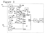
- FIG 2 there is shown a developed block diagram of a preferred embodiment of a self-powered siren according to the invention.
- the self-powered siren of FIG. 2 has a terminal 30 for connection to the connection wire with the alarm center and a wire and a connection terminal 31 connected to a connection cable to the positive terminal of the battery.
- the electrical grounds of the diagram are set to the same potential which is connected to the negative terminal of the vehicle battery.
- the microcontroller 17 is connected to the input terminal 30 of the self-powered siren via an alarm module 33 which is connected to the output terminal of the reception module 32.
- the input terminal of the reception module 32 is connected to terminal 30.
- the wake-up module 33 includes a first input terminal 36 connected to the output terminal of the aforementioned receiver module 32, which is moreover connected to an input port PC0 of the microcontroller 17, and a second input terminal 37 which is connected to the output terminal of a generator 38 for monitoring period (time out), which allows the microcontroller to wake up periodically according to the method known under the term "Watch-dog".
- the alarm module has a first output terminal 34 which is connected to an IRQ input terminal for receiving an interruption request from the microcontroller 17. Furthermore, it also has a third input terminal 35 connected to a PCO serial access port of the microcontroller 17 to allow inhibition of waking up when the microcontroller is awakened.
- the module 38 To activate the "Watch-dog" which serves as a means of detecting non-repetition, the module 38 includes an input terminal 39 which is connected to an output port PA1 of the microcontroller.
- the generator 38 of monitoring period produces after a predetermined time a pulse which is transmitted to the input terminal of the alarm module 33.
- a request is presented on the IRQ input (of the microcontroller which can then test the state of the siren and in particular that of the power supply line 31.
- the microcontroller 17 includes an output port PA4 which is connected to an input terminal 40 of a module 41 generating an acknowledgment signal, which is produced by an output terminal 42 connected to the connection terminal 30 to the connection wire to the alarm center according to a predetermined protocol prerecorded in the microcontroller 17.
- the microcontroller produces an acknowledgment message which is decoded by the control panel for three messages.
- the non-repetition detection means actuates the sound module 57-59 by the output ports PA5, PA6 of the microcontroller 17.
- the non-repetition detection means comprises a predetermined capacity counter, the start of which is ensured by the reception of a coded message.
- a counter activation terminal is connected to an output terminal of the receiver module 13.
- the counter output changes to the active state if the capacity of the counter is exceeded, a terminal for exceeding the capacity of the counter being connected to an output port PA5, PA6 of the microcontroller 17 connected to the sound module.
- the capacity of the meter is predetermined in advance. In another embodiment, it evolves as a function of a table of capacitance values so as to cause the repetition period of the coded messages to evolve in synchronism with the generator module 10.
- the table is stored in the memory of the microcontroller 17 and it is addressed as a function of an addressing parameter such as the arrival of a new message detected by the reception module.
- the non-repetition detection means comprises an external "watch-dog” circuit.
- the microcontroller is placed in standby mode between each message to reduce its electrical consumption.
- the "watch-dog” realizes, as is known, the awakening of the microcontroller, either periodically, or else on a particular event detected as will be seen below.
- the alarm center treats the fault or detects sabotage of the self-powered siren and in this case activates the audible warning device usually located in the vehicle as well as possibly the periodic or flashing lighting of the vehicle's lanterns and lights, so as to indicate an alarm situation.
- the self-powered siren also includes a module 43 which makes it possible to filter and protect the voltage received on the connection terminal 31, voltage produced by the vehicle battery before its distribution to the rest of the circuit.
- the power supply module 43 has a first protected output 44 which produces a voltage of, for example, +12 volts, protected from overvoltages. This voltage protected from overvoltages 12M is connected in particular to the polarization of the components of the receiver module 32.
- the power supply module 43 includes a second output terminal 45 which is protected from filtered overvoltages and which is denoted 12V which is transmitted to the rest of the siren circuit.
- the 12V voltage is connected to a suitable polarity of the internal accumulator. In this way, if the supply fails, for example by sabotage or disconnection of the connection line to the positive terminal (+) of the battery, the terminal 45 is then supplied directly by the internal accumulator 46.
- the connection terminal 31 is also connected to the input terminal 48 of a power line sabotage detection module 49.
- the sabotage detection module 49 is connected by an output terminal 50 to the input terminal 52 of a voltage regulator module 51.
- the voltage regulator 51 comprises a first output terminal 53 which delivers a DC bias voltage of the TTL type electronic circuits, of +5 volts, and which is denoted Vcc.
- the regulator 51 then comprises an internal comparator, the output terminal 53 'of which is connected to an input port PC3 of the microcontroller 17.
- the internal comparator of the regulator 51 has a first input terminal which is connected to the voltage d regulated supply which serves as a reference voltage and a second input terminal connected to the input terminal 52 of tamper detection signal of the module 49.
- the microcontroller When the voltage of the tamper detection signal drops below the reference voltage connected to the first input terminal of the internal comparator to the regulator 51, the output terminal 53 of the regulator goes to low state, which state is detected via the PC3 input port of the microcontroller. In this case, unless the alarm system is deactivated, the microcontroller produces on its output ports PA5 and PA6 a control signal which is transmitted to the sound module consisting of a power supply module 57 whose output 58 sounds a resonator 59.
- the module 57 is preferably constituted by an "H" bridge comprising four switches mounted as a bridge, the voltage coming from the filtered protected terminal 45 of the supply line 43 being placed at one end of the bridge, the other end being placed to earth, and the diagonal of the bridge being connected to the polarization terminals of the siren resonator 59.
- the self-powered siren also includes an electronic module 60 which makes it possible to carry out a hot restart of the microcontroller 17.
- the module 60 for hot start comprises an input terminal 61 which is connected to the output terminal 53 ' 'of the regulator 51 delivering a reset signal ("reset") when the regulated DC supply voltage of the circuit decreases.
- the module 60 has an output terminal 62 which is connected to a terminal of the microcontroller 17.
- a pulse is produced by the warm restart module 60, after the output 53 '' of reset of the regulator 51 has changed 'state, it allows the program counter to be restarted at an address determined in advance so as to restart the initialization and configuration sequences of the self-powered siren during a restart. If there is no pulse, the siren restarts in the state it stopped.
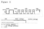
- FIG. 3 the format of the messages exchanged on the connecting wire 11 between the generator module and the receiver module is shown in the self-powered siren.
- FIG 3 there is shown the electrical state of the connection line 11 between the generator module and the receiver module.
- the voltage on the line is constituted by the voltage like the +12 volts of the battery voltage, protected and filtered, voltage produced by the alarm siren.
- the alarm center brings the line voltage to earth as a function of the coded message determined by module 4 ( Figure 1). If there is no message, the line is in the high potential state.
- a transition 70 from the high level to the low level constitutes a wakeup bit for the microcontroller 17 of the self-powered siren transmitted by the receiver 32 and 33. By this wakeup, an interrupt request is triggered on the IRQ terminal of the microcontroller 17 which awakens all the functions of the microcontroller.
- the message duration determination bit then has a rising edge 72, a duration which is between a minimum value and a maximum value.
- the message duration is counted from the rising edge 72 of the end of the duration determination bit. Then, the message develops on a predetermined number of bits whose duration is determined by bit 71.
- the code has five bits.
- a stop bit is generated during which the electrical state of the line remains high.
- an ACK acknowledgment is produced by the self-powered siren in the form of two bits for each code change and for three messages.
- the alarm center deduces that there is no more self-powered siren and then produces a signal of alarm by means of the vehicle horn.
- the protocol which has just been established can be varied in particular by taking into account, no longer falling edges, but durations in the high state on the supply line, or by more complex waveforms, for better immunity to parasites on the line.
- the acknowledgment ACK consists of a retransmission of the message received from the generator module.
- the message includes a large number of possible values which make it possible to code a large number of different commands and which can be recognized by decoding by the self-powered siren.
- the self-powered siren shown in FIG. 3 can be standardized for a whole series of vehicles, the alarm center calling only messages corresponding to functions authorized on the type of vehicle considered.
- the alarm signals that the siren can produce have time-frequency characteristics which vary from country to country. Therefore, it is possible to use the same circuit for all possible vehicles.
- the messages exchanged allow the special use of the self-powered alarm siren, in particular by using a button or an alarm triggering system. anti-aggression, by manipulation for example of a button on the remote control for opening or accessing the vehicle or of a button on the dashboard, which allows the vehicle to be placed in an alarm state.
- the standby messages the inactivation message, and the actual alarm message according to the determined regulations, regulations given by the content of the standby message.
- a waiting period is scheduled during which the microprocessor 31 is in a low waiting consumption state.
- the watchdog mechanism called “watch-dog”, implemented in particular with the generator 38 of monitoring time, wakes up the microcontroller 31 if a new message has not been received.
- the interruption request produced by the generator 38 awakens all of the functions and launches the execution of a routine for starting the siren in sabotage detection mode of the link 11 between the generator and the connection module 32.
- the microcontroller waits on its input port PC0 for the arrival of the first edge of the next bit 71.
- the message decoding routine or the message decoding circuit comprises means for producing a scan of the state of the link line 11 at each instant corresponding to the duration of a bit. Therefore, it is detected whether the current message bit is at one or at zero.
- the message is stored in a register of the microcontroller so as to activate the program corresponding to the decoding of the message.
- the actual receiving module 90 includes a divider resistive bridge consisting of a first resistor 91 and a second resistor 95, a terminal of the first resistor 91 being connected to the input terminal 30 and a common terminal of the resistors 91 and 95 being connected to a first terminal of a capacitor 92.
- the free terminal of resistor 95 is connected to ground.
- the free terminal of capacitor 92 is connected to ground.
- the common point of the resistors 91, 95 and of the capacitor 92 is connected to the input of an amplification chain constituted here by two circuits of the CMOS type supplied by the same supply as the microcontroller.
- the amplification chain is constituted by inverting amplifiers 93, 94 like integrated circuits CD 4049.
- the output of the amplification chain is firstly transmitted to the input 36 of the circuit for transmitting the interrupt request to the microcontroller 31, and secondly transmitted to the input port PC0 of the micro- controller 31.
- the input port PC0 is scanned at the rate determined by the second rate duration of the message as explained below.
- the effect of the components 91, 92, 95 is to reduce the voltage of the link to compatible triggering thresholds and to filter the noise.
- the second module of the reception module 32 is constituted by the transmission circuit of the acknowledgment of receipt.
- the acknowledgment transmission circuit includes a connection to an output port PA4 of the microcontroller on which the pulses appear at 5 volts and which are transformed into voltage pulses adapted to the link line 11, connected to terminal 30.
- the output port PA4 of the microcontroller 31 is connected via a link resistor 97 to the base of an NPN transistor 96, the emitter of which is connected to ground and the collector of which is connected to a first terminal of a resistor 98 the second terminal of which is connected to the connection terminal 30.
- a second resistor 99 is mounted between the + 12M terminal and the connection to the connection terminal 30.
- a filtering capacitor 100 is mounted in parallel on the resistor 99.
- the resistor 99 is used to fix the potential of line 30 ç a high level ("pull-up").
- the transistor 96 operates by switching so as to produce pulses adapted to the link line 11 connected to the link terminal 30.
- the third module 101 for cleaning the contact 30, placed in the connection module 32 of the invention makes it possible to produce periodically during the waking moments, or at predetermined times by programming, a strong current draw which makes it possible to clean the oxide formed on the connecting conductive contact 30.
- the contact cleaning module 101 includes a connection terminal to the output port PA3 of the micro-controller 31.
- the output port PA3 of the micro-controller 31 is connected to the base of an NPN transistor 102 'via a link resistor.
- the emitter of transistor 102 ' is connected to ground and its collector is connected to the base of a second PNP transistor 102.
- the base of the second transistor 102 is connected to the first terminal of a second resistor, the other of which terminal and the transmitter of the transistor 102 are connected to the positive supply of the internal supply circuit 43 of the self-powered siren, terminal referenced 12M.
- the collector of transistor 102 is connected via a resistor 105 to the connection terminal 30 when the pulses produced by the output port PA3 of the microcontroller are produced, transistor 102, which operates in switching mode produces a strong current thanks to the low resistance 105 so as to clean the contact 30.
- FIG 5 there is respectively shown the module 43 for supplying the self-powered siren and the circuit 46 for charging and discharging the battery or accumulator battery allowing self-supply in the event of sabotage or battery failure.
- the power supply module 43 has two terminals 110 and 111 accessible from outside the self-powered siren, which are connected respectively to the connection cables 114 and 113 to the respectively plus and minus terminals of the vehicle battery 115.
- the connecting cables 114 and 113 are conventional cables and which can be disconnected, either for reasons of vehicle maintenance or repair, or else for reasons of sabotage.
- the terminal 111 for connection to the minus terminal of the vehicle battery 115 is connected to the ground 116 of the self-powered siren.
- Terminal 110 is connected to a first terminal of a varistor 117, the other terminal of which is connected to the ground of the siren.
- the common point of terminal 110 and the first terminal of the varistor 117 is output from the power supply module 113 on a terminal 42 placed at the voltage of +12 volts protected from overvoltages by the varistor 117, the effect of which is d '' clipping the sudden voltage surges produced in particular by starting or disconnecting inductive loads on the vehicle battery.
- the aforementioned common point is connected to the anode of a diode 119, the cathode of which is connected on the one hand to a first terminal of a capacitor 119, the other terminal of which is connected to ground at an output terminal 45 producing a filtered 12 volt twist also referenced to 12V for the rest of the circuit, and to a first terminal of a resistor 120.
- the second terminal of the resistor 120 is connected on the one hand to a first terminal of an electrolytic capacitor 121 the other terminal of which is connected to the ground of the self-powered siren, and on the other hand to the cathode of a Zener diode 122, the anode of which is connected to the ground of the siren, and finally to a first terminal of a capacitor 123 and to an output terminal 124.
- the other terminal of the capacitor 123 is connected to the ground of Mermaid.
- the output terminal 124 is therefore placed at a voltage of +12 volts protected from overvoltages, and filtered and limited to the Zener voltage. It is then transmitted to the input of regulator 51 of the siren.
- the module 46 is connected to terminal 45 at a voltage of +12 volts, protected against overvoltage and filtered.
- Terminal 45 is connected to the positive terminal of the internal accumulator 125, the negative terminal of which is connected to a weld rafter 126 which makes it possible to have the accumulator disconnected during the test.
- the negative terminal of the internal accumulator 125 is connected to a circuit consisting of resistors, diodes and transistors allowing a slow charge or a fast charge when the internal accumulator 125 is at an insufficient voltage.
- the internal accumulator 125 In slow charge, the internal accumulator 125 is connected by its negative terminal to ground via a resistor 127 for limiting current. Therefore, the internal accumulator 125 can be charged at a voltage at most equal to the minimum voltage accepted on vehicle batteries such as the battery 115. In a preferred embodiment, this minimum voltage is 7.1 volts. Thus, as soon as the vehicle battery 115 is at a voltage lower than 7.2 volts, it is the internal accumulator 125 which supplies the voltage at terminal 45 for the rest of the circuit of the self-powered siren, the current then flows through a diode 128. The diode 128 is connected by its cathode to the negative terminal of the battery 125 and to ground by its anode.
- the negative terminal of the battery is connected via a resistor 129 to the collector of a transistor 130 whose emitter is connected to the ground of the siren, and whose ground is connected via a resistor 131 at an output port PA0 of the microcontroller.
- the microcontroller produces a pulse on its output port PA0 whose voltage is between 0 and 5 volts, an accelerated charge of the internal accumulator 125 is carried out on the supply voltage of the vehicle 115. In this way, it is possible to always produce an effective self-supply of the siren.
- FIG. 6 a diagram has been shown of a module generating a wake-up time or "watch-dog" 38 and of a composition module producing the interrupt request for the microcontroller 17, module referenced 33 in Figure 6.
- the module for generating the wake-up request of the "Watch-dog” type 38 comprises a port and a connection to an output port PA1 of the microcontroller 17.
- the wake-up or start-up pulse for the counting of the activation time "Watch-dog” function is transmitted to a monostable constituted by or around two inverting amplifiers 140 and 141 respectively, constituted by integrated circuits CD 4049.
- the activation port PA1 of the microcontroller 31 is connected by a resistor 142 to a first input of a first inverting amplifier 140.
- the input of the amplifier 140 is charged via a capacitor 143, the l the other terminal is connected to the regulated continuous supply Vcc produced by the regulator.
- the charge control pulse is triggered by the RC cell constituted by the resistor 142 and the capacitor 143, between Vcc and the triggering threshold.
- the inverting output of amplifier 140 is connected via a resistor 144 to the input of a second inverting amplifier 141, which is charged via a capacitor 145, the other terminal of which is connected to ground. Therefore, when the first RC cell reaches the triggering threshold, a pulse is transmitted to the second RC cell which is charged between the ground and the triggering threshold.
- the late triggering of the first monostable is compensated by the rapid triggering of the second monostable.
- the rapid triggering of the first monostable is compensated by the late triggering of the second monostable.
- the diode 147 and the resistor 146 make it possible to rapidly discharge the first cell, respectively 149 and 148 for the second.
- the limit trigger values between 188 and 248 milliseconds have been measured, to the tolerances of the RC load circuits, while using a simple monostable, as is usual, a minimum trigger duration of 64 milliseconds and maximum trigger duration of 468 milliseconds. By this arrangement, the possible dispersion has been reduced by approximately 6 times.
- the output of the second monostable taken from the output of the second amplifier 141 is connected as input 37 of the module generating the IRQ interrupt request.
- the other entry is constituted by the output terminal 36 of the module 90 for decoding the message in the generator 32.
- the module 33 is constituted by a door here produced by two diodes 150 and 151 respectively, the cathodes of which are connected to the inputs 37 and 36 respectively and the anodes of which are connected in common to the terminal IRQ of request for interruption of the micro-controller 31 .
- the capacitor 152 makes it possible to carry out filtering against the parasites radiated on the electronic card produced? In particular, untimely triggering of interrupt requests is avoided.
- Resistor 153 makes it possible to inhibit the IRQ interrupt request input terminal when the microcontroller is awakened by grounding the port PA7.
- FIG 7 there are shown the modules, respectively, 48 of sabotage detection of the supply lines 112 and 113 respectively to the vehicle battery, 51 regulator, and 61 for producing the hot wake-up (RESET).
- RESET hot wake-up
- the sabotage detection module 48 is constituted by a resistive divider bridge, a first terminal of which is connected to terminal 12M which delivers a voltage protected from overvoltages, in particular of inductive origin, voltage produced by the power supply module 43.
- the resistive bridge consists of two resistors 155 and 156 respectively, one terminal of which is placed to ground and the common terminal of which is connected to the input SI of the regulator integrated circuit 51.
- An example of such an integrated circuit is formed in the integrated circuit L4949 .
- the common terminal is filtered by a capacitor 157. In this way, any disconnection from the supply line produces a pulse which is easily detectable by an internal comparator 158 of the regulator 51, the output of which is connected to the terminal S0 of the regulator 51, itself connected on the one hand to an input port PC3 of the microcontroller 31 and on the other hand via a resistor 159 to the regulated supply Vcc.
- the microcontroller can detect a sabotage situation.
- the output terminal 124 of the supply circuit 43 which is placed at a potential of 12 volts protected from overvoltages, filtered and aligned with a Zener voltage, is then regulated by the circuit 51 as it is known.
- the output voltage Vout is transmitted to a terminal Vcc and protected by an electrolytic capacitor 161.
- the terminal Vcc produced by the output Vout of the regulator is transmitted to the polarization of the rest of the circuit.
- the regulator circuit 51 conventionally comprises an output terminal called RES which produces a reset pulse which is connected to the input terminal RESET of the microcontroller 31 on the one hand, and to the input terminal 162 of the module 61 hot start.
- the hot start module 61 has an input terminal 162 which is connected on the one hand to a first terminal of a resistor 163 (which is part of the module producing the reset (RESET) of the microcontroller), the other terminal is connected to the polarization plus VCC, and to a first terminal of a capacitor 164 whose other terminal is connected to ground and to a first terminal of a resistor 165 whose other terminal is connected to the terminal common between a capacitor 166 and an inverting amplifier 167.
- a resistor 163 which is part of the module producing the reset (RESET) of the microcontroller
- the inverting amplifier 167 can be constituted by the integrated circuit CD 4049.
- the output terminal of the inverting amplifier 167 is connected to the input port PC1 of the microcontroller so as to execute a warm restart routine, when the inverting amplifier 167 has not tripped. Otherwise, the microcontroller performs a cold reset (RESET), by initializing all of its variables.
- RESET cold reset
- the alarm siren includes means for receiving and decoding a code corresponding to the ring regulation according to a code sent by the alarm center via said permanent link.
- the siren must be capable of emitting a sound signal having its own characteristics and different from those required in other countries. For example, some countries require a two-tone signal and others require a continuous-tone signal.
- the alarm center therefore includes programmable means for generating and transmitting a code to the siren defining the characteristics of the sound signal which it must emit.
Landscapes
- Engineering & Computer Science (AREA)
- Mechanical Engineering (AREA)
- Physics & Mathematics (AREA)
- General Physics & Mathematics (AREA)
- Alarm Systems (AREA)
- Burglar Alarm Systems (AREA)
Applications Claiming Priority (2)
| Application Number | Priority Date | Filing Date | Title |
|---|---|---|---|
| FR9411658A FR2725295B1 (fr) | 1994-09-29 | 1994-09-29 | Sirene d'alarme pour centrale d'alarme de vehicule et centrale d'alarme de vehicule comportant une telle sirene |
| FR9411658 | 1994-09-29 |
Publications (1)
| Publication Number | Publication Date |
|---|---|
| EP0704355A1 true EP0704355A1 (de) | 1996-04-03 |
Family
ID=9467419
Family Applications (1)
| Application Number | Title | Priority Date | Filing Date |
|---|---|---|---|
| EP95115044A Withdrawn EP0704355A1 (de) | 1994-09-29 | 1995-09-25 | Warnsirene für Fahrzeugalarmzentrale |
Country Status (2)
| Country | Link |
|---|---|
| EP (1) | EP0704355A1 (de) |
| FR (1) | FR2725295B1 (de) |
Cited By (1)
| Publication number | Priority date | Publication date | Assignee | Title |
|---|---|---|---|---|
| DE10032749B4 (de) * | 2000-07-05 | 2010-06-17 | GM Global Technology Operations, Inc., Detroit | Diebstahlwarnanlage in einem Kraftfahrzeug |
Citations (3)
| Publication number | Priority date | Publication date | Assignee | Title |
|---|---|---|---|---|
| DE3241472A1 (de) * | 1982-11-10 | 1984-05-10 | Hausman, Joachim, 6701 Dannstadt | Selektives nachrichten-uebertragungssystem |
| EP0195665A2 (de) * | 1985-03-19 | 1986-09-24 | Telemotive (UK) Limited | Fernsteuersystem |
| EP0520906A1 (de) | 1991-06-27 | 1992-12-30 | Valeo Commutation | Sirene mit Selbstversorgung und Verfahren zum Scharfschalten und Abstellen der Sirene in einer Fahrzeugalarmvorrichtung |
-
1994
- 1994-09-29 FR FR9411658A patent/FR2725295B1/fr not_active Expired - Fee Related
-
1995
- 1995-09-25 EP EP95115044A patent/EP0704355A1/de not_active Withdrawn
Patent Citations (3)
| Publication number | Priority date | Publication date | Assignee | Title |
|---|---|---|---|---|
| DE3241472A1 (de) * | 1982-11-10 | 1984-05-10 | Hausman, Joachim, 6701 Dannstadt | Selektives nachrichten-uebertragungssystem |
| EP0195665A2 (de) * | 1985-03-19 | 1986-09-24 | Telemotive (UK) Limited | Fernsteuersystem |
| EP0520906A1 (de) | 1991-06-27 | 1992-12-30 | Valeo Commutation | Sirene mit Selbstversorgung und Verfahren zum Scharfschalten und Abstellen der Sirene in einer Fahrzeugalarmvorrichtung |
Cited By (1)
| Publication number | Priority date | Publication date | Assignee | Title |
|---|---|---|---|---|
| DE10032749B4 (de) * | 2000-07-05 | 2010-06-17 | GM Global Technology Operations, Inc., Detroit | Diebstahlwarnanlage in einem Kraftfahrzeug |
Also Published As
| Publication number | Publication date |
|---|---|
| FR2725295B1 (fr) | 1996-11-08 |
| FR2725295A1 (fr) | 1996-04-05 |
Similar Documents
| Publication | Publication Date | Title |
|---|---|---|
| US5737391A (en) | Alarm system backup with cut line detector | |
| EP0444997B1 (de) | Steuerschaltung für die Energieversorgung einer Mehrzahl elektronischer Module | |
| US6150923A (en) | Alarm system | |
| FR3003534A1 (fr) | Systeme automatique de stockage de cycles et batterie pour un tel systeme. | |
| EP0704355A1 (de) | Warnsirene für Fahrzeugalarmzentrale | |
| EP2781446A1 (de) | Automatisches System zur Speicherung von Zyklen, und Batterie für ein solches System | |
| CN2535863Y (zh) | 室内多功能智能安防报警器 | |
| EP0730072A1 (de) | Anordnung bestehend aus einem elektrischen Türschloss mit einer elektrischen Notfunktion und aus seinen Steuerungsmitteln | |
| FR2537368A1 (fr) | Systeme d'identification de stations locales par un poste central d'interrogation | |
| CN2168769Y (zh) | 汽车防盗防劫报警器 | |
| EP0197815A1 (de) | Verfahren zur Sicherung von Personen- und/oder Warenüberwachung und Verwendungseinrichtung solchen Verfahrens | |
| FR2768227A1 (fr) | Dispositif de surveillance d'un appareil electrique, notamment d'une unite informatique d'un parc bureautique, et systeme de mise en oeuvre | |
| FR2655224A1 (fr) | Dispositif de protection d'une ligne d'abonne contre un branchement illicite. | |
| EP1296300B1 (de) | Interaktives Verfahren,Vorrichtung und System zum Steuern eines raucherzeugenden Einbruchverhütungsgerätes | |
| EP0850159B1 (de) | Alarmanlage | |
| FR2748340A1 (fr) | Systeme de surveillance utilisant une centrale d'alarme et au moins un boitier de detection a liaison radio mono-frequence et mono-directionnelle | |
| FR2735893A1 (fr) | Systeme transmetteur telephonique d'alarme | |
| EP0985195A1 (de) | Vorrichtung zum identifizieren und orten einer person | |
| CA1092677A (fr) | Bloc d'alarme | |
| FR2569069A1 (fr) | Systeme de transmission de signaux destines notamment a la surveillance d'un ensemble de locaux a proteger | |
| EP0520906A1 (de) | Sirene mit Selbstversorgung und Verfahren zum Scharfschalten und Abstellen der Sirene in einer Fahrzeugalarmvorrichtung | |
| BE1004724A3 (fr) | Dispositif de surveillance de la proximite d'un objet portatif. | |
| EP4095820A1 (de) | Alarmzentrale und hausalarmsystem mit einer stromvesorgungsvorrichtung | |
| CN201525355U (zh) | 一种免打扰能给车主打电话零误报的车辆防盗装置 | |
| EP0246960A1 (de) | Verfahren zur Nahortung der Anwesenheit eines Vektors, wie zum Beispiel eines Objektes, eines Tieres oder einer Person, feststehend oder beweglich, insbesondere eines Fahrzeuges, und Ortungssystem dafür |
Legal Events
| Date | Code | Title | Description |
|---|---|---|---|
| PUAI | Public reference made under article 153(3) epc to a published international application that has entered the european phase |
Free format text: ORIGINAL CODE: 0009012 |
|
| AK | Designated contracting states |
Kind code of ref document: A1 Designated state(s): DE ES FR GB IT |
|
| 17P | Request for examination filed |
Effective date: 19960926 |
|
| 17Q | First examination report despatched |
Effective date: 19980928 |
|
| STAA | Information on the status of an ep patent application or granted ep patent |
Free format text: STATUS: THE APPLICATION IS DEEMED TO BE WITHDRAWN |
|
| 18D | Application deemed to be withdrawn |
Effective date: 19990209 |