EP0704561A1 - Vorrichtung zur Abnahme und zum Transportieren mit hoher Geschwindigkeit eines Faservlieses am Ende einer Karde - Google Patents
Vorrichtung zur Abnahme und zum Transportieren mit hoher Geschwindigkeit eines Faservlieses am Ende einer Karde Download PDFInfo
- Publication number
- EP0704561A1 EP0704561A1 EP94490055A EP94490055A EP0704561A1 EP 0704561 A1 EP0704561 A1 EP 0704561A1 EP 94490055 A EP94490055 A EP 94490055A EP 94490055 A EP94490055 A EP 94490055A EP 0704561 A1 EP0704561 A1 EP 0704561A1
- Authority
- EP
- European Patent Office
- Prior art keywords
- web
- cylinder
- detaching
- detaching cylinder
- conveyor
- Prior art date
- Legal status (The legal status is an assumption and is not a legal conclusion. Google has not performed a legal analysis and makes no representation as to the accuracy of the status listed.)
- Granted
Links
- 238000009960 carding Methods 0.000 title abstract description 6
- 239000000835 fiber Substances 0.000 title abstract description 4
- 238000011144 upstream manufacturing Methods 0.000 claims description 9
- 238000011084 recovery Methods 0.000 claims description 8
- 230000002093 peripheral effect Effects 0.000 claims description 7
- 238000012986 modification Methods 0.000 claims description 3
- 230000004048 modification Effects 0.000 claims description 3
- 230000003247 decreasing effect Effects 0.000 claims 1
- 230000000694 effects Effects 0.000 description 4
- 238000012546 transfer Methods 0.000 description 4
- 230000007423 decrease Effects 0.000 description 3
- 238000004804 winding Methods 0.000 description 3
- 241000347389 Serranus cabrilla Species 0.000 description 2
- 230000002301 combined effect Effects 0.000 description 2
- 230000001627 detrimental effect Effects 0.000 description 2
- 230000005484 gravity Effects 0.000 description 2
- 241000861223 Issus Species 0.000 description 1
- 230000001143 conditioned effect Effects 0.000 description 1
- 238000007596 consolidation process Methods 0.000 description 1
- 230000006866 deterioration Effects 0.000 description 1
- 238000004519 manufacturing process Methods 0.000 description 1
- 238000012545 processing Methods 0.000 description 1
- 238000012360 testing method Methods 0.000 description 1
Images

Classifications
-
- D—TEXTILES; PAPER
- D04—BRAIDING; LACE-MAKING; KNITTING; TRIMMINGS; NON-WOVEN FABRICS
- D04H—MAKING TEXTILE FABRICS, e.g. FROM FIBRES OR FILAMENTARY MATERIAL; FABRICS MADE BY SUCH PROCESSES OR APPARATUS, e.g. FELTS, NON-WOVEN FABRICS; COTTON-WOOL; WADDING ; NON-WOVEN FABRICS FROM STAPLE FIBRES, FILAMENTS OR YARNS, BONDED WITH AT LEAST ONE WEB-LIKE MATERIAL DURING THEIR CONSOLIDATION
- D04H1/00—Non-woven fabrics formed wholly or mainly of staple fibres or like relatively short fibres
- D04H1/70—Non-woven fabrics formed wholly or mainly of staple fibres or like relatively short fibres characterised by the method of forming fleeces or layers, e.g. reorientation of fibres
- D04H1/74—Non-woven fabrics formed wholly or mainly of staple fibres or like relatively short fibres characterised by the method of forming fleeces or layers, e.g. reorientation of fibres the fibres being orientated, e.g. in parallel (anisotropic fleeces)
-
- D—TEXTILES; PAPER
- D01—NATURAL OR MAN-MADE THREADS OR FIBRES; SPINNING
- D01G—PRELIMINARY TREATMENT OF FIBRES, e.g. FOR SPINNING
- D01G15/00—Carding machines or accessories; Card clothing; Burr-crushing or removing arrangements associated with carding or other preliminary-treatment machines
- D01G15/02—Carding machines
- D01G15/12—Details
- D01G15/46—Doffing or like arrangements for removing fibres from carding elements; Web-dividing apparatus; Condensers
- D01G15/465—Doffing arrangements for removing fibres using, or cooperating with, pneumatic means
-
- D—TEXTILES; PAPER
- D04—BRAIDING; LACE-MAKING; KNITTING; TRIMMINGS; NON-WOVEN FABRICS
- D04H—MAKING TEXTILE FABRICS, e.g. FROM FIBRES OR FILAMENTARY MATERIAL; FABRICS MADE BY SUCH PROCESSES OR APPARATUS, e.g. FELTS, NON-WOVEN FABRICS; COTTON-WOOL; WADDING ; NON-WOVEN FABRICS FROM STAPLE FIBRES, FILAMENTS OR YARNS, BONDED WITH AT LEAST ONE WEB-LIKE MATERIAL DURING THEIR CONSOLIDATION
- D04H1/00—Non-woven fabrics formed wholly or mainly of staple fibres or like relatively short fibres
- D04H1/70—Non-woven fabrics formed wholly or mainly of staple fibres or like relatively short fibres characterised by the method of forming fleeces or layers, e.g. reorientation of fibres
Definitions
- the present invention relates to the recovery and transport of a fibrous veil at the outlet of the card. Its main object is a device which makes it possible to detach and transport at high speed a fibrous web at the outlet of the last working cylinder of a card, without causing any notable modification in the structure of the web and in particular of drawing of this web.
- a detaching cylinder of small diameter which is adjacent to the last working cylinder of the card, and which is rotated at the same speed and in the same sense that the last worker cylinder.
- the last working cylinder will for example be a doffer, whose function is to parallelize the fibers of the veil, or on the contrary a condenser having the function of blurring the fibers of the veil between them, so as to increase the cohesion of this veil in the direction transverse to the working direction of the card.
- the external surface of the cylinder is designed so as to allow the fibrous web to be hooked over the entire periphery of the detaching cylinder, with however less adhesion than that of the web on the last working cylinder. It could for example be a cylinder equipped with an isosceles lining or even a cylinder having longitudinal grooves over its entire periphery.
- the second known type of detaching cylinder consists of a perforated cylinder, comprising a fixed suction sector facing the last working cylinder.
- a detaching cylinder has for example been described in French Patent No. 1,500,746.
- the fibrous web arrives at the suction sector, it is pressed against the periphery of the detaching cylinder in rotation. Beyond this suction sector, the fibrous web theoretically no longer adheres to the periphery of the detaching cylinder.
- the rotation of the detaching cylinder causes downstream of the suction sector a superficial peripheral suction flow which tends to maintain the fibrous web on this cylinder, which results, in the absence of additional means of recovery of the web, by a winding of the web to the periphery of the suction cylinder.
- the first aforementioned type of detaching cylinder has the main advantage of allowing a more reliable recovery of the fibrous web at the periphery of the working cylinder.
- the counterpart of this reliability results in an adhesion of the fibrous veil at the periphery of the detaching cylinder which is stronger than that of the fibrous veil at the periphery of the suction detaching cylinder, beyond the suction sector.
- the object of the present invention is therefore to propose a device which makes it possible to detach and transport a fibrous web at the outlet of the card, without cause modification in the structure of the web, and in particular without causing this web to stretch, and thereby accelerate the rate of work of the card without harming the quality of the fibrous web produced.
- the device of the invention which in known manner comprises a detaching cylinder which is adjacent to the last working cylinder of the card.
- this device further comprises suction means and a belt conveyor, the band of which is breathable, and has, at least at this detaching cylinder, a rectilinear portion for receiving the web. , which passes near the detaching cylinder with substantially the same linear speed as the peripheral speed of the detaching cylinder, and in a direction orthogonal to the axis of rotation of the detaching cylinder, and which is interposed between the suction means and the cylinder detacher.
- the web when the web arrives in the vacuum zone created by the suction means between the detaching cylinder and the rectilinear portion of the conveyor belt used to receive the web, under the combined effects of the gravity and suction, it is detached from the periphery of the detaching cylinder and is posed as it is on the surface and in the extension of the conveyor belt.
- the latter being driven at substantially the same linear speed as the peripheral speed of the detaching cylinder, the web is not stretched in the direction of its length.
- the distance between the rectilinear portion of reception of the veil and the periphery of the detaching cylinder must be sufficiently small, so that during its transfer, the veil does not undergo floating which could damage it or cause transverse fold lines in the veil .
- this distance is equal to or slightly greater than the thickness of the veil.
- This value of the distance is not, however, limiting of the invention, since it has been possible in practice to adjust this distance up to a value which can reach a hundred times the thickness of the web. product, without observing deterioration of the veil, which is visible to the naked eye. Furthermore, with regard to the lower limit of this distance, it was possible to test values less than the thickness of the uncompressed web, without this causing any change in the appearance of the web.
- the suction flow created through the conveyor belt should be sufficient to compress the web sufficiently in the region of the detaching cylinder, so that the veil is no longer in contact with the periphery of the detaching cylinder, once laid on the straight portion of the conveyor belt.
- the conveyor of the device of the invention can be used to convey the web from the last carding cylinder to a device for processing this web such as for example the rollers of a calender.
- this belt conveyor can also be an integral part of a machine arranged at the card outlet. More particularly, this conveyor may constitute the entrance apron of a machine, such as for example a lapper spreader.
- the distance separating the rectilinear portion for receiving the web and the periphery of the detaching cylinder will be adjustable so that it can be adapted to different thicknesses of web.
- the suction flow that is created through the straight portion of the conveyor belt must be strong enough to compensate for the adhesion of the fibrous web to the periphery of the detaching cylinder. This power depends on several parameters, among which the grammage of the fibrous web produced, the inclination of the rectilinear portion of reception of the web relative to the horizontal, and the type of detaching cylinder used.
- the vacuum zone created by the suction means has the following characteristics. It extends at least over the entire width of the web, which makes it possible to avoid any risk of folding of the longitudinal edges of the web during its transfer between the detaching cylinder and the conveyor belt; it starts at the line of quasi-tangency between the detaching cylinder and the portion rectilinear reception of the web, or upstream of this line of quasi-tangency, and extends downstream of the line of quasi-tangency over at least one radius of the detaching cylinder.
- the terms upstream and downstream are here and in the rest of this text defined with respect to the direction of movement of the rectilinear portion for receiving the web.
- the high speed rotation of the detaching cylinder creates downstream of the line of quasi-tangency between this cylinder and the rectilinear portion for receiving the veil, a suction flow which tends to keep the fibrous veil pressed against the periphery of the detaching cylinder. . Consequently, if the beginning of the depression zone is positioned downstream of this line of quasi-tangency, the fibrous web will tend, beyond this line of quasi-tangency, to continue its winding on the periphery of the detaching cylinder, and move away from the vacuum zone.
- the veil becomes more difficult to detach from the periphery of the detaching cylinder, and on the other hand that the transfer of this veil on the conveyor belt, if it is carried out beyond this line.
- quasi-tangency risk of causing the web to float between the detaching cylinder and the conveyor belt, which is detrimental to the cohesion of this web.
- the effects of the turbulence created in particular by the rotation of the detaching cylinder downstream of the quasi-tangency line are mainly felt in the space located between the periphery of the detaching cylinder and the rectilinear portion for receiving the web, downstream of the line of quasi-tangency. For this reason, in order to avoid any risk of lifting the web on the surface of the conveyor belt, it is preferable to extend the vacuum zone from the quasi-tangency line, and over at least a distance equivalent to the radius of the detaching cylinder.
- the distance separating the line of quasi-tangency, and the beginning of the vacuum zone located upstream of this line is less than the radius of the detaching cylinder.
- the vacuum zone created by the suction means is not constant, and the vacuum increases continuously or almost continuously to a maximum of the vacuum zone, then decreases continuously until the end of the depression area.
- the maximum of the vacuum zone is located at the level of the line of quasi-tangency, or downstream of this line, being distant from it by a maximum radius of the detaching cylinder.
- a suction box whose suction face, located opposite the rectilinear portion of the portion of the web, is constituted by two converging inclined planes and separated by a slot suction, which is arranged substantially in a direction orthogonal to the direction of movement of said straight portion.
- the suction slot corresponds to the maximum of the depression zone, the inclined planes making it possible to decrease this depression, with a gradient depending on the inclination of each plane.
- the present invention therefore also has another object as a card equipped at the outlet with at least two devices of the invention, and which are arranged to allow the superposition of the sails from their two detaching cylinders.
- the card is equipped at the outlet with a single conveyor belt which is common to the two devices.
- each device having its own conveyor belt, a first conveyor routes a first veil to the belt of the second conveyor, so as to position this first veil above and in the extension of the belt from this second transporter; the second conveyor is equipped, at the junction zone between the two bands, with suction means which allow the first veil to be placed on the veil carried by the second conveyor.
- Figure 1 There is shown in Figure 1 the last working cylinder 1 of a card, and a device 3 for detaching the fibrous web 2 which is wound at the periphery of the working cylinder 1, and subsequently transport this web at high speed.
- This device 3 consists of a detaching cylinder 4, a conveyor belt 5 and a suction box 6.
- the detaching cylinder 4 is adjacent to the working cylinder 1, and is driven in the same direction of rotation and with the same speed around of its axis of rotation 7.
- the periphery of this cylinder is fitted with a gasket 8 with isosceles points.
- the conveyor 5 comprises a strip with multiple perforations, and which is therefore permeable to air.
- the portion 9 of this strip shown in FIG. 1 is rectilinear, and passes close to the periphery of the detaching cylinder 4, in a direction orthogonal to the axis of rotation 7 of this detaching cylinder. It is also driven with the same linear speed as the peripheral speed of the detaching cylinder 4.
- the straight portion 9 of the conveyor belt 5 is inclined upward relative to the horizontal at an angle ⁇ .
- This inclination is mainly conditioned by problems of space of the conveyor 5 relative to the main drum (not shown) of the card, and is linked to the position of the working cylinder 1 relative to this drum, as well as to the position of the detaching cylinder with respect to the working cylinder 1. It is therefore conceivable that this angle ⁇ is zero, which is illustrated in the example of a card in FIG. 2C.
- the distance between the rectilinear portion 9 for receiving the web and the periphery of the detaching cylinder, that is to say in this case the tips of the lining 8, is represented in FIG. 1 by the distance e .
- the position of the axis of rotation 7 of the detaching cylinder 4 was adjustable in a direction orthogonal to the rectilinear portion 9 for receiving the web, so that the distance e is adjustable as a function of the thickness of the web.
- the suction box 6 is positioned opposite the detaching cylinder 4, on the other side of the straight portion 9 of the conveyor belt, and creates a vacuum zone 10 of width L between the detaching cylinder 4 and the straight portion 9 of the conveyor belt 5, which straight portion 9 comes almost to the tangent of the detaching cylinder, along a line T called the line of quasi-tangency.
- the vacuum zone 10 begins upstream and at a distance d from the line of quasi-tangency T, relative to the direction of movement D of the strip 9, and extends in downstream of this quasi-tangency line, over a distance of .
- detaching cylinder a smooth cylinder.
- the adhesion would be mainly due to this surface air flow.
- a perforated suction cylinder as a detaching cylinder.
- the advantage of using a detaching cylinder with isosceles lining or the like is to increase the reliability of the recovery of the web by this cylinder. It should be noted that a comparable degree of reliability would be obtained with a detaching cylinder having longitudinal grooves over its entire periphery.
- the web 2 When the web 2 arrives at the start of the vacuum zone 10, it begins to detach from the periphery of the detaching cylinder 4, at point B, under the combined effects of gravity and the suction flow created by the box 6 to through the strip 9. As a result, the web 2 is placed on the strip 9 at the level of the quasi-tangency line T and is held on the surface of this strip 9 until the exit from the vacuum zone 10.
- the distance e must be sufficiently small so that the web 2 does not undergo deformation, in particular under the effect of its own weight or of the air flow generated by the rotation of the detaching cylinder 4, when it passes from the periphery of the cylinder detacher 4 to the conveyor belt 5.
- the zone of depression extends until the effects of this zone of turbulence are no longer felt, and that it is preferable that the distance from which separates the end of the zone of depression 10 of the line of quasi-tangency T is in practice at least equal to the radius r of the detaching cylinder 4.
- the fibrous web is entrained without sliding on the surface of the belt 9 of the conveyor, by the thin layer of air which is generated by the movement of this band.
- the speed of the web is therefore identical to the speed of the conveyor belt.
- This being also identical to the peripheral speed of the detaching cylinder 4, it follows that the fibrous web does not undergo any stretching. It should be noted that in practice, it is possible to tolerate a speed variation of up to 2% between the linear speed of the conveyor and the peripheral speed of the detaching cylinder, without this variation causing a change in the structure of the web. which is detrimental to the quality and cohesion of the veil produced.
- the suction box 6 comprises a suction face constituted by two converging inclined planes 11 a , 11 b , substantially forming a V and separated by a suction slot 12, which is arranged in a direction orthogonal to the direction of movement D of the straight portion 9 of the conveyor belt 5.
- This suction face preferably extends over the entire width of the web 2 so that the vacuum zone between the conveyor belt and the detaching cylinder 4 reaches the edges of this sail.
- This suction box 6 creates a variable vacuum zone, which increases from point B to a maximum at the suction slot 12, then decreases until the end of the vacuum zone. The speed of the suction flow generated by this suction box through the straight portion 9 of the conveyor belt 5 is therefore maximum. at the suction slot 12.
- the vacuum zone 10 must make it possible to at least compensate for the adhesion of the fibrous web to the periphery of the detaching cylinder 4, as well as the effects of the turbulence created downstream of the quasi-tangency line T.
- the characteristics of this depression zone depend mainly on the type of detaching cylinder used, the grammage of the fibrous web produced and of the angle of inclination ⁇ of the straight portion 9.
- the radius r of the cylinder with isosceles lining was approximately 80 mm; the suction box 6 was positioned so that the distance d was about 20 mm, and the distance d was substantially equal to the radius r ; the speed of the suction flow, measured between the detaching cylinder 4 and the straight portion 9, at the level of the suction slot 12, was between 1 and 2 m / second; the angle ⁇ could vary in absolute value between 0 and 90 ° and the distance e was adjustable in O and 50 mm.
- suction box 6 which has been described by any type of suitable suction means. More particularly, it is conceivable to use a suction box creating a vacuum zone with vacuum gradients which are different upstream or downstream of the suction slot 12, which results in a different inclination of the two. convergent planes 11 a , 11 b .
- the fibrous web produced has a reduced thickness and lower grammage. Consequently, in order to avoid any risk of winding the fibrous web at the periphery of the detaching cylinder 4, when the card starts, it is possible within the framework of the invention to increase the suction flow generated by the box 6, until the card has reached its normal speed and the veil produced has the required characteristics of weight and thickness.
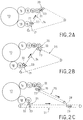
- FIGS. 2A, 2B and 2C show three possible examples of configuration at the output of the card, allowing the parallel production of two fibrous webs, and their superposition.
- the main drum of the card is referenced 13.
- the first upper outlet channel consists of a counter-drum 14, a doffer 15, and two successive condensers 16 and 17; the second lower outlet channel is constituted by a counter-drum 18 and a comber 19.
- These two outlet channels are respectively equipped with a device 20, 21, which is similar to that of FIG. 1.
- the detaching cylinder and the suction box of each device are respectively referenced 22 and 23; the last condenser cylinder 17 for the upper track and the comb cylinder 19 for the lower track correspond to the working cylinder 1 of the device of FIG. 1.
- this belt conveyor comprises a rectilinear portion 24, which is used for the reception of the two fibrous webs at the level of the two devices 20 and 21.
- this rectilinear portion 24 is conveyed by this rectilinear portion 24 to the entrance to the vacuum zone created by the suction box 23 of the device 20 of the upper channel.
- the second fibrous web coming from the upper track is superimposed on the first fibrous web, the suction flow created by the suction box making it possible both to maintain the first fibrous web coming from the lower track to the surface of the rectilinear portion 24 and detach the second fibrous web from the upper track to superimpose it on the first fibrous web.
- the detaching cylinder 22 and the suction box 23 of the device 20 of the upper outlet channel are positioned on either side of the straight portion 25 of the belt conveyor, just downstream the change of direction of the conveyor belt.
- This alternative embodiment has the advantage of avoiding the risks of detachment of the fibrous web during the change of direction of the conveyor. In fact, when the first fibrous web coming from the lower track arrives at this change of direction, it is kept on the surface of the conveyor due to the presence of the suction box 23 just downstream of this change of direction.
- each device 20, 21 has its own conveyor belt 26, 27.
- the detaching cylinder 22 of each device 20, 21 is situated substantially directly above the condenser 17 and the comber 19 respectively.
- the conveyor 25 is horizontal.
- the conveyor 27 is inclined downward and allows the routing of the fibrous web coming from the upper track to the surface and in the extension of the transporter 27. The superposition of the two fibrous webs coming from the card is therefore carried out at the level of the zone. junction 28 between the two conveyors 26 and 27.
- suction means whose function is on the one hand to maintain the first fibrous web from the lower path to the surface of the conveyor 27 during the superposition of the two webs and on the other hand to place, on this conveyor 27, the fibrous web conveyed by the conveyor 26.
Landscapes
- Engineering & Computer Science (AREA)
- Textile Engineering (AREA)
- Preliminary Treatment Of Fibers (AREA)
- Nonwoven Fabrics (AREA)
- Vending Machines For Individual Products (AREA)
- Laminated Bodies (AREA)
- Registering, Tensioning, Guiding Webs, And Rollers Therefor (AREA)
Applications Claiming Priority (2)
| Application Number | Priority Date | Filing Date | Title |
|---|---|---|---|
| FR9411920A FR2725216B1 (fr) | 1994-09-30 | 1994-09-30 | Dispositif pour detacher et transporter a grande vitesse un voile fibreux en sortie de carde |
| FR9411920 | 1994-09-30 |
Publications (3)
| Publication Number | Publication Date |
|---|---|
| EP0704561A1 true EP0704561A1 (de) | 1996-04-03 |
| EP0704561B1 EP0704561B1 (de) | 1998-04-15 |
| EP0704561B2 EP0704561B2 (de) | 2004-07-28 |
Family
ID=9467603
Family Applications (1)
| Application Number | Title | Priority Date | Filing Date |
|---|---|---|---|
| EP94490055A Expired - Lifetime EP0704561B2 (de) | 1994-09-30 | 1994-11-16 | Vorrichtung zur Abnahme und zum Transportieren mit hoher Geschwindigkeit eines Faservlieses am Ende einer Karde |
Country Status (7)
| Country | Link |
|---|---|
| US (1) | US5584101A (de) |
| EP (1) | EP0704561B2 (de) |
| JP (1) | JPH08209461A (de) |
| AT (1) | ATE165125T1 (de) |
| DE (2) | DE704561T1 (de) |
| DK (1) | DK0704561T4 (de) |
| FR (1) | FR2725216B1 (de) |
Cited By (7)
| Publication number | Priority date | Publication date | Assignee | Title |
|---|---|---|---|---|
| WO1998004765A1 (de) * | 1996-07-30 | 1998-02-05 | Maschinenfabrik Rieter Ag | Fasersortiereinrichtung |
| EP0950733A1 (de) * | 1998-04-17 | 1999-10-20 | Thibeau | Verfahren und Einrichtung zum Formen eines luftgelegten Faservlieses |
| EP0962561A1 (de) * | 1998-06-05 | 1999-12-08 | FONDERIE OFFICINE RIUNITE F.O.R. ING. GRAZIANO DI L. GRAZIANO & C. S.a.s. | Kardiermaschine mit einer Abnehmerwalze |
| EP1589132A1 (de) * | 2004-04-22 | 2005-10-26 | Thibeau | Karde mit einer drehbaren Absaugübertragungsvorrichtung |
| EP1672110A1 (de) | 2004-12-16 | 2006-06-21 | Asselin-Thibeau | Verfahren und Vorrichtung zum Transport eines Krempelvlies oder eines Vliesgewebe nach dem Airlaidverfahren |
| EP0817875B2 (de) † | 1995-03-31 | 2006-08-16 | Spinnbau GmbH | Vorrichtung und gerät für die herstellung von vliesen |
| US9522111B2 (en) | 2011-12-16 | 2016-12-20 | Colgate-Palmolive Company | Color changing compositions |
Families Citing this family (17)
| Publication number | Priority date | Publication date | Assignee | Title |
|---|---|---|---|---|
| US5989688A (en) * | 1995-10-11 | 1999-11-23 | Jacob Holm Industries (France) Sas | Composite nonwovens and methods for the preparation thereof |
| US6195842B1 (en) * | 1995-12-08 | 2001-03-06 | E. I. Du Pont De Nemours And Company | Feeding carded fiber to an airlay |
| US6061876A (en) * | 1997-06-11 | 2000-05-16 | John D. Hollingsworth On Wheels, Inc. | Textile recycling machine |
| US5930871A (en) * | 1998-07-09 | 1999-08-03 | John D. Hollingsworth On Wheels, Inc. | Air doffing system for a textile processing machine |
| DE19837182B4 (de) * | 1998-08-17 | 2007-01-25 | Stahlecker, Fritz | Transportband zum Transportieren eines zu verdichtenden Faserverbandes |
| EP1295973B1 (de) * | 2001-09-25 | 2005-12-07 | Spinnbau GmbH | Anlage und Verfahren zum Transportieren von textilen Flächengebilden |
| FR2830263B1 (fr) * | 2001-10-03 | 2004-08-06 | Thibeau | Procede et installation pour la production d'un non-tisse condense, et dispositif de condensation d'un non-tisse |
| DE10234803A1 (de) * | 2002-07-31 | 2004-02-12 | Erko Textilmaschinen Gmbh | Vorrichtung zur Abnahme eines Faservlieses von einer Karde, mit einer Absaugwalze |
| FR2853331B1 (fr) * | 2003-04-01 | 2005-06-24 | Thibeau | Machine pour la fabrication d'un non-tisse par voie aeraulique, comportant des moyens pour une aspiration degressive |
| DE50308225D1 (de) * | 2003-07-29 | 2007-10-31 | Spinnbau Gmbh | Vlieskrempel und Verfahren zur Herstellung eines Faservlieses |
| US7111366B2 (en) * | 2004-08-05 | 2006-09-26 | Akiva Pinto | Machine for making a non-woven fibrous web |
| ITTO20040115U1 (it) * | 2004-09-24 | 2004-12-24 | Fincarde S P A | Sistema per il trasferimento di un velo di fibre proveniente da una carda. |
| DE102015014301A1 (de) | 2015-11-06 | 2017-05-11 | Hubert Hergeth | Saugsammelband |
| DE102017118111A1 (de) * | 2017-08-09 | 2019-02-14 | TRüTZSCHLER GMBH & CO. KG | Karde |
| ES2953571T3 (es) * | 2019-01-08 | 2023-11-14 | Andritz Perfojet Sas | Instalación y procedimiento de producción de telas no tejidas |
| CN110373751A (zh) * | 2019-07-03 | 2019-10-25 | 东华大学 | 一种均匀贴合棉网传动装置 |
| CN110923945A (zh) * | 2019-07-26 | 2020-03-27 | 浙江兴弘包装材料有限公司 | 一种新型pet热封无纺布成套加工设备及加工工艺 |
Citations (5)
| Publication number | Priority date | Publication date | Assignee | Title |
|---|---|---|---|---|
| GB962162A (en) * | 1960-08-03 | 1964-07-01 | Birfield Eng Ltd | Improvements in or relating to carding engines |
| US3787930A (en) * | 1971-08-12 | 1974-01-29 | Kendall & Co | Process for randomizing card webs |
| AT381960B (de) * | 1983-05-05 | 1986-12-29 | Fehrer Ernst | Vorrichtung zum herstellen von faservliesen |
| EP0282996A2 (de) * | 1987-03-19 | 1988-09-21 | Japan Cotton Technical And Economic Research Institute Mengyokaikan | Vorrichtung zur Beseitigung von kurzen Fasern |
| EP0484812A1 (de) * | 1990-11-06 | 1992-05-13 | FA-MA JERSEY S.p.A. | Vorrichtung für die Bildung eines mehrschichtigen Vlieses aus zufallsorientierten Fasern sowie ein mit dieser Vorrichtung angefertigtes Vlies |
Family Cites Families (12)
| Publication number | Priority date | Publication date | Assignee | Title |
|---|---|---|---|---|
| GB880698A (en) † | 1958-12-03 | 1961-10-25 | Tmm Research Ltd | Improvements in apparatus for use in processing textile fibres |
| DE1510449A1 (de) * | 1965-11-26 | 1971-03-18 | Tessiltecnica Di M Mealli | Abnahmevorrichtung fuer eine Textilfaserbahn,insbesondere gekrempelter,garnettierter oder wiederaufbereiteter Fasern |
| AT324894B (de) † | 1973-07-30 | 1975-09-25 | Fehrer Ernst | Vorrichtung zum herstellen von faservliesen |
| US4274178A (en) * | 1979-03-28 | 1981-06-23 | Kabushiki Kaisha Kyowa Kikai Seisakusho | Device for stripping a fibrous web from a doffer in a carding machine |
| US4475272A (en) * | 1983-02-07 | 1984-10-09 | Rando Machine Company | Sliver forming condenser |
| DD226600A1 (de) † | 1984-08-30 | 1985-08-28 | Westthueringer Kammgarnspinner | Vorrichtung zur abnahme eines krempelvlieses vom abnehmer einer krempel |
| DE3722771C1 (de) * | 1987-07-09 | 1989-02-02 | Hollingsworth Gmbh | Vorrichtung zum Zusammenfuehren eines textilen Faservlieses zu einem Faserband |
| DE3901313A1 (de) * | 1989-01-18 | 1990-07-19 | Hollingsworth Gmbh | Vlieskrempel |
| IT1248587B (it) * | 1991-06-28 | 1995-01-19 | Nicola Napolitano | Macchina cardatrice a tamburi,in particolare per la preparazione di tessuti non tessuti e nastri in fibre naturali od artificiali. |
| EP0521444B2 (de) * | 1991-07-02 | 2001-01-24 | Japan Vilene Company, Ltd. | Verfahren und Anlage zur Herstellung einer Faserbahn |
| AT396791B (de) * | 1992-06-26 | 1993-11-25 | Fehrer Ernst | Vorrichtung zum herstellen eines vlieses |
| AT400582B (de) * | 1993-06-18 | 1996-01-25 | Fehrer Ernst | Vorrichtung zum herstellen eines faservlieses |
-
1994
- 1994-09-30 FR FR9411920A patent/FR2725216B1/fr not_active Expired - Lifetime
- 1994-11-16 EP EP94490055A patent/EP0704561B2/de not_active Expired - Lifetime
- 1994-11-16 DK DK94490055T patent/DK0704561T4/da active
- 1994-11-16 AT AT94490055T patent/ATE165125T1/de active
- 1994-11-16 DE DE0704561T patent/DE704561T1/de active Pending
- 1994-11-16 DE DE69409648T patent/DE69409648T3/de not_active Expired - Lifetime
-
1995
- 1995-09-22 US US08/532,973 patent/US5584101A/en not_active Expired - Lifetime
- 1995-09-29 JP JP7276453A patent/JPH08209461A/ja active Pending
Patent Citations (5)
| Publication number | Priority date | Publication date | Assignee | Title |
|---|---|---|---|---|
| GB962162A (en) * | 1960-08-03 | 1964-07-01 | Birfield Eng Ltd | Improvements in or relating to carding engines |
| US3787930A (en) * | 1971-08-12 | 1974-01-29 | Kendall & Co | Process for randomizing card webs |
| AT381960B (de) * | 1983-05-05 | 1986-12-29 | Fehrer Ernst | Vorrichtung zum herstellen von faservliesen |
| EP0282996A2 (de) * | 1987-03-19 | 1988-09-21 | Japan Cotton Technical And Economic Research Institute Mengyokaikan | Vorrichtung zur Beseitigung von kurzen Fasern |
| EP0484812A1 (de) * | 1990-11-06 | 1992-05-13 | FA-MA JERSEY S.p.A. | Vorrichtung für die Bildung eines mehrschichtigen Vlieses aus zufallsorientierten Fasern sowie ein mit dieser Vorrichtung angefertigtes Vlies |
Cited By (9)
| Publication number | Priority date | Publication date | Assignee | Title |
|---|---|---|---|---|
| EP0817875B2 (de) † | 1995-03-31 | 2006-08-16 | Spinnbau GmbH | Vorrichtung und gerät für die herstellung von vliesen |
| WO1998004765A1 (de) * | 1996-07-30 | 1998-02-05 | Maschinenfabrik Rieter Ag | Fasersortiereinrichtung |
| EP0950733A1 (de) * | 1998-04-17 | 1999-10-20 | Thibeau | Verfahren und Einrichtung zum Formen eines luftgelegten Faservlieses |
| FR2777575A1 (fr) * | 1998-04-17 | 1999-10-22 | Thibeau | Procede et installation pour la formation d'un voile fibreux par voie aeraulique |
| US6195845B1 (en) | 1998-04-17 | 2001-03-06 | Thibeau | Method and an installation for forming a fiber web by the airlay technique |
| EP0962561A1 (de) * | 1998-06-05 | 1999-12-08 | FONDERIE OFFICINE RIUNITE F.O.R. ING. GRAZIANO DI L. GRAZIANO & C. S.a.s. | Kardiermaschine mit einer Abnehmerwalze |
| EP1589132A1 (de) * | 2004-04-22 | 2005-10-26 | Thibeau | Karde mit einer drehbaren Absaugübertragungsvorrichtung |
| EP1672110A1 (de) | 2004-12-16 | 2006-06-21 | Asselin-Thibeau | Verfahren und Vorrichtung zum Transport eines Krempelvlies oder eines Vliesgewebe nach dem Airlaidverfahren |
| US9522111B2 (en) | 2011-12-16 | 2016-12-20 | Colgate-Palmolive Company | Color changing compositions |
Also Published As
| Publication number | Publication date |
|---|---|
| DE69409648T3 (de) | 2005-02-17 |
| US5584101A (en) | 1996-12-17 |
| EP0704561B2 (de) | 2004-07-28 |
| DE69409648T2 (de) | 1998-08-20 |
| DE704561T1 (de) | 1997-06-05 |
| ATE165125T1 (de) | 1998-05-15 |
| DK0704561T3 (da) | 1998-06-02 |
| FR2725216A1 (fr) | 1996-04-05 |
| DE69409648D1 (de) | 1998-05-20 |
| DK0704561T4 (da) | 2004-09-06 |
| JPH08209461A (ja) | 1996-08-13 |
| FR2725216B1 (fr) | 1996-12-20 |
| EP0704561B1 (de) | 1998-04-15 |
Similar Documents
| Publication | Publication Date | Title |
|---|---|---|
| EP0704561B1 (de) | Vorrichtung zur Abnahme und zum Transportieren mit hoher Geschwindigkeit eines Faservlieses am Ende einer Karde | |
| EP0733729B1 (de) | Saugzylinder, der die Übergabe von Faservlies zwischen einem Transportband und zwei Kalanderwalzen ermöglicht | |
| EP0085017B1 (de) | Vorrichtung zum Strecken, Verdichten und Zuführen einer Faserlunte während eines Spinnvorganges | |
| EP2964825B1 (de) | Verfahren und vorrichtung zum ausbreiten eines gewebeartigen textilstoffs | |
| EP1163383B1 (de) | Vliesleger | |
| EP2365113B1 (de) | Eingangs wagen eines Vlieslegers mit strukturierter rolle | |
| EP3545122B1 (de) | Vorrichtung zum strecken einer bahn zwischen einer kardiervorrichtung und einem kreuzleger | |
| EP1300492B1 (de) | Verfahren und Anlage zur Herstellung eines verdichteten Vliesstoffes und Vorrichtung zur Verdichtung eines Vliesstoffes | |
| EP2957673B1 (de) | Trocknungsverfahren einer zigarettenpapierbahn, und so erhaltenes zigarettenpapier | |
| EP1589132B1 (de) | Karde mit einer drehbaren Absaugübertragungsvorrichtung | |
| BE1006222A3 (fr) | Dispositif de fabrication d'un feutre de fibres. | |
| EP2128314B1 (de) | Puffervorrichtung und -system sowie Produktionssystem einer Vliesstoffbahn | |
| EP1798175B1 (de) | Förderung einer vliesstoffbahn mittels einer förderbahn mit aufsteigendem förderteil und/oder veränderlicher geschwindigkeit | |
| EP1897979A2 (de) | Verfahren und System zur Produktion eines mehrschichtigen Vlieses, insbesondere mittels eines Vlieslegers | |
| EP1777182B1 (de) | Verfahren und Vorrichtung zum Transport einer Bahn von Vliesstoff mit elektrostatischer Halterung der Bahn von Vliesstoff | |
| EP2041509A2 (de) | Trommelvorrichtung und flexible gurte | |
| EP1702874B1 (de) | Method and device of transporting a non-woven web with electrostatic charge in at least an area with a dimension smaller than the width of said web | |
| FR2629477A1 (fr) | Procede et dispositif d'etirage d'une nappe pour diminuer sa densite lineaire | |
| EP1777187B1 (de) | Verfahren und Anordnung zur Bildung einer Bahn aus mehrschichtigem Vliesstoff mit elektrostatischem Halten dieser Bahn aus Vliesstoff | |
| FR2586171A1 (fr) | Machine et procede de fabrication de cigarettes | |
| FR3063741A1 (fr) | Etaleur nappeur | |
| FR2566004A1 (fr) | Procede et dispositif de filature pour transporter mecaniquement des fibres separees et les projeter successivement dans une zone de torsion |
Legal Events
| Date | Code | Title | Description |
|---|---|---|---|
| PUAI | Public reference made under article 153(3) epc to a published international application that has entered the european phase |
Free format text: ORIGINAL CODE: 0009012 |
|
| AK | Designated contracting states |
Kind code of ref document: A1 Designated state(s): AT BE CH DE DK GB IT LI |
|
| AX | Request for extension of the european patent |
Free format text: LT;SI |
|
| RAX | Requested extension states of the european patent have changed |
Free format text: LT;SI |
|
| RBV | Designated contracting states (corrected) |
Designated state(s): AT BE CH DE DK GB IT LI |
|
| RAP1 | Party data changed (applicant data changed or rights of an application transferred) |
Owner name: THIBEAU SA |
|
| 17P | Request for examination filed |
Effective date: 19961002 |
|
| 17Q | First examination report despatched |
Effective date: 19970114 |
|
| DET | De: translation of patent claims | ||
| GRAG | Despatch of communication of intention to grant |
Free format text: ORIGINAL CODE: EPIDOS AGRA |
|
| GRAG | Despatch of communication of intention to grant |
Free format text: ORIGINAL CODE: EPIDOS AGRA |
|
| GRAH | Despatch of communication of intention to grant a patent |
Free format text: ORIGINAL CODE: EPIDOS IGRA |
|
| RAP1 | Party data changed (applicant data changed or rights of an application transferred) |
Owner name: THIBEAU |
|
| GRAH | Despatch of communication of intention to grant a patent |
Free format text: ORIGINAL CODE: EPIDOS IGRA |
|
| GRAA | (expected) grant |
Free format text: ORIGINAL CODE: 0009210 |
|
| AK | Designated contracting states |
Kind code of ref document: B1 Designated state(s): AT BE CH DE DK GB IT LI |
|
| REF | Corresponds to: |
Ref document number: 165125 Country of ref document: AT Date of ref document: 19980515 Kind code of ref document: T |
|
| REG | Reference to a national code |
Ref country code: CH Ref legal event code: NV Representative=s name: BOVARD AG PATENTANWAELTE Ref country code: CH Ref legal event code: EP |
|
| ITF | It: translation for a ep patent filed | ||
| GBT | Gb: translation of ep patent filed (gb section 77(6)(a)/1977) |
Effective date: 19980415 |
|
| REF | Corresponds to: |
Ref document number: 69409648 Country of ref document: DE Date of ref document: 19980520 |
|
| REG | Reference to a national code |
Ref country code: DK Ref legal event code: T3 |
|
| PLBQ | Unpublished change to opponent data |
Free format text: ORIGINAL CODE: EPIDOS OPPO |
|
| PLBI | Opposition filed |
Free format text: ORIGINAL CODE: 0009260 |
|
| PLBF | Reply of patent proprietor to notice(s) of opposition |
Free format text: ORIGINAL CODE: EPIDOS OBSO |
|
| 26 | Opposition filed |
Opponent name: SPINNBAU GMBH Effective date: 19990115 |
|
| PLBF | Reply of patent proprietor to notice(s) of opposition |
Free format text: ORIGINAL CODE: EPIDOS OBSO |
|
| PLBF | Reply of patent proprietor to notice(s) of opposition |
Free format text: ORIGINAL CODE: EPIDOS OBSO |
|
| PLAW | Interlocutory decision in opposition |
Free format text: ORIGINAL CODE: EPIDOS IDOP |
|
| APAC | Appeal dossier modified |
Free format text: ORIGINAL CODE: EPIDOS NOAPO |
|
| APAE | Appeal reference modified |
Free format text: ORIGINAL CODE: EPIDOS REFNO |
|
| APAC | Appeal dossier modified |
Free format text: ORIGINAL CODE: EPIDOS NOAPO |
|
| REG | Reference to a national code |
Ref country code: GB Ref legal event code: IF02 |
|
| APBU | Appeal procedure closed |
Free format text: ORIGINAL CODE: EPIDOSNNOA9O |
|
| PUAH | Patent maintained in amended form |
Free format text: ORIGINAL CODE: 0009272 |
|
| STAA | Information on the status of an ep patent application or granted ep patent |
Free format text: STATUS: PATENT MAINTAINED AS AMENDED |
|
| 27A | Patent maintained in amended form |
Effective date: 20040728 |
|
| AK | Designated contracting states |
Kind code of ref document: B2 Designated state(s): AT BE CH DE DK GB IT LI |
|
| GBTA | Gb: translation of amended ep patent filed (gb section 77(6)(b)/1977) |
Effective date: 20040728 |
|
| REG | Reference to a national code |
Ref country code: CH Ref legal event code: AEN Free format text: MAINTIEN DU BREVET DONT L'ETENDUE A ETE MODIFIEE |
|
| REG | Reference to a national code |
Ref country code: DK Ref legal event code: T4 |
|
| APAH | Appeal reference modified |
Free format text: ORIGINAL CODE: EPIDOSCREFNO |
|
| PGFP | Annual fee paid to national office [announced via postgrant information from national office to epo] |
Ref country code: DK Payment date: 20081020 Year of fee payment: 15 |
|
| PGFP | Annual fee paid to national office [announced via postgrant information from national office to epo] |
Ref country code: GB Payment date: 20081107 Year of fee payment: 15 |
|
| PLAB | Opposition data, opponent's data or that of the opponent's representative modified |
Free format text: ORIGINAL CODE: 0009299OPPO |
|
| R26 | Opposition filed (corrected) |
Opponent name: SPINNBAU GMBH Effective date: 19990115 |
|
| REG | Reference to a national code |
Ref country code: DK Ref legal event code: EBP |
|
| GBPC | Gb: european patent ceased through non-payment of renewal fee |
Effective date: 20091116 |
|
| PG25 | Lapsed in a contracting state [announced via postgrant information from national office to epo] |
Ref country code: GB Free format text: LAPSE BECAUSE OF NON-PAYMENT OF DUE FEES Effective date: 20091116 |
|
| PG25 | Lapsed in a contracting state [announced via postgrant information from national office to epo] |
Ref country code: DK Free format text: LAPSE BECAUSE OF NON-PAYMENT OF DUE FEES Effective date: 20091130 |
|
| REG | Reference to a national code |
Ref country code: CH Ref legal event code: PFA Owner name: THIBEAU Free format text: THIBEAU#191, RUE DES CINQ VOIES#59200 TOURCOING (FR) -TRANSFER TO- THIBEAU#191, RUE DES CINQ VOIES#59200 TOURCOING (FR) |
|
| PGFP | Annual fee paid to national office [announced via postgrant information from national office to epo] |
Ref country code: AT Payment date: 20131016 Year of fee payment: 20 Ref country code: CH Payment date: 20131121 Year of fee payment: 20 Ref country code: DE Payment date: 20131121 Year of fee payment: 20 |
|
| PGFP | Annual fee paid to national office [announced via postgrant information from national office to epo] |
Ref country code: IT Payment date: 20131128 Year of fee payment: 20 Ref country code: BE Payment date: 20131121 Year of fee payment: 20 |
|
| REG | Reference to a national code |
Ref country code: DE Ref legal event code: R071 Ref document number: 69409648 Country of ref document: DE |
|
| REG | Reference to a national code |
Ref country code: DE Ref legal event code: R071 Ref document number: 69409648 Country of ref document: DE |
|
| REG | Reference to a national code |
Ref country code: CH Ref legal event code: PL |
|
| REG | Reference to a national code |
Ref country code: AT Ref legal event code: MK07 Ref document number: 165125 Country of ref document: AT Kind code of ref document: T Effective date: 20141116 |