EP0704577A1 - Quick-coupling for connecting implements to an excavator - Google Patents
Quick-coupling for connecting implements to an excavator Download PDFInfo
- Publication number
- EP0704577A1 EP0704577A1 EP95401790A EP95401790A EP0704577A1 EP 0704577 A1 EP0704577 A1 EP 0704577A1 EP 95401790 A EP95401790 A EP 95401790A EP 95401790 A EP95401790 A EP 95401790A EP 0704577 A1 EP0704577 A1 EP 0704577A1
- Authority
- EP
- European Patent Office
- Prior art keywords
- tool
- stops
- shaft
- stop
- arm
- Prior art date
- Legal status (The legal status is an assumption and is not a legal conclusion. Google has not performed a legal analysis and makes no representation as to the accuracy of the status listed.)
- Granted
Links
- 238000010168 coupling process Methods 0.000 title abstract 2
- 238000005859 coupling reaction Methods 0.000 title abstract 2
- 230000008878 coupling Effects 0.000 abstract 1
- 238000004513 sizing Methods 0.000 description 2
- 230000006378 damage Effects 0.000 description 1
- 230000000694 effects Effects 0.000 description 1
- 230000035515 penetration Effects 0.000 description 1
Images


Classifications
-
- E—FIXED CONSTRUCTIONS
- E02—HYDRAULIC ENGINEERING; FOUNDATIONS; SOIL SHIFTING
- E02F—DREDGING; SOIL-SHIFTING
- E02F3/00—Dredgers; Soil-shifting machines
- E02F3/04—Dredgers; Soil-shifting machines mechanically-driven
- E02F3/28—Dredgers; Soil-shifting machines mechanically-driven with digging tools mounted on a dipper- or bucket-arm, i.e. there is either one arm or a pair of arms, e.g. dippers, buckets
- E02F3/36—Component parts
- E02F3/3604—Devices to connect tools to arms, booms or the like
- E02F3/3609—Devices to connect tools to arms, booms or the like of the quick acting type, e.g. controlled from the operator seat
- E02F3/3613—Devices to connect tools to arms, booms or the like of the quick acting type, e.g. controlled from the operator seat with means for absorbing any play therebetween
-
- E—FIXED CONSTRUCTIONS
- E02—HYDRAULIC ENGINEERING; FOUNDATIONS; SOIL SHIFTING
- E02F—DREDGING; SOIL-SHIFTING
- E02F3/00—Dredgers; Soil-shifting machines
- E02F3/04—Dredgers; Soil-shifting machines mechanically-driven
- E02F3/28—Dredgers; Soil-shifting machines mechanically-driven with digging tools mounted on a dipper- or bucket-arm, i.e. there is either one arm or a pair of arms, e.g. dippers, buckets
- E02F3/36—Component parts
- E02F3/3604—Devices to connect tools to arms, booms or the like
- E02F3/3609—Devices to connect tools to arms, booms or the like of the quick acting type, e.g. controlled from the operator seat
- E02F3/364—Devices to connect tools to arms, booms or the like of the quick acting type, e.g. controlled from the operator seat using wedges
Definitions
- the present invention relates to improvements to the devices for attaching a tool to the end of the arm of a hydraulic shovel or the like.
- a quick coupler has two parts, a first part, or attachment member, which is carried by the end of the arm and a second part which is made integral with the tool.
- the second part is mainly constituted by a shaft, or by two pins, fixed relative to the tool.
- the first part which is articulated at the end of the arm, has, in its simplest form, a hook forming a semi-cylindrical cradle capable of being engaged on the shaft of the tool when the latter rests on the ground.
- the present invention which overcomes this drawback, is remarkable in that the fastening member has a stop capable of cooperating, when the tool is locked, with a stop carried by the tool so as to oppose what the tool shaft tends to come out of its cradle.
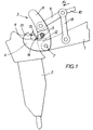
- 1 is the end of the usual arm of a loader on which a tool 2 should be fixed.
- the tool 2 is a hammer -prickler, that is to say a tool which is subjected to alternating forces.
- the hooking member 3 is produced by means of two identical hooks 4, forming cradles, joined by, at least, a cross member 5. Each hook is located on the small branch of a shaped part 6 d'L.
- the attachment member 3 is articulated at the end of the arm 1 by means of a shaft 7 and can pivot around the axis of said shaft by means of links 8 and 9 subjected to the action of 'A cylinder whose piston rod appears at 10 in the drawings.
- the tool 2 has a shaft capable of being grasped by the cradle formed by the hooks 4.
- the aforementioned shaft can be limited to two lateral pins 11.
- Figure 1 shows the tool hung under the arm 1.
- the rod 10 By moving the rod 10 according to the arrow F1 is rotated the fastening member 3 in the same direction until the latter automatically locks at the top of the tool (position shown in Figure 2).
- the means for achieving this locking have not been shown but are described in the aforementioned European patent No. 438931.
- the attachment member has a stop 12 capable of cooperating, when the tool is locked, with a stop 13 provided on the tool.
- the stop 12 has a concave contact surface 14 and the stop 13 has a convex contact surface 15, the stop 12 being fixed relative to the member 3 and that 13 being fixed relative to the tool 2.
- the two surfaces 14 and 15 move on a fictitious cylinder whose axis is coincident with that of the journals 11. In all rigor and for mechanical reasons, the surfaces 14 and 15 evolve on two distinct fictitious cylinders, the difference in radii between the two cylinders resulting from the necessary mechanical play between the two surfaces. It is desirable that this play be as reduced as possible.
- the stop 12 pivots in the same direction and is positioned, at the end of the locking, above the stop 13. In this last position, the forces to which the tool (those acting along arrow F2) are transmitted to the latching member by the stop 13 which cooperates with that 12 and not by the pins 11. The forces exerted in the opposite direction are collected by the semi-cylindrical cradle formed by the hooks 4.
- the stops 12 and 13 are located in planes separate from those containing the hooks.
- the stop 13 is disposed between the pins 11 and that 12 is made integral with the crosspiece 5.
- the contact between the two stops extends over an arc length of less than 180 °, nothing prevents this contact from extending over a length arc close to 180 ° by judicious sizing of the quick coupler, sizing which is within the reach of those skilled in the art.
- the present invention overcomes this drawback, as will emerge from the description below given with reference to FIGS. 3 and 4.
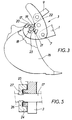
- Figure 3 shows the attachment of a bucket 16 using a hooking member 3.
- the bucket 16 has a shaft 17, fixed relative to said bucket.
- the shaft 17 has two stops 18 and 19, diametrically opposite, capable of cooperating, when the bucket is locked, with two stops 20 and 21 carried by the fastening member 3.
- the stops have contact surfaces 22 and 23 similar to those 14 and 15.
- stops 20 and 21 are arranged towards the outside with respect to the axis of the shaft 17, but this arrangement can be reversed as shown in FIG. 5.
- the shaft 17 has two stops 24 and 25 capable, when the tool is locked, of cooperating with two stops 26 and 27 carried by the member 3.
Landscapes
- Engineering & Computer Science (AREA)
- Mechanical Engineering (AREA)
- Mining & Mineral Resources (AREA)
- Civil Engineering (AREA)
- General Engineering & Computer Science (AREA)
- Structural Engineering (AREA)
- Shovels (AREA)
- Earth Drilling (AREA)
- Load-Engaging Elements For Cranes (AREA)
- Forklifts And Lifting Vehicles (AREA)
Abstract
Description
La présente invention est relative à des perfectionnements aux dispositifs pour fixer un outil à l'extrémité du bras d'une pelle hydraulique ou analogue.The present invention relates to improvements to the devices for attaching a tool to the end of the arm of a hydraulic shovel or the like.
Actuellement, la fixation d'un outil, tel qu'un godet ou un marteau-piqueur, s'effectue par l'entremise d'un dispositif dénommé "attache rapide". Un tel dispositif permet de fixer automatiquement l'outil sans que le conducteur de l'engin quitte sa cabine de commande.Currently, the attachment of a tool, such as a bucket or a jackhammer, is carried out by means of a device called "quick coupler". Such a device enables the tool to be fixed automatically without the operator of the machine leaving his control cabin.
D'une façon générale, une attache rapide comporte deux parties, une première partie, ou organe d'accrochage, qui est portée par l'extrémité du bras et une seconde partie qui est rendue solidaire de l'outil.Generally, a quick coupler has two parts, a first part, or attachment member, which is carried by the end of the arm and a second part which is made integral with the tool.
La seconde partie est principalement constituée par un arbre, ou par deux tourillons, fixe par rapport à l'outil. La première partie, qui est articulée à l'extrémité du bras, présente, dans sa forme la plus simple, un crochet formant un berceau semi-cylindrique susceptible d'être engagé sur l'arbre de l'outil lorsque ce dernier repose sur le sol. Par des rotations judicieuses tant du bras de l'engin que de l'organe d'accrochage par rapport audit bras, il est ensuite possible de verrouiller automatiquement l'outil par rapport audit bras. Les manoeuvres à effectuer pour assurer le verrouillage dépendent des moyens mis en oeuvre pour réaliser l'attache rapide.The second part is mainly constituted by a shaft, or by two pins, fixed relative to the tool. The first part, which is articulated at the end of the arm, has, in its simplest form, a hook forming a semi-cylindrical cradle capable of being engaged on the shaft of the tool when the latter rests on the ground. By judicious rotations of both the arm of the machine and the attachment member with respect to said arm, it is then possible to automatically lock the tool with respect to said arm. The maneuvers to be carried out to ensure locking depend on the means used to make the quick coupler.
Il ressort des explications ci-dessus que le contact de l'arbre de l'outil avec l'organe d'accrochage s'effectue, en fait, par l'entremise d'un palier ouvert. Cette disposition ne pose pas de problème si les efforts auxquels est soumis l'outil durant le travail tendent à plaquer l'arbre dans le palier.It emerges from the above explanations that the contact of the tool shaft with the latching member takes place, in fact, by means of an open bearing. This arrangement is not a problem if the forces to which the tool is subjected during work tend to press the shaft into the bearing.
L'expérience a montré toutefois que pour certains outils, tels que des marteaux-piqueurs, l'effort maximal a une direction telle que seule une partie de la surface du berceau est en contact avec l'arbre de l'outil. Lorsque les efforts sont alternés il se produit un phénomène de matage entre les surfaces en contact et les jeux qui en résultent détruisent rapidement l'attache rapide.Experience has shown, however, that for certain tools, such as jackhammers, the maximum force has a direction such that only part of the surface of the cradle is in contact with the shaft of the tool. When the efforts are alternated, a matting phenomenon occurs between the contacting surfaces and the resulting clearances quickly destroy the quick coupler.
La présente invention, qui remédie à cet inconvénient, est remarquable en ce que l'organe d'accrochage présente une butée susceptible de coopérer, lorsque l'outil est verrouillé, avec une butée portée par l'outil de façon à s'opposer à ce que l'arbre de l'outil tende à sortir de son berceau.The present invention, which overcomes this drawback, is remarkable in that the fastening member has a stop capable of cooperating, when the tool is locked, with a stop carried by the tool so as to oppose what the tool shaft tends to come out of its cradle.
La présente invention sera mieux comprise par la description qui va suivre faite en se référant aux dessins annexés, à titre d'exemple indicatif seulement, sur lesquels :
- la figure 1 est une vue partielle, en élévation, montrant l'accrochage d'un outil à l'extrémité du bras d'un chargeur à l'aide d'une attache rapide comportant le dispositif de l'invention;
- la figure 2 est une vue, analogue à celle 1, montrant l'outil verrouillé;
- la figure 3 est une vue analogue à la figure 1 montrant une variante de réalisation;
- la figure 4 est une vue analogue à la figure 3 montrant l'outil en position verrouillée;
- la figure 5 est une vue en coupe effectuée selon la ligne V-V de la figure 4 montrant une variante de réalisation, cette vue est partielle et effectuée à plus grande échelle.
- Figure 1 is a partial view, in elevation, showing the attachment of a tool at the end of the arm of a loader using a quick coupler comprising the device of the invention;
- Figure 2 is a view, similar to that 1, showing the locked tool;
- Figure 3 is a view similar to Figure 1 showing an alternative embodiment;
- Figure 4 is a view similar to Figure 3 showing the tool in the locked position;
- Figure 5 is a sectional view taken along the line VV of Figure 4 showing an alternative embodiment, this view is partial and made on a larger scale.
Dans la description qui va suivre, il y a lieu de noter que l'invention est appliquée à une attache rapide du genre de celle décrite dans le brevet européen N°438931. De ce fait, les caractéristiques qui ne sont pas utiles à la compréhension de la présente invention n'ont pas été décrites ni représentées.In the description which follows, it should be noted that the invention is applied to a quick coupler of the kind described in European patent No. 438931. Therefore, the characteristics which are not useful for understanding the present invention have not been described or shown.
En se reportant aux dessins et selon un mode de réalisation, on voit que 1 est l'extrémité du bras usuel d'un chargeur sur laquelle il convient de fixer un outil 2. Dans l'exemple représenté, l'outil 2 est un marteau-piqueur, c'est-à-dire un outil qui est soumis à des efforts alternés.Referring to the drawings and according to one embodiment, it can be seen that 1 is the end of the usual arm of a loader on which a
De la façon connue, l'organe d'accrochage 3 est réalisé au moyen de deux crochets 4 identiques, formant berceaux, réunis par, au moins, une traverse 5. Chaque crochet est situé sur la petite branche d'une pièce 6 en forme d'L.In known manner, the hooking
L'organe d'accrochage 3 est articulé à l'extrémité du bras 1 par l'entremise d'un arbre 7 et peut pivoter autour de l'axe dudit arbre par l'entremise de biellettes 8 et 9 soumises à l'action d'un vérin dont la tige de piston apparaît en 10 sur les dessins.The
De la façon connue, l'outil 2 présente un arbre susceptible d'être saisi par le berceau formé par les crochets 4. L'arbre précité peut être limité à deux tourillons latéraux 11.In known manner, the
La figure 1 montre l'outil accroché sous le bras 1. En déplaçant la tige 10 selon la flèche F₁ on fait pivoter l'organe d'accrochage 3 dans le même sens jusqu'à ce que ce dernier se verrouille automatiquement à la partie supérieure de l'outil (position montrée sur la figure 2). Les moyens permettant de réaliser ce verrouillage n'ont pas été représentés mais sont décrits dans le brevet européen N° 438931 précité.Figure 1 shows the tool hung under the arm 1. By moving the
Si on considère la figure 2, on constate que le contact entre les tourillons 11 et les demi-paliers constitués par les crochets 4 est très réduit et qu'un effort s'exerçant, de façon répétée, selon la flèche F₂, parallèle à l'axe XX₁ de la pointe P de l'outil, aura pour effet de réaliser le matage des surfaces en contact et d'entraîner la destruction de l'attache rapide.If we consider Figure 2, we see that the contact between the
Selon l'invention, l'organe d'accrochage présente une butée 12 susceptible de coopérer, lorsque l'outil est verrouillé, avec une butée 13 prévue sur l'outil.According to the invention, the attachment member has a
La butée 12 présente une surface de contact 14 concave et la butée 13 présente une surface de contact 15 convexe, la butée 12 étant fixe par rapport à l'organe 3 et celle 13 étant fixe par rapport à l'outil 2.The
Les deux surfaces 14 et 15 se déplacent sur un cylindre fictif dont l'axe est confondu avec celui des tourillons 11. En toute rigueur et pour des raisons mécaniques, les surfaces 14 et 15 évoluent sur deux cylindres fictifs distincts, la différence de rayons entre les deux cylindres résultant du jeu mécanique nécessaire entre les deux surfaces. Il est souhaitable que ce jeu soit aussi réduit que possible.The two
Lors de la saisie de l'outil, les deux butées occupent les positions montrées sur la figure 1, il est à noter que, dans cette position, la butée 12 est "escamotée" par rapport au berceau semi-cylindrique formé par les crochets 4 et qu'elle ne peut pas s'opposer à la pénétration des tourillons dans ledit berceau.When entering the tool, the two stops occupy the positions shown in Figure 1, it should be noted that, in this position, the
Lors du pivotement de l'organe d'accrochage 3, la butée 12 pivote dans le même sens et vient se positionner, à la fin du verrouillage, au-dessus de la butée 13. Dans cette dernière position, les efforts auxquels est soumis l'outil (ceux s'exerçant selon la flèche F2) sont transmis à l'organe d'accrochage par la butée 13 qui coopère avec celle 12 et non par les tourillons 11. Les efforts qui s'exercent en sens inverse sont encaissés par le berceau semi-cylindrique formé par les crochets 4.During the pivoting of the fastening
Les butées 12 et 13 sont situées dans des plans distincts de ceux contenant les crochets. De préférence, la butée 13 est disposée entre les tourillons 11 et celle 12 est rendue solidaire de la traverse 5.The
Bien que, dans le mode de réalisation décrit en regard des figures 1 et 2, le contact entre les deux butées s'étende sur une longueur d'arc inférieure à 180°, rien n'empêche que ce contact s'étende sur une longueur d'arc voisine de 180° par un dimensionnement judicieux de l'attache rapide, dimensionnement qui est à la portée de l'homme de l'art.Although, in the embodiment described with reference to FIGS. 1 and 2, the contact between the two stops extends over an arc length of less than 180 °, nothing prevents this contact from extending over a length arc close to 180 ° by judicious sizing of the quick coupler, sizing which is within the reach of those skilled in the art.
Si, dans le cas de l'outil des figures 1 et 2, le contact entre les crochets et les tourillons 11 s'effectue selon une surface qui est suffisamment importante, l'expérience a montré que ce n'était pas le cas pour d'autres outils.If, in the case of the tool of FIGS. 1 and 2, the contact between the hooks and the
La présente invention permet de remédier à cet inconvénient, comme cela va ressortir de la description ci-dessous faite en regard des figures 3 et 4.The present invention overcomes this drawback, as will emerge from the description below given with reference to FIGS. 3 and 4.
Les organes communs aux cinq figures seront affectés des mêmes références.The bodies common to the five figures will be given the same references.
La figure 3 montre l'accrochage d'un godet 16 à l'aide d'un organe d'acccrochage 3. A cet effet, le godet 16 comporte un arbre 17, fixe par rapport audit godet.Figure 3 shows the attachment of a
Selon l'invention, l'arbre 17 présente deux butées 18 et 19, diamétralement opposées, susceptibles de coopérer, lorsque le godet est verrouillé, avec deux butées 20 et 21 portées par l'organe d'accrochage 3.According to the invention, the
Les butées présentent des surfaces de contact 22 et 23 analogues à celles 14 et 15.The stops have
Dans l'exemple des figures 3 et 4, les butées 20 et 21 sont disposées vers l'extérieur par rapport à l'axe de l'arbre 17, mais cette disposition peut être inversée comme cela ressort de la figure 5.In the example of FIGS. 3 and 4, the
En se reportant à la figure 5, on voit que l'arbre 17 présente deux butées 24 et 25 susceptibles, lorsque l'outil est verrouillé, de coopérer avec deux butées 26 et 27 portées par l'organe 3.Referring to FIG. 5, it can be seen that the
Claims (5)
Applications Claiming Priority (4)
| Application Number | Priority Date | Filing Date | Title |
|---|---|---|---|
| FR9411631 | 1994-09-29 | ||
| FR9411631A FR2725223B1 (en) | 1994-09-29 | 1994-09-29 | IMPROVEMENTS ON DEVICES FOR ATTACHING A TOOL AT THE END OF THE ARM OF A HYDRAULIC SHOVEL OR THE LIKE |
| FR9506566A FR2725224B1 (en) | 1994-09-29 | 1995-06-02 | IMPROVEMENTS ON DEVICES FOR ATTACHING A TOOL AT THE END OF THE ARM OF A HYDRAULIC SHOVEL OR THE LIKE |
| FR9506566 | 1995-06-02 |
Publications (2)
| Publication Number | Publication Date |
|---|---|
| EP0704577A1 true EP0704577A1 (en) | 1996-04-03 |
| EP0704577B1 EP0704577B1 (en) | 2000-02-09 |
Family
ID=26231431
Family Applications (1)
| Application Number | Title | Priority Date | Filing Date |
|---|---|---|---|
| EP95401790A Expired - Lifetime EP0704577B1 (en) | 1994-09-29 | 1995-07-28 | Quick-coupling for connecting implements to an excavator |
Country Status (6)
| Country | Link |
|---|---|
| EP (1) | EP0704577B1 (en) |
| AT (1) | ATE189726T1 (en) |
| DE (1) | DE69514973T2 (en) |
| DK (1) | DK0704577T3 (en) |
| ES (1) | ES2144588T3 (en) |
| FR (1) | FR2725224B1 (en) |
Cited By (3)
| Publication number | Priority date | Publication date | Assignee | Title |
|---|---|---|---|---|
| EP0810330A1 (en) * | 1996-05-30 | 1997-12-03 | Societe A Responsabilite Limitee : Morin Freres | Device for connecting a tool to the end of an arm of an excavator |
| FR2760029A1 (en) * | 1997-02-24 | 1998-08-28 | Case France | Attachment for holding excavating buckets or similar tools |
| WO2007059721A1 (en) * | 2005-11-28 | 2007-05-31 | Robert Riedlberger | Centring device for quick-change devices |
Families Citing this family (3)
| Publication number | Priority date | Publication date | Assignee | Title |
|---|---|---|---|---|
| DE102017000852B4 (en) * | 2017-01-31 | 2020-11-05 | Markus Riedlberger | Safety device against unintentional falling out of tools from a quick-change device |
| DE102017130437A1 (en) * | 2017-12-19 | 2019-06-19 | Oilquick Deutschland Gmbh | Quick coupler, adapter and quick-change system |
| DE102017130436A1 (en) * | 2017-12-19 | 2019-06-19 | Oilquick Deutschland Gmbh | Adapter, quick coupler and quick-change system |
Citations (4)
| Publication number | Priority date | Publication date | Assignee | Title |
|---|---|---|---|---|
| FR2162156A1 (en) * | 1971-12-01 | 1973-07-13 | Verachtert Antonius | |
| FR2316387A1 (en) * | 1975-06-21 | 1977-01-28 | Orenstein & Koppel Ag | Coupling for boom accessories to hydraulic dredgers - has two halves held together by hooks engaging pins |
| EP0438931A1 (en) | 1990-01-26 | 1991-07-31 | Societe En Nom Collectif Morin Freres | Device for connecting a bucket, or the like, to the boom end of a loader |
| DE9204711U1 (en) * | 1992-04-05 | 1992-07-16 | Eisenwerke Kaiserslautern Gmbh, 6750 Kaiserslautern | Quick-change device for construction machinery |
-
1995
- 1995-06-02 FR FR9506566A patent/FR2725224B1/en not_active Expired - Fee Related
- 1995-07-28 DK DK95401790T patent/DK0704577T3/en active
- 1995-07-28 AT AT95401790T patent/ATE189726T1/en active
- 1995-07-28 EP EP95401790A patent/EP0704577B1/en not_active Expired - Lifetime
- 1995-07-28 DE DE69514973T patent/DE69514973T2/en not_active Expired - Lifetime
- 1995-07-28 ES ES95401790T patent/ES2144588T3/en not_active Expired - Lifetime
Patent Citations (4)
| Publication number | Priority date | Publication date | Assignee | Title |
|---|---|---|---|---|
| FR2162156A1 (en) * | 1971-12-01 | 1973-07-13 | Verachtert Antonius | |
| FR2316387A1 (en) * | 1975-06-21 | 1977-01-28 | Orenstein & Koppel Ag | Coupling for boom accessories to hydraulic dredgers - has two halves held together by hooks engaging pins |
| EP0438931A1 (en) | 1990-01-26 | 1991-07-31 | Societe En Nom Collectif Morin Freres | Device for connecting a bucket, or the like, to the boom end of a loader |
| DE9204711U1 (en) * | 1992-04-05 | 1992-07-16 | Eisenwerke Kaiserslautern Gmbh, 6750 Kaiserslautern | Quick-change device for construction machinery |
Cited By (5)
| Publication number | Priority date | Publication date | Assignee | Title |
|---|---|---|---|---|
| EP0810330A1 (en) * | 1996-05-30 | 1997-12-03 | Societe A Responsabilite Limitee : Morin Freres | Device for connecting a tool to the end of an arm of an excavator |
| FR2749332A1 (en) * | 1996-05-30 | 1997-12-05 | Morin Freres | DEVICE FOR ATTACHING A TOOL AT THE END OF THE ARM OF A MECHANICAL SHOVEL |
| FR2760029A1 (en) * | 1997-02-24 | 1998-08-28 | Case France | Attachment for holding excavating buckets or similar tools |
| WO2007059721A1 (en) * | 2005-11-28 | 2007-05-31 | Robert Riedlberger | Centring device for quick-change devices |
| US7752781B2 (en) | 2005-11-28 | 2010-07-13 | Robert Riedlberger | Centring device for quick-change devices |
Also Published As
| Publication number | Publication date |
|---|---|
| DE69514973T2 (en) | 2000-07-27 |
| DK0704577T3 (en) | 2000-07-24 |
| FR2725224A1 (en) | 1996-04-05 |
| DE69514973D1 (en) | 2000-03-16 |
| EP0704577B1 (en) | 2000-02-09 |
| ATE189726T1 (en) | 2000-02-15 |
| ES2144588T3 (en) | 2000-06-16 |
| FR2725224B1 (en) | 1997-04-18 |
Similar Documents
| Publication | Publication Date | Title |
|---|---|---|
| EP1129259B1 (en) | Quick fastener for fixing a tool at the end of a loading arm or the like | |
| EP0779951B1 (en) | Remote manoeuvrable snap-hook to make a rope fast | |
| EP0438931B1 (en) | Device for connecting a bucket, or the like, to the boom end of a loader | |
| EP0704577B1 (en) | Quick-coupling for connecting implements to an excavator | |
| FR2743978A1 (en) | MOWER WITH PERFECTIONED REMOVAL | |
| FR2624248A1 (en) | SUSPENSION DEVICE FOR CONNECTING A TOOL TO A MOTOR | |
| US5314292A (en) | Material clamping apparatus | |
| FR2725223A1 (en) | Quick-fit coupling for tool on end of hydraulic manipulator arm | |
| CA3150811C (en) | Secure assembly for coupling a tool to a work arm of an improved functioning public works machine | |
| FR2701047A1 (en) | Universal connection system for securing an accessory, in particular a bucket or bucket, to the articulated arm of a public works machine. | |
| FR2785577A1 (en) | Retractable gear lever for vehicles, consists of abase with primary part of lever fitted to base by means of transverse pivot, with socket, which slides down lever to engage on base, to lock the lever in working position. | |
| EP0490798A2 (en) | Crane, especially for handling | |
| EP1587991B1 (en) | Device for adjusting a tool which is fixed to the end of a digger arm or similar | |
| FR2694316A1 (en) | Loader-excavator-elevator vehicle implement - has arm at free end of shaft and tool mounted on arm | |
| EP0810330B1 (en) | Device for connecting a tool to the end of an arm of an excavator | |
| FR2854909A1 (en) | DEVICE FOR COUPLING A TOOL AT THE END OF THE BOOM OF A MACHINE, SUCH AS A HYDRAULIC SHOVEL | |
| EP0256304B1 (en) | Soil-working machine | |
| CH641864A5 (en) | EARTHWORK MACHINE. | |
| FR2494747A1 (en) | Dredging arm attachment for earthworking machine - comprises ram=actuated telescopic arm pivotally attached to existing jointed arm | |
| FR2491901A3 (en) | Safety lifting hook for use with block and tackle - has pivoted closing link pivoted to part of main hooking body to lock it shut | |
| FR2785951A1 (en) | Quick-fit connector for implement such as bucket on end of manipulator arm has stirrup with aperture and locking plate engaging with hook | |
| FR2713681A1 (en) | Control mechanism for digger bucket ejector blade | |
| EP2010720B1 (en) | Device four coupling a tool with the boom of a machine such as a hydraulic shovel | |
| FR2629114A1 (en) | Vehicle for earth moving works | |
| FR2673422A1 (en) | Device for manipulating a tool, which can be fitted to an agricultural loader |
Legal Events
| Date | Code | Title | Description |
|---|---|---|---|
| PUAI | Public reference made under article 153(3) epc to a published international application that has entered the european phase |
Free format text: ORIGINAL CODE: 0009012 |
|
| 17P | Request for examination filed |
Effective date: 19960116 |
|
| AK | Designated contracting states |
Kind code of ref document: A1 Designated state(s): AT BE CH DE DK ES FR GB IT LI NL SE |
|
| 17Q | First examination report despatched |
Effective date: 19980707 |
|
| GRAG | Despatch of communication of intention to grant |
Free format text: ORIGINAL CODE: EPIDOS AGRA |
|
| GRAG | Despatch of communication of intention to grant |
Free format text: ORIGINAL CODE: EPIDOS AGRA |
|
| GRAH | Despatch of communication of intention to grant a patent |
Free format text: ORIGINAL CODE: EPIDOS IGRA |
|
| GRAH | Despatch of communication of intention to grant a patent |
Free format text: ORIGINAL CODE: EPIDOS IGRA |
|
| GRAA | (expected) grant |
Free format text: ORIGINAL CODE: 0009210 |
|
| AK | Designated contracting states |
Kind code of ref document: B1 Designated state(s): AT BE CH DE DK ES FR GB IT LI NL SE |
|
| REF | Corresponds to: |
Ref document number: 189726 Country of ref document: AT Date of ref document: 20000215 Kind code of ref document: T |
|
| REG | Reference to a national code |
Ref country code: CH Ref legal event code: EP |
|
| REF | Corresponds to: |
Ref document number: 69514973 Country of ref document: DE Date of ref document: 20000316 |
|
| ITF | It: translation for a ep patent filed | ||
| REG | Reference to a national code |
Ref country code: CH Ref legal event code: NV Representative=s name: BOVARD AG PATENTANWAELTE |
|
| REG | Reference to a national code |
Ref country code: ES Ref legal event code: FG2A Ref document number: 2144588 Country of ref document: ES Kind code of ref document: T3 |
|
| EN | Fr: translation not filed | ||
| GBT | Gb: translation of ep patent filed (gb section 77(6)(a)/1977) |
Effective date: 20000616 |
|
| REG | Reference to a national code |
Ref country code: DK Ref legal event code: T3 |
|
| EN4 | Fr: notification of non filing translation in an earlier bopi is erroneous | ||
| PLBE | No opposition filed within time limit |
Free format text: ORIGINAL CODE: 0009261 |
|
| STAA | Information on the status of an ep patent application or granted ep patent |
Free format text: STATUS: NO OPPOSITION FILED WITHIN TIME LIMIT |
|
| 26N | No opposition filed | ||
| REG | Reference to a national code |
Ref country code: GB Ref legal event code: IF02 |
|
| REG | Reference to a national code |
Ref country code: FR Ref legal event code: CL |
|
| REG | Reference to a national code |
Ref country code: CH Ref legal event code: PFA Owner name: SOCIETE A RESPONSABILITE LIMITEE : MORIN FRERES Free format text: SOCIETE A RESPONSABILITE LIMITEE : MORIN FRERES#LIEUDIT "LES BRETECHES"#F-45740 LAILLY EN VAL (FR) -TRANSFER TO- SOCIETE A RESPONSABILITE LIMITEE : MORIN FRERES#LIEUDIT "LES BRETECHES"#F-45740 LAILLY EN VAL (FR) |
|
| PGFP | Annual fee paid to national office [announced via postgrant information from national office to epo] |
Ref country code: DK Payment date: 20110708 Year of fee payment: 17 |
|
| PGFP | Annual fee paid to national office [announced via postgrant information from national office to epo] |
Ref country code: AT Payment date: 20110731 Year of fee payment: 17 Ref country code: SE Payment date: 20110722 Year of fee payment: 17 |
|
| REG | Reference to a national code |
Ref country code: SE Ref legal event code: EUG |
|
| REG | Reference to a national code |
Ref country code: AT Ref legal event code: MM01 Ref document number: 189726 Country of ref document: AT Kind code of ref document: T Effective date: 20120728 |
|
| REG | Reference to a national code |
Ref country code: DK Ref legal event code: EBP |
|
| PG25 | Lapsed in a contracting state [announced via postgrant information from national office to epo] |
Ref country code: SE Free format text: LAPSE BECAUSE OF NON-PAYMENT OF DUE FEES Effective date: 20120729 |
|
| PG25 | Lapsed in a contracting state [announced via postgrant information from national office to epo] |
Ref country code: AT Free format text: LAPSE BECAUSE OF NON-PAYMENT OF DUE FEES Effective date: 20120728 |
|
| PG25 | Lapsed in a contracting state [announced via postgrant information from national office to epo] |
Ref country code: DK Free format text: LAPSE BECAUSE OF NON-PAYMENT OF DUE FEES Effective date: 20120731 |
|
| PGFP | Annual fee paid to national office [announced via postgrant information from national office to epo] |
Ref country code: CH Payment date: 20140715 Year of fee payment: 20 Ref country code: DE Payment date: 20140711 Year of fee payment: 20 Ref country code: NL Payment date: 20140630 Year of fee payment: 20 |
|
| PGFP | Annual fee paid to national office [announced via postgrant information from national office to epo] |
Ref country code: FR Payment date: 20140604 Year of fee payment: 20 Ref country code: GB Payment date: 20140717 Year of fee payment: 20 Ref country code: ES Payment date: 20140725 Year of fee payment: 20 |
|
| PGFP | Annual fee paid to national office [announced via postgrant information from national office to epo] |
Ref country code: IT Payment date: 20140714 Year of fee payment: 20 |
|
| PGFP | Annual fee paid to national office [announced via postgrant information from national office to epo] |
Ref country code: BE Payment date: 20140730 Year of fee payment: 20 |
|
| REG | Reference to a national code |
Ref country code: DE Ref legal event code: R071 Ref document number: 69514973 Country of ref document: DE |
|
| REG | Reference to a national code |
Ref country code: CH Ref legal event code: PL |
|
| REG | Reference to a national code |
Ref country code: GB Ref legal event code: PE20 Expiry date: 20150727 |
|
| PG25 | Lapsed in a contracting state [announced via postgrant information from national office to epo] |
Ref country code: GB Free format text: LAPSE BECAUSE OF EXPIRATION OF PROTECTION Effective date: 20150727 |
|
| REG | Reference to a national code |
Ref country code: ES Ref legal event code: FD2A Effective date: 20151104 |
|
| PG25 | Lapsed in a contracting state [announced via postgrant information from national office to epo] |
Ref country code: ES Free format text: LAPSE BECAUSE OF EXPIRATION OF PROTECTION Effective date: 20150729 |