EP0704577A1 - Schnellkupplung zum Befestigen der Arbeitswerkzeuge an einem Baggerausleger - Google Patents
Schnellkupplung zum Befestigen der Arbeitswerkzeuge an einem Baggerausleger Download PDFInfo
- Publication number
- EP0704577A1 EP0704577A1 EP95401790A EP95401790A EP0704577A1 EP 0704577 A1 EP0704577 A1 EP 0704577A1 EP 95401790 A EP95401790 A EP 95401790A EP 95401790 A EP95401790 A EP 95401790A EP 0704577 A1 EP0704577 A1 EP 0704577A1
- Authority
- EP
- European Patent Office
- Prior art keywords
- tool
- stops
- shaft
- stop
- arm
- Prior art date
- Legal status (The legal status is an assumption and is not a legal conclusion. Google has not performed a legal analysis and makes no representation as to the accuracy of the status listed.)
- Granted
Links
- 238000010168 coupling process Methods 0.000 title abstract 2
- 238000005859 coupling reaction Methods 0.000 title abstract 2
- 230000008878 coupling Effects 0.000 abstract 1
- 238000004513 sizing Methods 0.000 description 2
- 230000006378 damage Effects 0.000 description 1
- 230000000694 effects Effects 0.000 description 1
- 230000035515 penetration Effects 0.000 description 1
Images


Classifications
-
- E—FIXED CONSTRUCTIONS
- E02—HYDRAULIC ENGINEERING; FOUNDATIONS; SOIL SHIFTING
- E02F—DREDGING; SOIL-SHIFTING
- E02F3/00—Dredgers; Soil-shifting machines
- E02F3/04—Dredgers; Soil-shifting machines mechanically-driven
- E02F3/28—Dredgers; Soil-shifting machines mechanically-driven with digging tools mounted on a dipper- or bucket-arm, i.e. there is either one arm or a pair of arms, e.g. dippers, buckets
- E02F3/36—Component parts
- E02F3/3604—Devices to connect tools to arms, booms or the like
- E02F3/3609—Devices to connect tools to arms, booms or the like of the quick acting type, e.g. controlled from the operator seat
- E02F3/3613—Devices to connect tools to arms, booms or the like of the quick acting type, e.g. controlled from the operator seat with means for absorbing any play therebetween
-
- E—FIXED CONSTRUCTIONS
- E02—HYDRAULIC ENGINEERING; FOUNDATIONS; SOIL SHIFTING
- E02F—DREDGING; SOIL-SHIFTING
- E02F3/00—Dredgers; Soil-shifting machines
- E02F3/04—Dredgers; Soil-shifting machines mechanically-driven
- E02F3/28—Dredgers; Soil-shifting machines mechanically-driven with digging tools mounted on a dipper- or bucket-arm, i.e. there is either one arm or a pair of arms, e.g. dippers, buckets
- E02F3/36—Component parts
- E02F3/3604—Devices to connect tools to arms, booms or the like
- E02F3/3609—Devices to connect tools to arms, booms or the like of the quick acting type, e.g. controlled from the operator seat
- E02F3/364—Devices to connect tools to arms, booms or the like of the quick acting type, e.g. controlled from the operator seat using wedges
Definitions
- the present invention relates to improvements to the devices for attaching a tool to the end of the arm of a hydraulic shovel or the like.
- a quick coupler has two parts, a first part, or attachment member, which is carried by the end of the arm and a second part which is made integral with the tool.
- the second part is mainly constituted by a shaft, or by two pins, fixed relative to the tool.
- the first part which is articulated at the end of the arm, has, in its simplest form, a hook forming a semi-cylindrical cradle capable of being engaged on the shaft of the tool when the latter rests on the ground.
- the present invention which overcomes this drawback, is remarkable in that the fastening member has a stop capable of cooperating, when the tool is locked, with a stop carried by the tool so as to oppose what the tool shaft tends to come out of its cradle.
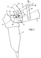
- 1 is the end of the usual arm of a loader on which a tool 2 should be fixed.
- the tool 2 is a hammer -prickler, that is to say a tool which is subjected to alternating forces.
- the hooking member 3 is produced by means of two identical hooks 4, forming cradles, joined by, at least, a cross member 5. Each hook is located on the small branch of a shaped part 6 d'L.
- the attachment member 3 is articulated at the end of the arm 1 by means of a shaft 7 and can pivot around the axis of said shaft by means of links 8 and 9 subjected to the action of 'A cylinder whose piston rod appears at 10 in the drawings.
- the tool 2 has a shaft capable of being grasped by the cradle formed by the hooks 4.
- the aforementioned shaft can be limited to two lateral pins 11.
- Figure 1 shows the tool hung under the arm 1.
- the rod 10 By moving the rod 10 according to the arrow F1 is rotated the fastening member 3 in the same direction until the latter automatically locks at the top of the tool (position shown in Figure 2).
- the means for achieving this locking have not been shown but are described in the aforementioned European patent No. 438931.
- the attachment member has a stop 12 capable of cooperating, when the tool is locked, with a stop 13 provided on the tool.
- the stop 12 has a concave contact surface 14 and the stop 13 has a convex contact surface 15, the stop 12 being fixed relative to the member 3 and that 13 being fixed relative to the tool 2.
- the two surfaces 14 and 15 move on a fictitious cylinder whose axis is coincident with that of the journals 11. In all rigor and for mechanical reasons, the surfaces 14 and 15 evolve on two distinct fictitious cylinders, the difference in radii between the two cylinders resulting from the necessary mechanical play between the two surfaces. It is desirable that this play be as reduced as possible.
- the stop 12 pivots in the same direction and is positioned, at the end of the locking, above the stop 13. In this last position, the forces to which the tool (those acting along arrow F2) are transmitted to the latching member by the stop 13 which cooperates with that 12 and not by the pins 11. The forces exerted in the opposite direction are collected by the semi-cylindrical cradle formed by the hooks 4.
- the stops 12 and 13 are located in planes separate from those containing the hooks.
- the stop 13 is disposed between the pins 11 and that 12 is made integral with the crosspiece 5.
- the contact between the two stops extends over an arc length of less than 180 °, nothing prevents this contact from extending over a length arc close to 180 ° by judicious sizing of the quick coupler, sizing which is within the reach of those skilled in the art.
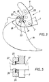
- the present invention overcomes this drawback, as will emerge from the description below given with reference to FIGS. 3 and 4.
- Figure 3 shows the attachment of a bucket 16 using a hooking member 3.
- the bucket 16 has a shaft 17, fixed relative to said bucket.
- the shaft 17 has two stops 18 and 19, diametrically opposite, capable of cooperating, when the bucket is locked, with two stops 20 and 21 carried by the fastening member 3.
- the stops have contact surfaces 22 and 23 similar to those 14 and 15.
- stops 20 and 21 are arranged towards the outside with respect to the axis of the shaft 17, but this arrangement can be reversed as shown in FIG. 5.
- the shaft 17 has two stops 24 and 25 capable, when the tool is locked, of cooperating with two stops 26 and 27 carried by the member 3.
Landscapes
- Engineering & Computer Science (AREA)
- Mechanical Engineering (AREA)
- Mining & Mineral Resources (AREA)
- Civil Engineering (AREA)
- General Engineering & Computer Science (AREA)
- Structural Engineering (AREA)
- Shovels (AREA)
- Earth Drilling (AREA)
- Load-Engaging Elements For Cranes (AREA)
- Forklifts And Lifting Vehicles (AREA)
Applications Claiming Priority (4)
| Application Number | Priority Date | Filing Date | Title |
|---|---|---|---|
| FR9411631 | 1994-09-29 | ||
| FR9411631A FR2725223B1 (fr) | 1994-09-29 | 1994-09-29 | Perfectionnements aux dispositifs pour fixer un outil a l'extremite du bras d'une pelle hydraulique ou analogue |
| FR9506566A FR2725224B1 (fr) | 1994-09-29 | 1995-06-02 | Perfectionnements aux dispositifs pour fixer un outil a l'extremite du bras d'une pelle hydraulique ou analogue |
| FR9506566 | 1995-06-02 |
Publications (2)
| Publication Number | Publication Date |
|---|---|
| EP0704577A1 true EP0704577A1 (de) | 1996-04-03 |
| EP0704577B1 EP0704577B1 (de) | 2000-02-09 |
Family
ID=26231431
Family Applications (1)
| Application Number | Title | Priority Date | Filing Date |
|---|---|---|---|
| EP95401790A Expired - Lifetime EP0704577B1 (de) | 1994-09-29 | 1995-07-28 | Schnellkupplung zum Befestigen der Arbeitswerkzeuge an einem Baggerausleger |
Country Status (6)
| Country | Link |
|---|---|
| EP (1) | EP0704577B1 (de) |
| AT (1) | ATE189726T1 (de) |
| DE (1) | DE69514973T2 (de) |
| DK (1) | DK0704577T3 (de) |
| ES (1) | ES2144588T3 (de) |
| FR (1) | FR2725224B1 (de) |
Cited By (3)
| Publication number | Priority date | Publication date | Assignee | Title |
|---|---|---|---|---|
| EP0810330A1 (de) * | 1996-05-30 | 1997-12-03 | Societe A Responsabilite Limitee : Morin Freres | Vorrichtung zum Befestigen eines Werkzeugs am Ende eines Armes eines Schaufelbaggers |
| FR2760029A1 (fr) * | 1997-02-24 | 1998-08-28 | Case France | Dispositif d'accrochage a une barre, et bras de manipulation d'outil le comportant |
| WO2007059721A1 (de) * | 2005-11-28 | 2007-05-31 | Robert Riedlberger | Zentriervorrichtung für schnellwechselvorrichtungen |
Families Citing this family (3)
| Publication number | Priority date | Publication date | Assignee | Title |
|---|---|---|---|---|
| DE102017000852B4 (de) * | 2017-01-31 | 2020-11-05 | Markus Riedlberger | Sicherheitsvorrichtung gegen unbeabsichtigtes Herausfallen von Werkzeugen aus einer Schnellwechselvorrichtung |
| DE102017130437A1 (de) * | 2017-12-19 | 2019-06-19 | Oilquick Deutschland Gmbh | Schnellwechsler, Adapter und Schnellwechselsystem |
| DE102017130436A1 (de) * | 2017-12-19 | 2019-06-19 | Oilquick Deutschland Gmbh | Adapter, Schnellwechsler und Schnellwechselsystem |
Citations (4)
| Publication number | Priority date | Publication date | Assignee | Title |
|---|---|---|---|---|
| FR2162156A1 (de) * | 1971-12-01 | 1973-07-13 | Verachtert Antonius | |
| FR2316387A1 (fr) * | 1975-06-21 | 1977-01-28 | Orenstein & Koppel Ag | Dispositif pour le changement rapide des instruments de travail des pelles hydrauliques |
| EP0438931A1 (de) | 1990-01-26 | 1991-07-31 | Societe En Nom Collectif Morin Freres | Vorrichtung zum Verbinden einer Schaufel, oder dergleichen, am Auslegerende eines Laders |
| DE9204711U1 (de) * | 1992-04-05 | 1992-07-16 | Eisenwerke Kaiserslautern Gmbh, 6750 Kaiserslautern | Schnellwechselvorrichtung für Baumaschinen |
-
1995
- 1995-06-02 FR FR9506566A patent/FR2725224B1/fr not_active Expired - Fee Related
- 1995-07-28 DK DK95401790T patent/DK0704577T3/da active
- 1995-07-28 AT AT95401790T patent/ATE189726T1/de active
- 1995-07-28 EP EP95401790A patent/EP0704577B1/de not_active Expired - Lifetime
- 1995-07-28 DE DE69514973T patent/DE69514973T2/de not_active Expired - Lifetime
- 1995-07-28 ES ES95401790T patent/ES2144588T3/es not_active Expired - Lifetime
Patent Citations (4)
| Publication number | Priority date | Publication date | Assignee | Title |
|---|---|---|---|---|
| FR2162156A1 (de) * | 1971-12-01 | 1973-07-13 | Verachtert Antonius | |
| FR2316387A1 (fr) * | 1975-06-21 | 1977-01-28 | Orenstein & Koppel Ag | Dispositif pour le changement rapide des instruments de travail des pelles hydrauliques |
| EP0438931A1 (de) | 1990-01-26 | 1991-07-31 | Societe En Nom Collectif Morin Freres | Vorrichtung zum Verbinden einer Schaufel, oder dergleichen, am Auslegerende eines Laders |
| DE9204711U1 (de) * | 1992-04-05 | 1992-07-16 | Eisenwerke Kaiserslautern Gmbh, 6750 Kaiserslautern | Schnellwechselvorrichtung für Baumaschinen |
Cited By (5)
| Publication number | Priority date | Publication date | Assignee | Title |
|---|---|---|---|---|
| EP0810330A1 (de) * | 1996-05-30 | 1997-12-03 | Societe A Responsabilite Limitee : Morin Freres | Vorrichtung zum Befestigen eines Werkzeugs am Ende eines Armes eines Schaufelbaggers |
| FR2749332A1 (fr) * | 1996-05-30 | 1997-12-05 | Morin Freres | Dispositif pour fixer un outil a l'extremite du bras d'une pelle mecanique |
| FR2760029A1 (fr) * | 1997-02-24 | 1998-08-28 | Case France | Dispositif d'accrochage a une barre, et bras de manipulation d'outil le comportant |
| WO2007059721A1 (de) * | 2005-11-28 | 2007-05-31 | Robert Riedlberger | Zentriervorrichtung für schnellwechselvorrichtungen |
| US7752781B2 (en) | 2005-11-28 | 2010-07-13 | Robert Riedlberger | Centring device for quick-change devices |
Also Published As
| Publication number | Publication date |
|---|---|
| DE69514973T2 (de) | 2000-07-27 |
| DK0704577T3 (da) | 2000-07-24 |
| FR2725224A1 (fr) | 1996-04-05 |
| DE69514973D1 (de) | 2000-03-16 |
| EP0704577B1 (de) | 2000-02-09 |
| ATE189726T1 (de) | 2000-02-15 |
| ES2144588T3 (es) | 2000-06-16 |
| FR2725224B1 (fr) | 1997-04-18 |
Similar Documents
| Publication | Publication Date | Title |
|---|---|---|
| EP1129259B1 (de) | Schnellkupplungsvorrichtung zur befestigung eines werkzeugs am ende des laderauslegers oder dgl | |
| EP0779951B1 (de) | Fernbedienbarer karabinerhaken, zum festmachen eines taues | |
| EP0438931B1 (de) | Vorrichtung zum Verbinden einer Schaufel, oder dergleichen, am Auslegerende eines Laders | |
| EP0704577B1 (de) | Schnellkupplung zum Befestigen der Arbeitswerkzeuge an einem Baggerausleger | |
| FR2743978A1 (fr) | Faucheuse avec organe de depose perfectionne | |
| FR2624248A1 (fr) | Dispositif de suspension destine a relier un outil a un moteur | |
| US5314292A (en) | Material clamping apparatus | |
| FR2725223A1 (fr) | Perfectionnements aux dispositifs pour fixer un outil a l'extremite du bras d'une pelle hydraulique ou analogue | |
| CA3150811C (fr) | Ensemble de couplage securise d'un outil sur un bras de travail d'un engin de travaux publics a fonctionnement ameliore | |
| FR2701047A1 (fr) | Système universel de liaison pour la solidarisation d'un accessoire, notamment d'un godet ou d'une benne, au bras articulé d'un engin de travaux publics. | |
| FR2785577A1 (fr) | Levier de changement de vitesse escamotable | |
| EP0490798A2 (de) | Kran, insbesondere für die Handhabung | |
| EP1587991B1 (de) | Vorrichtung zur einstellung eines am ende eines baggerarms oder der gleichen befestigten werkzeugs | |
| FR2694316A1 (fr) | Chargeur-excavateur-élévateur. | |
| EP0810330B1 (de) | Vorrichtung zum Befestigen eines Werkzeugs am Ende eines Armes eines Schaufelbaggers | |
| FR2854909A1 (fr) | Dispositif de couplage d'un outil a l'extremite de la fleche d'un engin, tel qu'une pelle hydraulique | |
| EP0256304B1 (de) | Maschine für Erdarbeiten | |
| CH641864A5 (fr) | Engin de terrassement. | |
| FR2494747A1 (fr) | Accessoire formant outil pour engin de terrassement et engin de terrassement equipe d'un tel accessoire | |
| FR2491901A3 (fr) | Crochet de securite | |
| FR2785951A1 (fr) | Attache rapide pour fixer un outil a l'extremite du bras d'un chargeur ou analogue | |
| FR2713681A1 (fr) | Dispositif de commande de la palette d'éjection d'un godet de pelleteuse. | |
| EP2010720B1 (de) | Vorrichtung zur verbindung eines werkzeugs mit dem ausleger einer maschine, wie zum beispiel einem hydraulikbagger | |
| FR2629114A1 (fr) | Vehicule pour travaux de terrassement | |
| FR2673422A1 (fr) | Dispositif de manutention d'un outil, adaptable sur un chargeur agricole. |
Legal Events
| Date | Code | Title | Description |
|---|---|---|---|
| PUAI | Public reference made under article 153(3) epc to a published international application that has entered the european phase |
Free format text: ORIGINAL CODE: 0009012 |
|
| 17P | Request for examination filed |
Effective date: 19960116 |
|
| AK | Designated contracting states |
Kind code of ref document: A1 Designated state(s): AT BE CH DE DK ES FR GB IT LI NL SE |
|
| 17Q | First examination report despatched |
Effective date: 19980707 |
|
| GRAG | Despatch of communication of intention to grant |
Free format text: ORIGINAL CODE: EPIDOS AGRA |
|
| GRAG | Despatch of communication of intention to grant |
Free format text: ORIGINAL CODE: EPIDOS AGRA |
|
| GRAH | Despatch of communication of intention to grant a patent |
Free format text: ORIGINAL CODE: EPIDOS IGRA |
|
| GRAH | Despatch of communication of intention to grant a patent |
Free format text: ORIGINAL CODE: EPIDOS IGRA |
|
| GRAA | (expected) grant |
Free format text: ORIGINAL CODE: 0009210 |
|
| AK | Designated contracting states |
Kind code of ref document: B1 Designated state(s): AT BE CH DE DK ES FR GB IT LI NL SE |
|
| REF | Corresponds to: |
Ref document number: 189726 Country of ref document: AT Date of ref document: 20000215 Kind code of ref document: T |
|
| REG | Reference to a national code |
Ref country code: CH Ref legal event code: EP |
|
| REF | Corresponds to: |
Ref document number: 69514973 Country of ref document: DE Date of ref document: 20000316 |
|
| ITF | It: translation for a ep patent filed | ||
| REG | Reference to a national code |
Ref country code: CH Ref legal event code: NV Representative=s name: BOVARD AG PATENTANWAELTE |
|
| REG | Reference to a national code |
Ref country code: ES Ref legal event code: FG2A Ref document number: 2144588 Country of ref document: ES Kind code of ref document: T3 |
|
| EN | Fr: translation not filed | ||
| GBT | Gb: translation of ep patent filed (gb section 77(6)(a)/1977) |
Effective date: 20000616 |
|
| REG | Reference to a national code |
Ref country code: DK Ref legal event code: T3 |
|
| EN4 | Fr: notification of non filing translation in an earlier bopi is erroneous | ||
| PLBE | No opposition filed within time limit |
Free format text: ORIGINAL CODE: 0009261 |
|
| STAA | Information on the status of an ep patent application or granted ep patent |
Free format text: STATUS: NO OPPOSITION FILED WITHIN TIME LIMIT |
|
| 26N | No opposition filed | ||
| REG | Reference to a national code |
Ref country code: GB Ref legal event code: IF02 |
|
| REG | Reference to a national code |
Ref country code: FR Ref legal event code: CL |
|
| REG | Reference to a national code |
Ref country code: CH Ref legal event code: PFA Owner name: SOCIETE A RESPONSABILITE LIMITEE : MORIN FRERES Free format text: SOCIETE A RESPONSABILITE LIMITEE : MORIN FRERES#LIEUDIT "LES BRETECHES"#F-45740 LAILLY EN VAL (FR) -TRANSFER TO- SOCIETE A RESPONSABILITE LIMITEE : MORIN FRERES#LIEUDIT "LES BRETECHES"#F-45740 LAILLY EN VAL (FR) |
|
| PGFP | Annual fee paid to national office [announced via postgrant information from national office to epo] |
Ref country code: DK Payment date: 20110708 Year of fee payment: 17 |
|
| PGFP | Annual fee paid to national office [announced via postgrant information from national office to epo] |
Ref country code: AT Payment date: 20110731 Year of fee payment: 17 Ref country code: SE Payment date: 20110722 Year of fee payment: 17 |
|
| REG | Reference to a national code |
Ref country code: SE Ref legal event code: EUG |
|
| REG | Reference to a national code |
Ref country code: AT Ref legal event code: MM01 Ref document number: 189726 Country of ref document: AT Kind code of ref document: T Effective date: 20120728 |
|
| REG | Reference to a national code |
Ref country code: DK Ref legal event code: EBP |
|
| PG25 | Lapsed in a contracting state [announced via postgrant information from national office to epo] |
Ref country code: SE Free format text: LAPSE BECAUSE OF NON-PAYMENT OF DUE FEES Effective date: 20120729 |
|
| PG25 | Lapsed in a contracting state [announced via postgrant information from national office to epo] |
Ref country code: AT Free format text: LAPSE BECAUSE OF NON-PAYMENT OF DUE FEES Effective date: 20120728 |
|
| PG25 | Lapsed in a contracting state [announced via postgrant information from national office to epo] |
Ref country code: DK Free format text: LAPSE BECAUSE OF NON-PAYMENT OF DUE FEES Effective date: 20120731 |
|
| PGFP | Annual fee paid to national office [announced via postgrant information from national office to epo] |
Ref country code: CH Payment date: 20140715 Year of fee payment: 20 Ref country code: DE Payment date: 20140711 Year of fee payment: 20 Ref country code: NL Payment date: 20140630 Year of fee payment: 20 |
|
| PGFP | Annual fee paid to national office [announced via postgrant information from national office to epo] |
Ref country code: FR Payment date: 20140604 Year of fee payment: 20 Ref country code: GB Payment date: 20140717 Year of fee payment: 20 Ref country code: ES Payment date: 20140725 Year of fee payment: 20 |
|
| PGFP | Annual fee paid to national office [announced via postgrant information from national office to epo] |
Ref country code: IT Payment date: 20140714 Year of fee payment: 20 |
|
| PGFP | Annual fee paid to national office [announced via postgrant information from national office to epo] |
Ref country code: BE Payment date: 20140730 Year of fee payment: 20 |
|
| REG | Reference to a national code |
Ref country code: DE Ref legal event code: R071 Ref document number: 69514973 Country of ref document: DE |
|
| REG | Reference to a national code |
Ref country code: CH Ref legal event code: PL |
|
| REG | Reference to a national code |
Ref country code: GB Ref legal event code: PE20 Expiry date: 20150727 |
|
| PG25 | Lapsed in a contracting state [announced via postgrant information from national office to epo] |
Ref country code: GB Free format text: LAPSE BECAUSE OF EXPIRATION OF PROTECTION Effective date: 20150727 |
|
| REG | Reference to a national code |
Ref country code: ES Ref legal event code: FD2A Effective date: 20151104 |
|
| PG25 | Lapsed in a contracting state [announced via postgrant information from national office to epo] |
Ref country code: ES Free format text: LAPSE BECAUSE OF EXPIRATION OF PROTECTION Effective date: 20150729 |