EP0704604A2 - Arbre à cames - Google Patents
Arbre à cames Download PDFInfo
- Publication number
- EP0704604A2 EP0704604A2 EP95112586A EP95112586A EP0704604A2 EP 0704604 A2 EP0704604 A2 EP 0704604A2 EP 95112586 A EP95112586 A EP 95112586A EP 95112586 A EP95112586 A EP 95112586A EP 0704604 A2 EP0704604 A2 EP 0704604A2
- Authority
- EP
- European Patent Office
- Prior art keywords
- camshaft
- bearing
- section
- flange
- connecting flange
- Prior art date
- Legal status (The legal status is an assumption and is not a legal conclusion. Google has not performed a legal analysis and makes no representation as to the accuracy of the status listed.)
- Withdrawn
Links
Images
Classifications
-
- F—MECHANICAL ENGINEERING; LIGHTING; HEATING; WEAPONS; BLASTING
- F01—MACHINES OR ENGINES IN GENERAL; ENGINE PLANTS IN GENERAL; STEAM ENGINES
- F01L—CYCLICALLY OPERATING VALVES FOR MACHINES OR ENGINES
- F01L1/00—Valve-gear or valve arrangements, e.g. lift-valve gear
- F01L1/02—Valve drive
- F01L1/04—Valve drive by means of cams, camshafts, cam discs, eccentrics or the like
- F01L1/047—Camshafts
-
- F—MECHANICAL ENGINEERING; LIGHTING; HEATING; WEAPONS; BLASTING
- F01—MACHINES OR ENGINES IN GENERAL; ENGINE PLANTS IN GENERAL; STEAM ENGINES
- F01L—CYCLICALLY OPERATING VALVES FOR MACHINES OR ENGINES
- F01L1/00—Valve-gear or valve arrangements, e.g. lift-valve gear
- F01L1/02—Valve drive
- F01L1/04—Valve drive by means of cams, camshafts, cam discs, eccentrics or the like
- F01L1/047—Camshafts
- F01L2001/0476—Camshaft bearings
Definitions
- the invention relates to a camshaft for an engine consisting of several sections, which is mounted several times in a crankcase in the bearing shells of a bearing bracket.
- the object of the invention is to improve an embodiment of a composite camshaft for an engine, which can be easily installed or removed.
- each camshaft section comprises a connecting flange at one end and a bearing journal at the opposite other end, and in the operating state the connecting flange of the section is releasably connected to a bearing journal of the subsequent section via flange screws and the section is and dismantled condition between the other sections around the bearing pin with its flange-side end is arranged tiltable.
- the camshaft sections in can be replaced or exchanged in a simple manner.
- the sections each have a connecting flange at the end and a bearing journal, so that the camshaft as a whole is formed by a mutual screw connection between the connecting flange and the bearing journal of the sections.
- the floating bearing bush receiving the journal is axially displaced. This is made possible by loosening a screw-in bolt that holds the bearing bush axially and against rotating.
- the connecting flanges have a diameter that exceeds the enveloping circles of all cams.
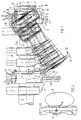
- a camshaft 1 for an engine comprises a plurality of camshaft sections 2, 3 and 4, further possible sections not being shown.
- Each section has a connecting flange 6 at one end 5 and a bearing journal 8 at the other end 7, which is held in a so-called wobble bearing arrangement consisting of a bearing shell 9 in a bearing bracket 10.
- the sections 2, 3 and 4 are screwed together using flange screws 12 which connect the connecting flange 6 of one section to the bearing journal 8 of the subsequent section.
- the camshaft sections 2, 3 and 4 are designed as one-piece forged components with the connecting flange 6 and the bearing pin 8.
- the bearing pin 8 is mounted in the bearing shell 9 of the bearing bracket 10 of the crankcase, which is axially fixed via at least one screw-in bolt 11 and secured against rotation.
- the bearing bridge has a cast recess 14 which forms a free space for the connecting flange 6 during installation and removal.
- the bearing pins 8 of the sections 2, 3 and 4 preferably have a diameter which is larger than the enveloping circles of all the cams 14. This enables a problem-free installation and removal of a completely assembled camshaft 1 axially in the engine.
- a camshaft for the engine which consists of several assembled sections.
- each section has a connecting flange and a bearing journal.
- the intermediate camshaft section is removed by tilting this section out between the two subsequent further sections, with a tilting movement around the bearing journal in the bearing shell and the flange-side end of the section being pivoted out first on one side.
Landscapes
- Engineering & Computer Science (AREA)
- Mechanical Engineering (AREA)
- General Engineering & Computer Science (AREA)
- Valve-Gear Or Valve Arrangements (AREA)
Applications Claiming Priority (2)
| Application Number | Priority Date | Filing Date | Title |
|---|---|---|---|
| DE19944434982 DE4434982A1 (de) | 1994-09-30 | 1994-09-30 | Nockenwelle |
| DE4434982 | 1994-09-30 |
Publications (2)
| Publication Number | Publication Date |
|---|---|
| EP0704604A2 true EP0704604A2 (fr) | 1996-04-03 |
| EP0704604A3 EP0704604A3 (fr) | 1996-12-11 |
Family
ID=6529617
Family Applications (1)
| Application Number | Title | Priority Date | Filing Date |
|---|---|---|---|
| EP95112586A Withdrawn EP0704604A3 (fr) | 1994-09-30 | 1995-08-10 | Arbre à cames |
Country Status (2)
| Country | Link |
|---|---|
| EP (1) | EP0704604A3 (fr) |
| DE (1) | DE4434982A1 (fr) |
Cited By (1)
| Publication number | Priority date | Publication date | Assignee | Title |
|---|---|---|---|---|
| EP1057979A3 (fr) * | 1999-06-04 | 2002-11-27 | Caterpillar Inc. | Arbre à cames assemblé pour moteur à combustion interne |
Family Cites Families (4)
| Publication number | Priority date | Publication date | Assignee | Title |
|---|---|---|---|---|
| DE1141492B (de) * | 1960-06-23 | 1962-12-20 | Motoren Werke Mannheim Ag | Steuerwellenlagerung fuer Verbrennungskraftmaschinen |
| FI62711C (fi) * | 1976-02-18 | 1983-02-10 | Waertsilae Oy Ab | Nockaxel och foerfarande foer dess montering |
| CH612727A5 (fr) * | 1976-12-10 | 1979-08-15 | Sulzer Ag | |
| DE3923250A1 (de) * | 1989-07-14 | 1991-01-24 | Mak Maschinenbau Krupp | Steuerwelle |
-
1994
- 1994-09-30 DE DE19944434982 patent/DE4434982A1/de not_active Withdrawn
-
1995
- 1995-08-10 EP EP95112586A patent/EP0704604A3/fr not_active Withdrawn
Non-Patent Citations (1)
| Title |
|---|
| None |
Cited By (1)
| Publication number | Priority date | Publication date | Assignee | Title |
|---|---|---|---|---|
| EP1057979A3 (fr) * | 1999-06-04 | 2002-11-27 | Caterpillar Inc. | Arbre à cames assemblé pour moteur à combustion interne |
Also Published As
| Publication number | Publication date |
|---|---|
| EP0704604A3 (fr) | 1996-12-11 |
| DE4434982A1 (de) | 1996-04-04 |
Similar Documents
| Publication | Publication Date | Title |
|---|---|---|
| DE69727144T2 (de) | Montage vorrichtung | |
| DE4001379C2 (de) | Pumpenlaufrad | |
| DE69902944T2 (de) | Befestigungsvorrichtung zum schnellen an- bzw. abkoppeln eines bauteils an eine bzw. von einer auflagefläche | |
| DE29522251U1 (de) | Einrichtung zum Klemmen einer Lageranordnung an eine verlängerte Welle | |
| DE2424262A1 (de) | Gewindelose spannvorrichtung | |
| DE2011777C3 (fr) | ||
| DE2648144C2 (de) | Mittenfreie Wälzlager-Drehverbindung | |
| DE1293549B (de) | Stimmvorrichtung fuer Gitarren | |
| DE19528434B4 (de) | Bremsscheibe | |
| EP0058781A1 (fr) | Cylindre extracteur pour des balles de matières fibreuses | |
| DE2412606A1 (de) | Kugelspindel | |
| DE1284732B (de) | Bremsscheibe fuer Scheibenbremsen, insbesondere von Schienenfahrzeugen | |
| DE3224762C2 (fr) | ||
| DE3427259C2 (de) | Rolltor - Antrieb | |
| DE10238415B4 (de) | Gleitlager für eine Welle eines Abgasturboladers | |
| EP0704604A2 (fr) | Arbre à cames | |
| DE2936068C2 (fr) | ||
| EP0243577A2 (fr) | Vilebrequin en matière ferreuse pour machines à piston | |
| DE20208133U1 (de) | Gleitlager zur axialen und radialen Lagerung | |
| DE3639168A1 (de) | Hubschrauber-hauptrotor | |
| DE69502511T2 (de) | Zusammenbau einer Kipphebelwelle in einem Zylinderkopf einer Brennkraftmaschine | |
| DE69008383T2 (de) | Verfahren und Vorrichtung zur spielfreien Montage eines sich drehenden Teiles zwischen zwei Lagern. | |
| DE4339978A1 (de) | Welle-/Nabe-Verbindung | |
| DE10296634T5 (de) | Entrindungswellenanordnung für einen Entrindungsmechanismus | |
| DE3931737A1 (de) | Eigenantriebsspindel |
Legal Events
| Date | Code | Title | Description |
|---|---|---|---|
| PUAI | Public reference made under article 153(3) epc to a published international application that has entered the european phase |
Free format text: ORIGINAL CODE: 0009012 |
|
| AK | Designated contracting states |
Kind code of ref document: A2 Designated state(s): CH DE FR LI NL |
|
| PUAL | Search report despatched |
Free format text: ORIGINAL CODE: 0009013 |
|
| RHK1 | Main classification (correction) |
Ipc: F01L 1/047 |
|
| AK | Designated contracting states |
Kind code of ref document: A3 Designated state(s): CH DE FR LI NL |
|
| 17P | Request for examination filed |
Effective date: 19961210 |
|
| RAP1 | Party data changed (applicant data changed or rights of an application transferred) |
Owner name: MAK MOTOREN GMBH |
|
| 17Q | First examination report despatched |
Effective date: 19970602 |
|
| STAA | Information on the status of an ep patent application or granted ep patent |
Free format text: STATUS: THE APPLICATION HAS BEEN WITHDRAWN |
|
| 18W | Application withdrawn |
Withdrawal date: 19971111 |