EP0704655B1 - Light guide lighting system for forming a thin lighting device - Google Patents
Light guide lighting system for forming a thin lighting device Download PDFInfo
- Publication number
- EP0704655B1 EP0704655B1 EP95115346A EP95115346A EP0704655B1 EP 0704655 B1 EP0704655 B1 EP 0704655B1 EP 95115346 A EP95115346 A EP 95115346A EP 95115346 A EP95115346 A EP 95115346A EP 0704655 B1 EP0704655 B1 EP 0704655B1
- Authority
- EP
- European Patent Office
- Prior art keywords
- lighting system
- facing surfaces
- rays
- light
- pairs
- Prior art date
- Legal status (The legal status is an assumption and is not a legal conclusion. Google has not performed a legal analysis and makes no representation as to the accuracy of the status listed.)
- Expired - Lifetime
Links
- 239000000463 material Substances 0.000 claims description 21
- 230000000712 assembly Effects 0.000 claims description 6
- 238000000429 assembly Methods 0.000 claims description 6
- 239000012780 transparent material Substances 0.000 claims description 5
- 239000012080 ambient air Substances 0.000 claims description 2
- 239000012530 fluid Substances 0.000 claims description 2
- 239000011521 glass Substances 0.000 claims description 2
- 229920003229 poly(methyl methacrylate) Polymers 0.000 claims description 2
- 239000004926 polymethyl methacrylate Substances 0.000 claims description 2
- 239000004033 plastic Substances 0.000 claims 1
- 229920003023 plastic Polymers 0.000 claims 1
- 239000004973 liquid crystal related substance Substances 0.000 description 6
- 230000013011 mating Effects 0.000 description 3
- 230000003287 optical effect Effects 0.000 description 2
- 238000010276 construction Methods 0.000 description 1
- 238000004519 manufacturing process Methods 0.000 description 1
- 239000007769 metal material Substances 0.000 description 1
- 238000013021 overheating Methods 0.000 description 1
- 239000012815 thermoplastic material Substances 0.000 description 1
Images


Classifications
-
- G—PHYSICS
- G02—OPTICS
- G02B—OPTICAL ELEMENTS, SYSTEMS OR APPARATUS
- G02B6/00—Light guides; Structural details of arrangements comprising light guides and other optical elements, e.g. couplings
- G02B6/0001—Light guides; Structural details of arrangements comprising light guides and other optical elements, e.g. couplings specially adapted for lighting devices or systems
- G02B6/0011—Light guides; Structural details of arrangements comprising light guides and other optical elements, e.g. couplings specially adapted for lighting devices or systems the light guides being planar or of plate-like form
- G02B6/0033—Means for improving the coupling-out of light from the light guide
- G02B6/005—Means for improving the coupling-out of light from the light guide provided by one optical element, or plurality thereof, placed on the light output side of the light guide
- G02B6/0055—Reflecting element, sheet or layer
-
- F—MECHANICAL ENGINEERING; LIGHTING; HEATING; WEAPONS; BLASTING
- F21—LIGHTING
- F21V—FUNCTIONAL FEATURES OR DETAILS OF LIGHTING DEVICES OR SYSTEMS THEREOF; STRUCTURAL COMBINATIONS OF LIGHTING DEVICES WITH OTHER ARTICLES, NOT OTHERWISE PROVIDED FOR
- F21V5/00—Refractors for light sources
- F21V5/002—Refractors for light sources using microoptical elements for redirecting or diffusing light
-
- G—PHYSICS
- G02—OPTICS
- G02B—OPTICAL ELEMENTS, SYSTEMS OR APPARATUS
- G02B6/00—Light guides; Structural details of arrangements comprising light guides and other optical elements, e.g. couplings
- G02B6/0001—Light guides; Structural details of arrangements comprising light guides and other optical elements, e.g. couplings specially adapted for lighting devices or systems
- G02B6/0005—Light guides; Structural details of arrangements comprising light guides and other optical elements, e.g. couplings specially adapted for lighting devices or systems the light guides being of the fibre type
- G02B6/001—Light guides; Structural details of arrangements comprising light guides and other optical elements, e.g. couplings specially adapted for lighting devices or systems the light guides being of the fibre type the light being emitted along at least a portion of the lateral surface of the fibre
-
- G—PHYSICS
- G02—OPTICS
- G02B—OPTICAL ELEMENTS, SYSTEMS OR APPARATUS
- G02B6/00—Light guides; Structural details of arrangements comprising light guides and other optical elements, e.g. couplings
- G02B6/0001—Light guides; Structural details of arrangements comprising light guides and other optical elements, e.g. couplings specially adapted for lighting devices or systems
- G02B6/0011—Light guides; Structural details of arrangements comprising light guides and other optical elements, e.g. couplings specially adapted for lighting devices or systems the light guides being planar or of plate-like form
- G02B6/0075—Arrangements of multiple light guides
- G02B6/0076—Stacked arrangements of multiple light guides of the same or different cross-sectional area
-
- G—PHYSICS
- G02—OPTICS
- G02B—OPTICAL ELEMENTS, SYSTEMS OR APPARATUS
- G02B6/00—Light guides; Structural details of arrangements comprising light guides and other optical elements, e.g. couplings
- G02B6/24—Coupling light guides
- G02B6/42—Coupling light guides with opto-electronic elements
- G02B6/4298—Coupling light guides with opto-electronic elements coupling with non-coherent light sources and/or radiation detectors, e.g. lamps, incandescent bulbs, scintillation chambers
-
- G—PHYSICS
- G02—OPTICS
- G02B—OPTICAL ELEMENTS, SYSTEMS OR APPARATUS
- G02B6/00—Light guides; Structural details of arrangements comprising light guides and other optical elements, e.g. couplings
- G02B6/0001—Light guides; Structural details of arrangements comprising light guides and other optical elements, e.g. couplings specially adapted for lighting devices or systems
- G02B6/0011—Light guides; Structural details of arrangements comprising light guides and other optical elements, e.g. couplings specially adapted for lighting devices or systems the light guides being planar or of plate-like form
- G02B6/0013—Means for improving the coupling-in of light from the light source into the light guide
- G02B6/0023—Means for improving the coupling-in of light from the light source into the light guide provided by one optical element, or plurality thereof, placed between the light guide and the light source, or around the light source
- G02B6/003—Lens or lenticular sheet or layer
Definitions
- the present invention relates to a lighting system substantially comprising a pair of light guides so formed as to present a very small dimension in one direction, and which provides for emitting light in that direction; the light being generated by a source located on one side or on either side of the light guides, and which emits light in a direction perpendicular to the former.
- US Patent n. 5 235 443 relates to a liquid crystal device of the aforementioned type, which substantially comprises a pair of light guides made of rigid, transparent material and defining a number of facing surfaces; a layer of Colysteric liquid crystal between the surfaces; and a light source located on one side of the guides, and generating light in a direction forming a predetermined angle with said facing surfaces.
- the above device substantially constitutes a polarized light generator, the polarizing state of which may be appropriately controlled by means of liquid crystals.
- Liquid crystal devices of the type described in the above patent are seldom employable for forming an actual lighting device.
- the intensity distribution of the light generated by such devices in fact, can only be varied within a very small range, and the divergence of the beam so formed fails to fall within the range of most commonly used lighting devices.
- liquid crystal lighting devices involve a painstaking manufacturing process which therefore makes them unsuitable for this type of application.
- a lighting system substantially comprising:
- the lighting system substantially comprises at least a pair of light guides 1 and 2 conveniently made of rigid, transparent material, e.g. thermoplastic material or glass, and defining a number of pairs of facing surfaces 3-4, 5-6, each pair defined by a surface (3 and 6) of one (1) of the light guides, and by a surface (4 and 5) of the other (2) light guide.
- a pair of light guides 1 and 2 conveniently made of rigid, transparent material, e.g. thermoplastic material or glass, and defining a number of pairs of facing surfaces 3-4, 5-6, each pair defined by a surface (3 and 6) of one (1) of the light guides, and by a surface (4 and 5) of the other (2) light guide.
- the system also comprises a light source 7 for generating a stream of controlled-divergence rays 8, the direction of which forms a predetermined angle ⁇ ( Figure 1) with surface pairs 3,4, 5,6.
- a layer 11 of at least partly transparent material the structural characteristics of which differ from those of the layer between the facing surfaces 5-6 in the following pair in the direction of rays 8.
- pairs of facing surfaces 3-4, 5-6 of light guides 1-2 present, as shown in Figure 1, a profile in the form of an isosceles triangle with a 90° angle at the apex, layers 11a, 11b, 11c, 11d, ... form part of a single continuous strip of material interposed between the surfaces, in which case, the structural characteristics of the layers are varied in the direction of rays 8 by simply varying the thickness or by gradually varying the refraction index of the layers.
- the structural characteristics of the layers are varied by varying the reflectance of the layers, for which purpose, a layer of reflecting metal material 13 varying in thickness in the direction of rays 8 is deposited on a layer of transparent base material 12.
- layer 13 may be deposited in known manner directly on to one of the two light guides.
- Layer 11 interposed between the pairs of facing surfaces of light guides 1 and 2 may also comprise a diffraction grating 14 - as in the Figure 4 embodiment - which, as is known, substantially comprises a number of diffraction projections 15 of appropriate shape and size and which may project, for example, from a supporting layer 16 or be formed directly on surfaces 3, 4, 5 and 6 of light guides 1 and 2.
- the spacing p ( Figure 4) of diffraction projections 15 has been found to preferably range between 0.5 and 0.7 micron, and the ratio of the height h of projections 15 to the thickness of supporting layer 16 to preferably range between 0.5 and 2.
- the Figure 1 embodiment of the system according to the present invention also comprises a perfectly reflecting surface 17 located on one side of light guides 1, 2 and in a plane substantially parallel to the intersections of surfaces 4, 5 and 3,6 of light guides 1 and 2.
- the lighting system also comprises an assembly 18 of microlenses substantially located in a plane parallel to that of reflecting surface 17.
- Assembly 18 may comprise a number of refracting or combined refracting-diffracting lenses 21 which may be arranged in any manner for receiving and producing the required divergence of rays 8 which, as described later on, are directed towards lenses 21 in a direction substantially perpendicular to their propagation direction.
- Source 7 and light guides 1 and 2 may conveniently be connected by a refracting, diffracting or combined refracting-diffracting lens (or lens system) 22 interposed between source 7 and one of the smaller sides of the light guide 1-2 assembly, and which provides for so controlling the divergence of the beam entering guides 1 and 2 as to obtain, for example, a beam of substantially parallel rays 8 as shown in Figure 1.
- a refracting, diffracting or combined refracting-diffracting lens (or lens system) 22 interposed between source 7 and one of the smaller sides of the light guide 1-2 assembly, and which provides for so controlling the divergence of the beam entering guides 1 and 2 as to obtain, for example, a beam of substantially parallel rays 8 as shown in Figure 1.
- the lighting system according to the present invention operates as follows.
- each ray inside guides 1 and 2 will be described with reference to ray 8a entering light guide 1.
- a reflected ray 8b is generated substantially perpendicular to the direction of ray 8a and towards microlens assembly 18;
- ray 8a is also refracted at the above interface and at the following interface between surface 4 and the mating surface of layer 11a, to generate a ray 8c inside light guide 2 and directed substantially parallel to ray 8a;
- ray 8c is reflected perpendicularly to generate a ray 8e which is reflected by perfectly reflecting surface 17 to generate a ray 8d towards microlens assembly 18; and
- ray 8c is also refracted at the interface between surface 5 and the mating surface of layer 11b, and again at the interface between the other surface of layer 11b and surface 6 of light guide 1 to
- Ray 8f is now in the same condition as ray 8a, and is therefore reflected and refracted by the following interfaces in the same way.
- a portion of the light impinging on light guides 1 and 2 is therefore reflected towards microlens assembly 18, while another portion of the same light is transmitted to the following pairs of facing surfaces of the two light guides.
- the direction of rays 8b and 8d directed towards microlens assembly 18 is modified by assembly 18 to obtain an outgoing light diverging as required.
- a given ratio may be obtained between the energy of the reflected rays (e.g. 8b and 8d) and that of the rays (e.g. 8c and 8f) transmitted along the guides, so as to obtain a given light intensity distribution of the reflected rays and a predetermined light pattern to meet the requirements of a given lighting device.
- the ratio of the reflected light energy to that of the transmitted light depends on the structural characteristics of the material interposed between the facing surfaces of the light guides and which may be selected accordingly.
- the Figure 2 embodiment of the lighting system according to the present invention differs from that in Figure 1 in that facing surfaces 3-4 and 5-6 of light guides 1 and 2, as opposed to being the same size, increase in size - that is, the triangular profile of the facing surfaces increases in height - in the direction of the rays. Varying the geometric characteristics of the facing surfaces of the two light guides in this way provides for varying the light intensity distribution of the system, as shown in Figure 2, and bearing in mind that certain rays, such as ray 24 impinging on interface 23, may come directly from the light source, whereas others, such as ray 25, impinge on interface 23 after first being reflected at interfaces 26, 27, 28 and 29.
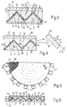
- the light guides in the Figure 1 and 2 embodiments may conveniently comprise a flat supporting element 30 from which project prismed portions 31, each with a profile substantially in the form of an isosceles triangle with a 45° angle at the apex, and which generate pairs of facing surfaces 3-4 and 5-6.
- prismed portions 30 and 31 are circular and coaxial, as shown clearly, in which case, provision is made for a number of light sources 7 arranged peripherally about the two light guides, and each generating light in a substantially radial direction.
- facing surfaces 3 and 4 of light guides 1 and 2 are oriented the same way in relation to the direction of the rays; and the layers of material 11a, 11b, 11c and 11d of different structural characteristics and interposed between facing surfaces 3 and 4 are separate.
- facing surfaces 3-4 are curved, so that the rays are reflected in different desired directions, and divergence of the beam emitted by the system may be controlled without a microlens assembly such as 18 in the Figure 1 embodiment.
- the Figure 8 and 9 embodiment substantially corresponds to that in Figure 7, except that the light guides are symmetrically circular.
- the system substantially comprises two light guide assemblies 32 and 33, each comprising a number of substantially semicircular, coaxial light guides. Assemblies 32 and 33 are connected at a diametrical surface 34, and the facing surfaces 3-4 ( Figure 9) of each guide are so oriented as to lie substantially in the same plane in relation to a ray in a substantially radial direction.
- light sources 7 are arranged peripherally about one of assemblies 32 and 33, as shown clearly in Figure 8, so that the rays emitted by each source impinge on the interfaces of both assemblies, as shown clearly in Figure 9.
- Light source 7 may be of any type, e.g. comprising one or more incandescent, fluorescent or discharge lamps; may be punctiform, e.g. a LED type; and may be provided with an elliptical reflector 36 or a parabolic reflector 37 as shown respectively in Figures 11 and 12.
- the beam is focused, so a refracting, diffracting or combined refracting-diffracting lens 38 is provided to control the divergence of the beam impinging on the light guides.
- divergence may be controlled solely by the parabolic reflector.
- the Figure 13 arrangement may be adopted, wherein an appropriate separating diffraction grating 39 is provided for separating the infrared rays 40 from those emitted by the source, and directing them in an appropriate direction.
- the lighting system according to the invention may comprise a transparent screen 180 presenting an integral or applied microlens assembly 18; a rear panel 170 facing screen 180 and possibly forming part of a known cup-shaped casing (not shown), to close the front of which, screen 180 is fitted in fluidtight manner at a predetermined distance from panel 170; and an undulated element 11 located between and parallel to panel 170 and screen 180 and in the propagation direction of rays 8.
- undulated element 11 is defined by pairs of facing surfaces 3-4, 5-6, by which it is divided into a number of adjacent portions 11a, 11b, 11c, 11d, ... inclined in relation to the propagation direction of rays 8 and presenting alternate opposite angles; and each of said portions 11a, 11b, ... is made of said material presenting different structural characteristics from one portion to another.
- undulated element 11 is made in one piece, and comprises appropriately molded PMMA, for example, by forming each portion 11a, 11b, ... of a different thickness, or by injecting the material into the mold using different nozzles, so that each portion 11a, 11b, ... is formed of material with different optical characteristics.
- the light guides are therefore defined by respective gaps 1a, 2a, either empty or filled with a transparent fluid, normally ambient air and possibly of desired optical characteristics (in which case, each gap 1a, 2a is fluidtight), and defined respectively between undulated element 11 and panel 170, and between undulated element 11 and screen 180.
Landscapes
- Physics & Mathematics (AREA)
- General Physics & Mathematics (AREA)
- Optics & Photonics (AREA)
- Engineering & Computer Science (AREA)
- General Engineering & Computer Science (AREA)
- Planar Illumination Modules (AREA)
- Light Guides In General And Applications Therefor (AREA)
Applications Claiming Priority (2)
| Application Number | Priority Date | Filing Date | Title |
|---|---|---|---|
| ITTO940773 | 1994-09-30 | ||
| IT94TO000773A IT1268610B1 (it) | 1994-09-30 | 1994-09-30 | Sistema di illuminazione a guide di luce atto a realizzare un dispositivo di illuminazione sottile |
Publications (2)
| Publication Number | Publication Date |
|---|---|
| EP0704655A1 EP0704655A1 (en) | 1996-04-03 |
| EP0704655B1 true EP0704655B1 (en) | 1999-03-24 |
Family
ID=11412801
Family Applications (1)
| Application Number | Title | Priority Date | Filing Date |
|---|---|---|---|
| EP95115346A Expired - Lifetime EP0704655B1 (en) | 1994-09-30 | 1995-09-28 | Light guide lighting system for forming a thin lighting device |
Country Status (4)
| Country | Link |
|---|---|
| EP (1) | EP0704655B1 (it) |
| DE (1) | DE69508511T2 (it) |
| ES (1) | ES2131245T3 (it) |
| IT (1) | IT1268610B1 (it) |
Cited By (7)
| Publication number | Priority date | Publication date | Assignee | Title |
|---|---|---|---|---|
| US9367490B2 (en) | 2014-06-13 | 2016-06-14 | Microsoft Technology Licensing, Llc | Reversible connector for accessory devices |
| US9384334B2 (en) | 2014-05-12 | 2016-07-05 | Microsoft Technology Licensing, Llc | Content discovery in managed wireless distribution networks |
| US9430667B2 (en) | 2014-05-12 | 2016-08-30 | Microsoft Technology Licensing, Llc | Managed wireless distribution network |
| US9459398B2 (en) | 2013-07-18 | 2016-10-04 | Quarkstar Llc | Illumination device in which source light injection is non-parallel to device's optical axis |
| US9599308B2 (en) | 2012-12-28 | 2017-03-21 | 3M Innovative Properties Company | Hybrid taillight article |
| US9658382B2 (en) | 2014-03-28 | 2017-05-23 | Quarkstar Llc | Luminaire module having a light guide with redirecting interfaces |
| US10691445B2 (en) | 2014-06-03 | 2020-06-23 | Microsoft Technology Licensing, Llc | Isolating a portion of an online computing service for testing |
Families Citing this family (23)
| Publication number | Priority date | Publication date | Assignee | Title |
|---|---|---|---|---|
| WO1997014075A1 (en) | 1995-10-12 | 1997-04-17 | Ibm Japan Ltd. | Light-transmitting material, planar light source device and liquid crystal display device |
| FR2751398B1 (fr) * | 1996-07-16 | 1998-08-28 | Thomson Csf | Dispositif d'eclairage et application a l'eclairage d'un ecran transmissif |
| US6827456B2 (en) | 1999-02-23 | 2004-12-07 | Solid State Opto Limited | Transreflectors, transreflector systems and displays and methods of making transreflectors |
| JP3574365B2 (ja) | 1999-05-28 | 2004-10-06 | ユニベルシテ・ド・リエージュ | 照明装置、その用い方及び製造方法 |
| EP1055872A1 (en) * | 1999-05-28 | 2000-11-29 | University of Liege | Illumination device |
| GB9919689D0 (en) * | 1999-08-19 | 1999-10-20 | Microsharp Corp Limited | Back-lighting arrangement and the like |
| US6646813B2 (en) * | 2000-12-21 | 2003-11-11 | Light Prescriptions Innovators, Llc. | Optical transformer for small light sources |
| EP1451502B1 (en) | 2001-12-05 | 2010-05-26 | Rambus International Ltd | Transreflectors, transreflector systems and displays and methods of making transreflectors |
| DE10347763B4 (de) * | 2003-10-14 | 2014-07-24 | BSH Bosch und Siemens Hausgeräte GmbH | Gargerät mit einer Türscheibe mit einem Lichtstreubereich |
| KR100677122B1 (ko) * | 2004-06-23 | 2007-02-02 | 삼성전자주식회사 | 백라이트 유닛용 도광판 및 그 제조방법 |
| DE102008019118A1 (de) * | 2008-04-16 | 2009-10-22 | Osram Opto Semiconductors Gmbh | Infrarot-Beleuchtungssystem und Kfz-Scheinwerfer mit einem Infrarot-Beleuchtungssystem |
| WO2010122329A1 (en) * | 2009-04-20 | 2010-10-28 | Bae Systems Plc | Improvements in optical waveguides |
| EP2244112A1 (en) * | 2009-04-20 | 2010-10-27 | BAE Systems PLC | Improvements in optical waveguides |
| DE102010012757A1 (de) * | 2010-03-25 | 2011-09-29 | Hella Kgaa Hueck & Co. | Optisches Bauelement eines Leuchtmittels sowie Leuchtmittel |
| DE102013214697B4 (de) | 2013-07-26 | 2022-07-14 | tooz technologies GmbH | Anzeigevorrichtung mit einem optischen Element, das eine Fresnel-Struktur umfasst,sowie Verfahren zur Herstellung eines solchen optischen Elementes |
| WO2015044305A1 (de) | 2013-09-27 | 2015-04-02 | Carl Zeiss Ag | Brillenglas für eine auf den kopf eines benutzers aufsetzbare und ein bild erzeugende anzeigevorrichtung |
| DE102013219622B4 (de) * | 2013-09-27 | 2021-01-14 | tooz technologies GmbH | Optisches Element und Anzeigevorrichtung mit einem solchen optischen Element |
| US9614724B2 (en) | 2014-04-21 | 2017-04-04 | Microsoft Technology Licensing, Llc | Session-based device configuration |
| US10111099B2 (en) | 2014-05-12 | 2018-10-23 | Microsoft Technology Licensing, Llc | Distributing content in managed wireless distribution networks |
| US9874914B2 (en) | 2014-05-19 | 2018-01-23 | Microsoft Technology Licensing, Llc | Power management contracts for accessory devices |
| US9717006B2 (en) | 2014-06-23 | 2017-07-25 | Microsoft Technology Licensing, Llc | Device quarantine in a wireless network |
| US9720548B2 (en) | 2014-06-27 | 2017-08-01 | Microsoft Technology Licensing, Llc | See-through IR frontlight with embedded partially reflective facets |
| GB2543119A (en) | 2015-06-10 | 2017-04-12 | Wave Optics Ltd | Optical display device |
Family Cites Families (7)
| Publication number | Priority date | Publication date | Assignee | Title |
|---|---|---|---|---|
| US4172631A (en) * | 1975-01-07 | 1979-10-30 | Izon Corporation | Parallel optical fiber and strip illuminating arrays |
| JPS6235301A (ja) * | 1985-08-09 | 1987-02-16 | Takashi Mori | 光ラジエ−タ |
| US4872739A (en) * | 1986-03-17 | 1989-10-10 | Northern Telecom Ltd. | Optical busbar |
| US4765701A (en) * | 1987-01-30 | 1988-08-23 | Poly-Optical Products, Inc. | Illuminator optical fiber rod |
| US5235443A (en) | 1989-07-10 | 1993-08-10 | Hoffmann-La Roche Inc. | Polarizer device |
| US5046805A (en) * | 1990-07-16 | 1991-09-10 | Simon Jerome H | Tapered optical waveguides for uniform energy (light) distribution including energy bridging |
| US5432876C1 (en) * | 1992-10-19 | 2002-05-21 | Minnesota Mining & Mfg | Illumination devices and optical fibres for use therein |
-
1994
- 1994-09-30 IT IT94TO000773A patent/IT1268610B1/it active IP Right Grant
-
1995
- 1995-09-28 ES ES95115346T patent/ES2131245T3/es not_active Expired - Lifetime
- 1995-09-28 DE DE69508511T patent/DE69508511T2/de not_active Expired - Fee Related
- 1995-09-28 EP EP95115346A patent/EP0704655B1/en not_active Expired - Lifetime
Cited By (10)
| Publication number | Priority date | Publication date | Assignee | Title |
|---|---|---|---|---|
| US9599308B2 (en) | 2012-12-28 | 2017-03-21 | 3M Innovative Properties Company | Hybrid taillight article |
| US9459398B2 (en) | 2013-07-18 | 2016-10-04 | Quarkstar Llc | Illumination device in which source light injection is non-parallel to device's optical axis |
| US10288798B2 (en) | 2013-07-18 | 2019-05-14 | Quarkstar Llc | Illumination device in which source light injection is non-parallel to device's optical axis |
| US9658382B2 (en) | 2014-03-28 | 2017-05-23 | Quarkstar Llc | Luminaire module having a light guide with redirecting interfaces |
| US10393944B2 (en) | 2014-03-28 | 2019-08-27 | Quarkstar Llc | Luminaire module having a light guide with redirecting interfaces |
| US9384334B2 (en) | 2014-05-12 | 2016-07-05 | Microsoft Technology Licensing, Llc | Content discovery in managed wireless distribution networks |
| US9430667B2 (en) | 2014-05-12 | 2016-08-30 | Microsoft Technology Licensing, Llc | Managed wireless distribution network |
| US10691445B2 (en) | 2014-06-03 | 2020-06-23 | Microsoft Technology Licensing, Llc | Isolating a portion of an online computing service for testing |
| US9367490B2 (en) | 2014-06-13 | 2016-06-14 | Microsoft Technology Licensing, Llc | Reversible connector for accessory devices |
| US9477625B2 (en) | 2014-06-13 | 2016-10-25 | Microsoft Technology Licensing, Llc | Reversible connector for accessory devices |
Also Published As
| Publication number | Publication date |
|---|---|
| IT1268610B1 (it) | 1997-03-06 |
| DE69508511T2 (de) | 1999-09-02 |
| DE69508511D1 (de) | 1999-04-29 |
| ITTO940773A1 (it) | 1996-03-30 |
| EP0704655A1 (en) | 1996-04-03 |
| ES2131245T3 (es) | 1999-07-16 |
| ITTO940773A0 (it) | 1994-09-30 |
Similar Documents
| Publication | Publication Date | Title |
|---|---|---|
| EP0704655B1 (en) | Light guide lighting system for forming a thin lighting device | |
| US5997156A (en) | Lighting device for generating a rectangular pattern at the work area, E. G. for illuminating pedestrian crossings | |
| KR100513718B1 (ko) | 평판표시소자용 조명장치 | |
| US10480743B2 (en) | Light beam adjusting device and vehicle lamp assembly | |
| US8162504B2 (en) | Reflector and system | |
| US6160948A (en) | Optical light pipes with laser light appearance | |
| US5506929A (en) | Light expanding system for producing a linear or planar light beam from a point-like light source | |
| CN103698837B (zh) | 带有多个光学腔的显示装置 | |
| JP3555890B2 (ja) | 光学的に透明なフィルム | |
| EP0766037B1 (en) | Lighting device that can be constructed with reduced thickness, especially a headlamp or other external vehicle lamp | |
| US9442241B2 (en) | Optics for illumination devices | |
| JP3574365B2 (ja) | 照明装置、その用い方及び製造方法 | |
| KR20170013838A (ko) | 자동차 전조등용 조명 시스템 | |
| WO1992001960A1 (en) | Tapered optical waveguides for uniform energy distribution including energy bridging | |
| JP2009157404A (ja) | 一体形成表面ディフューザを有する光学要素 | |
| US20090097229A1 (en) | Light management films, back light units, and related structures | |
| JPS5856920B2 (ja) | 光学式エンコ−ダ用配光装置 | |
| JPWO2015129251A1 (ja) | 照明装置およびその照明装置を搭載した自動車 | |
| WO2004049059A1 (ja) | 透過型スクリーンおよび投写型表示装置 | |
| JP2001523352A (ja) | 投写型ディスプレイ用プリズム光ビーム・ホモジナイザー | |
| KR20010075051A (ko) | 에지-발광되는 도파관 및 빛을 추출하고 배향하는 부재를별개로 갖는 발광 시스템 | |
| EP2015127A1 (en) | Light emitting diode with a beam shaping device for backlighting a display or a dashboard | |
| US3398274A (en) | Optically round, mechanically ovate reflector with radially stepped sections | |
| KR20200079862A (ko) | 차량용 램프 | |
| CN100354720C (zh) | 液晶显示装置用背光 |
Legal Events
| Date | Code | Title | Description |
|---|---|---|---|
| PUAI | Public reference made under article 153(3) epc to a published international application that has entered the european phase |
Free format text: ORIGINAL CODE: 0009012 |
|
| AK | Designated contracting states |
Kind code of ref document: A1 Designated state(s): DE ES FR GB IT |
|
| 17P | Request for examination filed |
Effective date: 19960227 |
|
| RAP1 | Party data changed (applicant data changed or rights of an application transferred) |
Owner name: MAGNETI MARELLI S.P.A. |
|
| GRAG | Despatch of communication of intention to grant |
Free format text: ORIGINAL CODE: EPIDOS AGRA |
|
| 17Q | First examination report despatched |
Effective date: 19980605 |
|
| GRAG | Despatch of communication of intention to grant |
Free format text: ORIGINAL CODE: EPIDOS AGRA |
|
| GRAH | Despatch of communication of intention to grant a patent |
Free format text: ORIGINAL CODE: EPIDOS IGRA |
|
| GRAH | Despatch of communication of intention to grant a patent |
Free format text: ORIGINAL CODE: EPIDOS IGRA |
|
| GRAA | (expected) grant |
Free format text: ORIGINAL CODE: 0009210 |
|
| AK | Designated contracting states |
Kind code of ref document: B1 Designated state(s): DE ES FR GB IT |
|
| REF | Corresponds to: |
Ref document number: 69508511 Country of ref document: DE Date of ref document: 19990429 |
|
| ITF | It: translation for a ep patent filed | ||
| ET | Fr: translation filed | ||
| REG | Reference to a national code |
Ref country code: ES Ref legal event code: FG2A Ref document number: 2131245 Country of ref document: ES Kind code of ref document: T3 |
|
| PLBE | No opposition filed within time limit |
Free format text: ORIGINAL CODE: 0009261 |
|
| STAA | Information on the status of an ep patent application or granted ep patent |
Free format text: STATUS: NO OPPOSITION FILED WITHIN TIME LIMIT |
|
| 26N | No opposition filed | ||
| PGFP | Annual fee paid to national office [announced via postgrant information from national office to epo] |
Ref country code: GB Payment date: 20010920 Year of fee payment: 7 |
|
| PGFP | Annual fee paid to national office [announced via postgrant information from national office to epo] |
Ref country code: ES Payment date: 20010925 Year of fee payment: 7 |
|
| REG | Reference to a national code |
Ref country code: GB Ref legal event code: IF02 |
|
| PG25 | Lapsed in a contracting state [announced via postgrant information from national office to epo] |
Ref country code: GB Free format text: LAPSE BECAUSE OF NON-PAYMENT OF DUE FEES Effective date: 20020928 |
|
| PG25 | Lapsed in a contracting state [announced via postgrant information from national office to epo] |
Ref country code: ES Free format text: LAPSE BECAUSE OF NON-PAYMENT OF DUE FEES Effective date: 20020929 |
|
| GBPC | Gb: european patent ceased through non-payment of renewal fee |
Effective date: 20020928 |
|
| PGFP | Annual fee paid to national office [announced via postgrant information from national office to epo] |
Ref country code: DE Payment date: 20031119 Year of fee payment: 9 |
|
| REG | Reference to a national code |
Ref country code: ES Ref legal event code: FD2A Effective date: 20031011 |
|
| PG25 | Lapsed in a contracting state [announced via postgrant information from national office to epo] |
Ref country code: DE Free format text: LAPSE BECAUSE OF NON-PAYMENT OF DUE FEES Effective date: 20050401 |
|
| PGFP | Annual fee paid to national office [announced via postgrant information from national office to epo] |
Ref country code: IT Payment date: 20060930 Year of fee payment: 12 |
|
| PG25 | Lapsed in a contracting state [announced via postgrant information from national office to epo] |
Ref country code: IT Free format text: LAPSE BECAUSE OF NON-PAYMENT OF DUE FEES Effective date: 20070928 |
|
| PGFP | Annual fee paid to national office [announced via postgrant information from national office to epo] |
Ref country code: FR Payment date: 20140922 Year of fee payment: 20 |