EP0704662B1 - Echangeur de chaleur à cartouche de filtre déshydrateur intégrale - Google Patents
Echangeur de chaleur à cartouche de filtre déshydrateur intégrale Download PDFInfo
- Publication number
- EP0704662B1 EP0704662B1 EP95115480A EP95115480A EP0704662B1 EP 0704662 B1 EP0704662 B1 EP 0704662B1 EP 95115480 A EP95115480 A EP 95115480A EP 95115480 A EP95115480 A EP 95115480A EP 0704662 B1 EP0704662 B1 EP 0704662B1
- Authority
- EP
- European Patent Office
- Prior art keywords
- heat exchanger
- header
- end portion
- basket
- outlet end
- Prior art date
- Legal status (The legal status is an assumption and is not a legal conclusion. Google has not performed a legal analysis and makes no representation as to the accuracy of the status listed.)
- Expired - Lifetime
Links
Images

Classifications
-
- F—MECHANICAL ENGINEERING; LIGHTING; HEATING; WEAPONS; BLASTING
- F28—HEAT EXCHANGE IN GENERAL
- F28F—DETAILS OF HEAT-EXCHANGE AND HEAT-TRANSFER APPARATUS, OF GENERAL APPLICATION
- F28F9/00—Casings; Header boxes; Auxiliary supports for elements; Auxiliary members within casings
- F28F9/02—Header boxes; End plates
-
- F—MECHANICAL ENGINEERING; LIGHTING; HEATING; WEAPONS; BLASTING
- F25—REFRIGERATION OR COOLING; COMBINED HEATING AND REFRIGERATION SYSTEMS; HEAT PUMP SYSTEMS; MANUFACTURE OR STORAGE OF ICE; LIQUEFACTION SOLIDIFICATION OF GASES
- F25B—REFRIGERATION MACHINES, PLANTS OR SYSTEMS; COMBINED HEATING AND REFRIGERATION SYSTEMS; HEAT PUMP SYSTEMS
- F25B39/00—Evaporators; Condensers
- F25B39/04—Condensers
-
- F—MECHANICAL ENGINEERING; LIGHTING; HEATING; WEAPONS; BLASTING
- F25—REFRIGERATION OR COOLING; COMBINED HEATING AND REFRIGERATION SYSTEMS; HEAT PUMP SYSTEMS; MANUFACTURE OR STORAGE OF ICE; LIQUEFACTION SOLIDIFICATION OF GASES
- F25B—REFRIGERATION MACHINES, PLANTS OR SYSTEMS; COMBINED HEATING AND REFRIGERATION SYSTEMS; HEAT PUMP SYSTEMS
- F25B43/00—Arrangements for separating or purifying gases or liquids; Arrangements for vaporising the residuum of liquid refrigerant, e.g. by heat
- F25B43/003—Filters
-
- F—MECHANICAL ENGINEERING; LIGHTING; HEATING; WEAPONS; BLASTING
- F25—REFRIGERATION OR COOLING; COMBINED HEATING AND REFRIGERATION SYSTEMS; HEAT PUMP SYSTEMS; MANUFACTURE OR STORAGE OF ICE; LIQUEFACTION SOLIDIFICATION OF GASES
- F25B—REFRIGERATION MACHINES, PLANTS OR SYSTEMS; COMBINED HEATING AND REFRIGERATION SYSTEMS; HEAT PUMP SYSTEMS
- F25B2339/00—Details of evaporators; Details of condensers
- F25B2339/04—Details of condensers
- F25B2339/044—Condensers with an integrated receiver
- F25B2339/0441—Condensers with an integrated receiver containing a drier or a filter
-
- F—MECHANICAL ENGINEERING; LIGHTING; HEATING; WEAPONS; BLASTING
- F25—REFRIGERATION OR COOLING; COMBINED HEATING AND REFRIGERATION SYSTEMS; HEAT PUMP SYSTEMS; MANUFACTURE OR STORAGE OF ICE; LIQUEFACTION SOLIDIFICATION OF GASES
- F25B—REFRIGERATION MACHINES, PLANTS OR SYSTEMS; COMBINED HEATING AND REFRIGERATION SYSTEMS; HEAT PUMP SYSTEMS
- F25B2400/00—Component parts or details not otherwise provided for in this subclass
- F25B2400/16—Receivers
- F25B2400/162—Receivers characterised by the plug or stop
Definitions
- the present invention relates to exothermic heat exchangers and particularly heat exchangers of the type employed for cooling of compressed refrigerant gas discharged from a compressor, which are often referred to as condensers due to the change of state of the refrigerant from a gas to a liquid during cooling.
- condensers for refrigerant gasses and the associated conduits for connection to the other components of the refrigerant system, it has heretofore been the practice to incorporate a filter/drier in the system conduits on the discharge or downstream side of the condenser.
- US patent 3,881,546 discloses a condenser with an upper head and a lower header.
- the lower head comprises a chamber into which are opened the lower ends of tubes, and a strainer removably inserted into the chamber.
- the chamber functions as a liquid tank in a conventional air conditioner.
- a preassembled filter/drier cartridge is received in the enlarged outlet portion.
- the cartridge has a basket having the rim of the open end attached to a header with an outlet port formed therein.
- the basket contains desiccant material and is perforated in the end remote from the header such that upon assembly of the cartridge into the enlarged outlet portion of the condenser refrigerant flows into the perforated end of the basket and through the desiccant to the header outlet.
- the header is sealed in the condenser outlet by a resilient seal ring and the enlarged outlet of the condenser is deformed over the header to retain it in position.
- the header is peripherally welded about the enlarged end of the condenser after assembly of the cartridge therein.
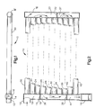
- the heat exchanger assembly is indicated generally at 10 and has an inlet to adapt it for external connection thereto denoted by reference numeral 12 for receiving a flow of pressurized fluid such as refrigerant therein.
- the inlet 12 is connected to one end of a manifold tube 14 which has at the remote end thereof an enlarged portion denoted by reference numeral 16.
- a second manifold tube 15 is disposed in spaced generally parallel arrangement with the manifold 14; and, the manifolds 14 and 15 are interconnected as will hereinafter be described by a plurality of cross tubes.
- the first manifold 14 has a plug or partition 18 disposed therein at a desired distance from the inlet 12 such that a common end of a plurality of cross tubes denoted by reference numerals 20, 22, 24 are in communication with a chamber 19 and the inlet 12; and, the opposite end of the tubes 20, 22, 24 are connected to the upper end of manifold 15.
- a second plurality of manifold tubes denoted by reference numerals 26, 28, 30 have one common end of each connected to the manifold 15 with the opposite end of each tube 26, 28,30 connected to chamber 39 in manifold 14 on the side of plug 18 opposite the tubes 20, 22, 24.
- a second partition or plug 32 is provided in the manifold 15 to isolate to form a common chamber 33 in the manifold communicating with the tubes 20-30.
- a third plug or partition denoted by reference numeral 38 is provided in manifold 14 to form the chamber 39.
- a plurality of tubes denoted by reference numerals 40, 42 has one common end of each connected to manifold 14 below plug 38 to communicate with the outlet chamber 44, with the opposite end of the tubes 40, 42 connected to manifold 15 to communicate with the chamber 37.
- flow entering chamber 37 from tubes 34, 36 returns to manifold 14 in chamber 44 via tubes 40, 42 and from chamber 44 flows to the outlet 16.
- the enlarged end portion 16 of the manifold 14 has received therein a filter/drier cartridge indicated generally at 46 which is formed of a header 48 having an outlet passage 50 formed therein with a basket or shell 52 having the rim of the open end thereof attached to the header 50.
- the header 50 has a reduced diameter portion 54 which is undercut at 56 such that the end of the basket 52 is deformed such as by crimping thereover and is thus retained thereon.
- the end of the basket 52 remote from header 48 is perforated to form apertures 57 preferably by punching out tabs as denoted by reference numeral 58.
- the basket 52 is filled with a suitable desiccant material indicated by reference numeral 60 which is preferably of a granular form.
- a perforated metal cup 62 having a plurality of apertures 61 is pressed into the end of the shell 52 and forms a plenum chamber 63 between the desiccant material and header outlet.
- a layer of suitable filter material such as for example fibrous glass material is disposed adjacent the inner surface of the perforated end of the cup 52 and also adjacent the perforations in the cup 62 in the interior of the basket 52.
- the header is peripherally welded to the enlarged diameter portion 16 of the manifold 14 as indicated by reference numeral 64 to seal and retain the header to the outlet portion 16 of manifold tube 14.
- FIG. 4 an alternate embodiment of the invention is illustrated as having a tubular heat exchanger manifold 114 having an enlarged outlet end 116 with a filter/drier cartridge denoted generally at 146 received therein.
- the cartridge 146 has a basket or shell 152 with perforations 157 in one end and attached by the deforming the rim thereof 156 over an undercut 154 provided in a header 148 having outlet port 150.
- the basket is filled with desiccant material 160; and, the header 148 has a resilient seal ring received in an annular groove 172.
- the end of the enlarged tubular portion 116 of manifold 114 is deformed over a chamfered surface 174 provided on the header to retain the header and cartridge in the outlet formed by the enlarged portion 116.
- the present invention thus provides a novel heat exchanger particularly suitable for the refrigerant condenser employed in automotive air conditioning applications and has a cartridge type filter/drier assembled integrally into the construction of the heat exchanger.
Landscapes
- Engineering & Computer Science (AREA)
- Physics & Mathematics (AREA)
- Mechanical Engineering (AREA)
- Thermal Sciences (AREA)
- General Engineering & Computer Science (AREA)
- Chemical & Material Sciences (AREA)
- Analytical Chemistry (AREA)
- Power Engineering (AREA)
- Air-Conditioning For Vehicles (AREA)
- Heat-Exchange Devices With Radiators And Conduit Assemblies (AREA)
- Drying Of Gases (AREA)
Claims (8)
- Un échangeur de chaleur exothermique (10) pour un système de réfrigération comprenant :(a) une pluralité de conduits (20, 22, 24, 26, 30, 34, 36, 40, 42) disposés dans un agencement sensiblement parallèle;(b) un premier (14) et un second collecteur (15), chacun disposé pour interconnecter les mêmes extrémités desdits conduits afin de permettre un écoulement entre eux;(c) une partie d'extrémité de sortie de plus grand diamètre (16) formée dans l'un desdits premier (14) et second (15) collecteurs;(d) délimitant intérieurement une cavité de réception de cartouche qui en fait partie intégrante; et(e) un ensemble de cartouche (46) comprenant :(i) un culot (48) en contact étanche avec ladite partie d'extrémité de sortie (16) et comportant un orifice de sortie agencé pour pouvoir être raccordé à un conduit externe et un panier (52) reçu dans ladite cavité dont le rebord est fixé audit bouchon de sortie (48) et dont l'extrémité éloignée est perforée;(ii) une matière déshydratante (60) disposée à l'intérieur dudit panier (52);(iii) des moyens d'étanchéité (64, 170) servant à adapter de manière étanche ledit culot (48) dans ladite partie d'extrémité de sortie (16).
- L'échangeur de chaleur défini dans la revendication 1, dans lequel ledit sous-ensemble de cartouche (46) comporte des moyens formant plaque perforée (62) disposés dans ledit panier (52) et délimitant une chambre de tranquilisation (63) entre ladite matière déshydratante granulaire (60) et le dit orifice de sortie (50) dudit culot.
- L'échangeur de chaleur défini dans la revendication 1, dans lequel ledit sous-ensemble de cartouche (46) comporte des moyens formant plaque perforée (62) disposés dans ledit panier (52) et délimitant une chambre de tranquilisation (63) entre ladite matière déshydratante granulaire (60) et le dit orifice de sortie (50) dudit collecteur et une couche de matière filtrante fibreuse (67) disposée entre ladite culot déshydratante granulaire (60) et ladite plaque perforée.
- L'échangeur de chaleur défini dans l'une quelconque des revendications 1 à 3, dans lequel ledit ensemble de cartouche (46) est retenu dans ladite partie d'extrémité de sortie (16) par déformation de ladite partie d'extrémité de sortie tubulaire autour dudit culot.
- L'échangeur de chaleur défini dans l'une quelconque des revendications 1 à 3, dans lequel ledit ensemble de cartouche (46) est retenu dans ladite partie d'extrémité de sortie (16) par soudage sur ledit culot (48).
- L'échangeur de chaleur défini dans la revendication 2, comportant, en outre, une couche de matière filtrante (67) adjacente auxdits moyens formant plaque perforée (62).
- L'échangeur de chaleur défini dans l'une quelconque des revendications 1 à 6, comprenant, en outre, une couche de matière filtrante (65) adjacente à ladite extrémité perforée dudit panier (52).
- L'échangeur de chaleur défini dans l'une quelconque des revendications 1 à 7, dans lequel lesdits moyens d'étanchéité servant à retenir et à assurer l'étanchéité comprennent une bague d'étanchéité élastique (170) et la déformation de ladite partie d'extrémité de sortie (16) de plus grand diamètre.
Applications Claiming Priority (2)
| Application Number | Priority Date | Filing Date | Title |
|---|---|---|---|
| US315044 | 1994-09-29 | ||
| US08/315,044 US5487279A (en) | 1994-09-29 | 1994-09-29 | Heat exchanger with integral filter/drier cartridge |
Publications (2)
| Publication Number | Publication Date |
|---|---|
| EP0704662A1 EP0704662A1 (fr) | 1996-04-03 |
| EP0704662B1 true EP0704662B1 (fr) | 2000-03-15 |
Family
ID=23222630
Family Applications (1)
| Application Number | Title | Priority Date | Filing Date |
|---|---|---|---|
| EP95115480A Expired - Lifetime EP0704662B1 (fr) | 1994-09-29 | 1995-09-29 | Echangeur de chaleur à cartouche de filtre déshydrateur intégrale |
Country Status (5)
| Country | Link |
|---|---|
| US (1) | US5487279A (fr) |
| EP (1) | EP0704662B1 (fr) |
| JP (1) | JPH08261602A (fr) |
| CA (1) | CA2159143C (fr) |
| DE (1) | DE69515585T2 (fr) |
Cited By (1)
| Publication number | Priority date | Publication date | Assignee | Title |
|---|---|---|---|---|
| US7784302B2 (en) | 2002-03-25 | 2010-08-31 | Behr France Hambach S.A.R.L. | Soldered refrigerant condenser |
Families Citing this family (17)
| Publication number | Priority date | Publication date | Assignee | Title |
|---|---|---|---|---|
| DE19800739B4 (de) * | 1997-01-31 | 2009-04-09 | Volkswagen Ag | Klimaanlage |
| DE19712714A1 (de) * | 1997-03-26 | 1998-10-01 | Behr Gmbh & Co | Einsatz für ein Sammlerprofil eines Kondensators |
| GB2326933A (en) * | 1997-07-02 | 1999-01-06 | Ford Motor Co | Condenser end cap with charge port |
| US5755113A (en) * | 1997-07-03 | 1998-05-26 | Ford Motor Company | Heat exchanger with receiver dryer |
| JP4109764B2 (ja) * | 1998-09-02 | 2008-07-02 | 昭和電工株式会社 | サブクールシステムコンデンサ |
| JP3897211B2 (ja) * | 1998-09-22 | 2007-03-22 | 日本軽金属株式会社 | 受液器 |
| JP3959702B2 (ja) * | 1999-09-10 | 2007-08-15 | 日本軽金属株式会社 | 受液器 |
| US6446463B2 (en) * | 2000-03-09 | 2002-09-10 | S.K.G. Italiana S.P.A. | Filter cartridge and condenser |
| EP1249672A3 (fr) * | 2001-04-10 | 2004-07-07 | Sanden Corporation | Condenseur à passage multiple et à sous-refroidissement |
| DE10135731A1 (de) * | 2001-07-21 | 2003-02-06 | Volkswagen Ag | Vorrichtung zur Kühlung der Fahrgastzelle eines Automobils |
| DE10164668A1 (de) * | 2001-12-28 | 2003-07-10 | Behr Lorraine S A R L Europole | Gelöteter Kondensator |
| US20060070724A1 (en) * | 2004-10-06 | 2006-04-06 | Visteon Global Technologies, Inc. | Integrated receiver dryer sleeve |
| FR2879166B1 (fr) * | 2004-12-09 | 2007-02-16 | Valeo Thermique Moteur Sas | Reservoir de fluide a paroi tubulaire, en particulier pour condenseur de climatisation. |
| WO2008141626A1 (fr) * | 2007-05-22 | 2008-11-27 | Institut Für Luft- Und Kältetechnik Gemeinnützige Gmbh | Condenseur de paroi arrière de réfrigérateurs de ménage |
| US20150041414A1 (en) * | 2013-08-09 | 2015-02-12 | Ledwell & Son Enterprises, Inc. | Hydraulic fluid cooler and filter |
| CN108168149B (zh) * | 2017-03-03 | 2020-07-10 | 泉州台商投资区国钗商贸有限公司 | 一种电动汽车 |
| CN110822776B (zh) * | 2019-07-22 | 2021-07-27 | 北京市京科伦冷冻设备有限公司 | 一种多级压差经济器和二氧化碳制冷系统及降温方法 |
Family Cites Families (16)
| Publication number | Priority date | Publication date | Assignee | Title |
|---|---|---|---|---|
| US2260608A (en) * | 1940-03-14 | 1941-10-28 | Crosley Corp | Method of dehydrating refrigeration units |
| US2658359A (en) * | 1949-02-17 | 1953-11-10 | Artkraft Mfg Corp | Evaporator |
| US2645099A (en) * | 1950-09-29 | 1953-07-14 | Bailey Perkins Inc | Capillary tube assembly for refrigerators |
| FR1077969A (fr) * | 1953-06-01 | 1954-11-15 | Capsule pour déshydrateur d'appareil frigorifique et déshydrateur obtenu avec cette capsule | |
| US3149479A (en) * | 1961-05-01 | 1964-09-22 | Rudy Mfg Company | Evaporator-condenser unit |
| US3443367A (en) * | 1967-03-10 | 1969-05-13 | Edward W Bottum | Suction accumulator |
| US3680707A (en) * | 1971-07-30 | 1972-08-01 | Virginia Chemicals Inc | Filter drier |
| JPS4943334A (fr) * | 1972-09-01 | 1974-04-24 | ||
| US4637881A (en) * | 1983-03-30 | 1987-01-20 | Emerson Electric Co. | Filter drier |
| JP3081941B2 (ja) * | 1990-08-23 | 2000-08-28 | 株式会社ゼクセル | レシーバタンク一体型コンデンサ |
| DE4035071A1 (de) * | 1990-11-05 | 1992-05-07 | Hansa Metallwerke Ag | Filtertrockner sowie austauschbarer einsatz fuer diesen |
| US5146767A (en) * | 1991-05-13 | 1992-09-15 | General Motors Corporation | Condenser with dehydrator subcooler |
| US5245842A (en) * | 1992-05-01 | 1993-09-21 | Fayette Tubular Technology Corporation | Receiver dryer |
| JP3326537B2 (ja) * | 1992-09-10 | 2002-09-24 | 株式会社ゼクセルヴァレオクライメートコントロール | レシーバタンク一体型コンデンサ |
| US5289697A (en) * | 1992-10-28 | 1994-03-01 | Eaton Corporation | Refrigerant receiver/drier |
| DE4245046C8 (de) * | 1992-11-18 | 2008-08-21 | Behr Gmbh & Co. Kg | Kondensator für eine Klimaanlage eines Fahrzeuges |
-
1994
- 1994-09-29 US US08/315,044 patent/US5487279A/en not_active Expired - Fee Related
-
1995
- 1995-09-25 JP JP7270510A patent/JPH08261602A/ja active Pending
- 1995-09-26 CA CA002159143A patent/CA2159143C/fr not_active Expired - Fee Related
- 1995-09-29 DE DE69515585T patent/DE69515585T2/de not_active Expired - Fee Related
- 1995-09-29 EP EP95115480A patent/EP0704662B1/fr not_active Expired - Lifetime
Cited By (1)
| Publication number | Priority date | Publication date | Assignee | Title |
|---|---|---|---|---|
| US7784302B2 (en) | 2002-03-25 | 2010-08-31 | Behr France Hambach S.A.R.L. | Soldered refrigerant condenser |
Also Published As
| Publication number | Publication date |
|---|---|
| CA2159143A1 (fr) | 1996-03-30 |
| DE69515585T2 (de) | 2000-11-02 |
| US5487279A (en) | 1996-01-30 |
| CA2159143C (fr) | 2000-03-21 |
| EP0704662A1 (fr) | 1996-04-03 |
| JPH08261602A (ja) | 1996-10-11 |
| DE69515585D1 (de) | 2000-04-20 |
Similar Documents
| Publication | Publication Date | Title |
|---|---|---|
| US5487279A (en) | Heat exchanger with integral filter/drier cartridge | |
| US6044900A (en) | Heat exchanger with a receiver | |
| US5088294A (en) | Condenser with a built-in receiver | |
| US5479985A (en) | Heat exchanger | |
| JP3629819B2 (ja) | 受液器一体型凝縮器 | |
| US5813249A (en) | Refrigeration cycle | |
| US5152339A (en) | Manifold assembly for a parallel flow heat exchanger | |
| US6185959B1 (en) | Refrigerant system components with cartridge type thermal expansion valve and method of making same | |
| JP3925158B2 (ja) | 冷媒凝縮器 | |
| US5289697A (en) | Refrigerant receiver/drier | |
| EP1363086B1 (fr) | Echangeur de chaleur avec une partie pour contenir une pièce rapportée laquelle y est supportée élastiquement | |
| US5097900A (en) | Condenser having partitions for changing the refrigerant flow direction | |
| JPS603433Y2 (ja) | 冷媒アキユムレ−タ | |
| JP2824629B2 (ja) | 空調システム用アキュムレータ | |
| US5911879A (en) | Refrigerant filter/drier | |
| CN100373114C (zh) | 制冷系统及其冷凝装置 | |
| JPH0875317A (ja) | 受液器付コンデンサ | |
| US3858406A (en) | Refrigerant evaporator for air conditioner | |
| US7024884B2 (en) | Condenser for an air conditioning system | |
| US5787573A (en) | Method of making air conditioner receiver dryer | |
| US5425250A (en) | Receiver/dryer | |
| KR20030056587A (ko) | 일체형의 수액기를 가지는 열교환기와 이의 제조방법 | |
| JPH09264637A (ja) | レシーバ付き熱交換器 | |
| US20240230186A9 (en) | Fluid collector | |
| JPH09222267A (ja) | レシーバ一体型熱交換器 |
Legal Events
| Date | Code | Title | Description |
|---|---|---|---|
| PUAI | Public reference made under article 153(3) epc to a published international application that has entered the european phase |
Free format text: ORIGINAL CODE: 0009012 |
|
| AK | Designated contracting states |
Kind code of ref document: A1 Designated state(s): DE FR |
|
| 17P | Request for examination filed |
Effective date: 19960924 |
|
| 17Q | First examination report despatched |
Effective date: 19980116 |
|
| GRAG | Despatch of communication of intention to grant |
Free format text: ORIGINAL CODE: EPIDOS AGRA |
|
| GRAG | Despatch of communication of intention to grant |
Free format text: ORIGINAL CODE: EPIDOS AGRA |
|
| GRAH | Despatch of communication of intention to grant a patent |
Free format text: ORIGINAL CODE: EPIDOS IGRA |
|
| GRAH | Despatch of communication of intention to grant a patent |
Free format text: ORIGINAL CODE: EPIDOS IGRA |
|
| GRAA | (expected) grant |
Free format text: ORIGINAL CODE: 0009210 |
|
| AK | Designated contracting states |
Kind code of ref document: B1 Designated state(s): DE FR |
|
| REF | Corresponds to: |
Ref document number: 69515585 Country of ref document: DE Date of ref document: 20000420 |
|
| ET | Fr: translation filed | ||
| PLBE | No opposition filed within time limit |
Free format text: ORIGINAL CODE: 0009261 |
|
| STAA | Information on the status of an ep patent application or granted ep patent |
Free format text: STATUS: NO OPPOSITION FILED WITHIN TIME LIMIT |
|
| 26N | No opposition filed | ||
| PGFP | Annual fee paid to national office [announced via postgrant information from national office to epo] |
Ref country code: FR Payment date: 20020903 Year of fee payment: 8 |
|
| PGFP | Annual fee paid to national office [announced via postgrant information from national office to epo] |
Ref country code: DE Payment date: 20020930 Year of fee payment: 8 |
|
| PG25 | Lapsed in a contracting state [announced via postgrant information from national office to epo] |
Ref country code: DE Free format text: LAPSE BECAUSE OF NON-PAYMENT OF DUE FEES Effective date: 20040401 |
|
| PG25 | Lapsed in a contracting state [announced via postgrant information from national office to epo] |
Ref country code: FR Free format text: LAPSE BECAUSE OF NON-PAYMENT OF DUE FEES Effective date: 20040528 |
|
| REG | Reference to a national code |
Ref country code: FR Ref legal event code: ST |