EP0704700A1 - Transducteur d'essai ultrasonore des roues de chemin de fer - Google Patents
Transducteur d'essai ultrasonore des roues de chemin de fer Download PDFInfo
- Publication number
- EP0704700A1 EP0704700A1 EP95112909A EP95112909A EP0704700A1 EP 0704700 A1 EP0704700 A1 EP 0704700A1 EP 95112909 A EP95112909 A EP 95112909A EP 95112909 A EP95112909 A EP 95112909A EP 0704700 A1 EP0704700 A1 EP 0704700A1
- Authority
- EP
- European Patent Office
- Prior art keywords
- receiving device
- ultrasonic
- transmitter
- center line
- receiver
- Prior art date
- Legal status (The legal status is an assumption and is not a legal conclusion. Google has not performed a legal analysis and makes no representation as to the accuracy of the status listed.)
- Granted
Links
Images
Classifications
-
- G—PHYSICS
- G01—MEASURING; TESTING
- G01M—TESTING STATIC OR DYNAMIC BALANCE OF MACHINES OR STRUCTURES; TESTING OF STRUCTURES OR APPARATUS, NOT OTHERWISE PROVIDED FOR
- G01M17/00—Testing of vehicles
- G01M17/08—Railway vehicles
- G01M17/10—Suspensions, axles or wheels
-
- G—PHYSICS
- G01—MEASURING; TESTING
- G01N—INVESTIGATING OR ANALYSING MATERIALS BY DETERMINING THEIR CHEMICAL OR PHYSICAL PROPERTIES
- G01N2291/00—Indexing codes associated with group G01N29/00
- G01N2291/10—Number of transducers
- G01N2291/102—Number of transducers one emitter, one receiver
-
- G—PHYSICS
- G01—MEASURING; TESTING
- G01N—INVESTIGATING OR ANALYSING MATERIALS BY DETERMINING THEIR CHEMICAL OR PHYSICAL PROPERTIES
- G01N2291/00—Indexing codes associated with group G01N29/00
- G01N2291/26—Scanned objects
- G01N2291/269—Various geometry objects
- G01N2291/2696—Wheels, Gears, Bearings
Definitions
- the invention relates to an ultrasonic transducer for testing railroad wheels for cracks and the like.
- the transmission of the ultrasonic signals to the railroad wheel to be tested and the retransmission from the railroad wheel to the Receiving device is contactless and / or touching.
- Ultrasonic transducers of the type described at the outset are known and are used for the economic inspection of railway wheels in the installed state, the train traveling slowly over a test route which is provided with such ultrasonic transducers.
- ultrasonic transducers in which the ultrasonic signals are generated with piezo elements and transmitted to the wheel set via a fluid, which results in the serious disadvantage of frequent destruction of the bubble containing the coupling fluid, there are also ultrasonic transducers in which the ultrasonic vibrations contact the railroad wheel without contact be transmitted.
- the latter ultrasonic transducers are mostly based on an electrodynamic process, in which two pulse packets are always generated when the ultrasonic pulse is generated in the railroad wheel, and these run around the wheel in opposite directions.
- both pulse packets take the same time to revolve around the wheel (both pulses cover exactly the same distance with the length of the wheel circumference), both packets (the right-handed and the left-handed pulse) meet at the exact location where the ultrasonic waves were generated .
- the Ultrasonic pulses are generated by means of a transmitting device which is arranged in a test head, and the associated echo signals are recorded by means of a receiving device, this receiving device being arranged directly next to the transmitting device or being integrated therein. Due to the two pulse packets revolving in opposite directions, the two pulse packets now overlap in an area around the location of the pulse generation, ie the transmitting device.
- the two pulse packets which are sections of wave trains, overlap in such a way that wave crest meets wave crest, so that there is a doubling of the Amplitude is coming.
- a wave crest always meets a wave trough, so that the overlapping impulse packets are locally extinguished. All intermediate forms are also possible.
- the invention is therefore based on the object of improving the detection of cracks by means of such ultrasound transducers and of making the diagnosis more reliable.
- this object is achieved in that the transmitting device and the receiving device are arranged so far apart from each other in the circumferential direction of the railway wheel that the receiving device lies outside a region of the superposition of oppositely rotating pulse packets of the ultrasonic signals which is symmetrical with the center line of the transmitting device.
- the receiving device consequently receives the pulse packet revolving in one direction and then the pulse packet revolving in the opposite direction at different times.
- the shape of the circulating signal received is now directly related to any cracks in the railroad wheel set and can therefore be used as a reliable assessment parameter for the quality of the wheel set being tested without any interference caused by superimposition affecting the reliability of the analysis .
- the receiving device is arranged in the next possible position in relation to the transmitting device, so that just no signal can be received, which arises from the superimposition of the left and right-handed ultrasonic pulse.
- This minimization of the distance is very advantageous insofar as the length of the path within which no statement can be made about the possible presence of cracks is very limited.
- the minimization of the distance between the transmitting and receiving device in the above. Way also has the advantage that the space required for the ultrasonic transducer can be kept small.
- the transmitting device and the receiving coil are arranged in a common test head.
- the sending and receiving device always have the equidistant from each other, which guarantees that the right and left-hand pulse packets do not overlap. Due to the common arrangement in a test head, the possibility of synchronously feeding both coils to the railway wheel to be tested is considerably facilitated and the set-up time during the test is shortened.
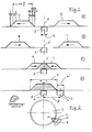
- Fig. 1a it can be seen how the pulse packets L and R generated by the transmission device 2 move in the opposite direction away from the transmission device in the circumferential direction through the railway wheel.
- the scope of the railway wheel is shown as a settlement. Because of their simultaneous generation and their identical speed, namely the speed of sound c in the railway wheel, both pulse packets L and R are always at the same distance from the center line 6 of the transmitter device 2.
- the ultrasound pulse packets L and R are generated over the width b of the transmitter device, the energy of the impulse over this Length b increases from zero to its final value.
- Fig. 1b now shows how the two pulse packets R and L are after their encounter (not shown) at the diametrically opposite point of the wheel of the transmitter on the way back to the transmitter.
- the sides and the directions on their return to the transmitting device 2 are exchanged in comparison to the position according to FIG.
- the distance between the two pulse packets R and L from the center line 6 of the transmitting device is still identical, since the two pulse packets have traveled the same path due to their identical speed.
- FIG. 1c shows a situation in which the two oppositely rotating pulse packs R and L have already overlapped to a certain extent. This area is shown hatched. The hatched overlay area is symmetrical to the center line 6 of the transmission device.
- 1d shows the position in which the two pulse packets R and L lie exactly congruent with one another, as was also the case at the time of their creation.
- the length of area 4 results from the sum of twice the width b of the transmitting device and the length c ⁇ n ⁇ 1 / f the area in which the energy of the pulse packet is kept constant.
- the area 4 lies symmetrically to the center line 6 of the transmitting device 2 and characterizes the maximum extent of the area of the superimposition of the oppositely rotating pulse packets L and R. Outside of this area 4 there are no overlaps of the opposing pulse packets R and L, so that there is a temporally successive, separate evaluation of the echo signals is possible.
- the largest possible distance from a point at which overlaps can still occur is therefore b + 1/2 ⁇ c ⁇ n ⁇ 1 / f measured on both sides from the center line 6 of the transmission device.
- 1d also shows a receiving device 3 which has the width b '.
- This is the minimum distance between the center lines in order to arrange the receiving device 3 with its entire width b 'in such a way that it does not fall in the region 4 of the superimpositions of the opposite pulse pacts R and L. Minimizing this distance A according to the formula just mentioned is advantageous because the space for the ultrasonic transducer is thus kept as small as possible.
- a test head 5 in which both the transmitting device 2 and the receiving device 3 are arranged, is arranged on the tread of a wheel 1 to be checked for cracks.
- a minimized distance A between the transmitting and receiving device the dimensions of the test head can be kept small, which makes it more manageable and more accessible to the wheel with limited space facilitated.
Landscapes
- Physics & Mathematics (AREA)
- General Physics & Mathematics (AREA)
- Investigating Or Analyzing Materials By The Use Of Ultrasonic Waves (AREA)
Applications Claiming Priority (2)
| Application Number | Priority Date | Filing Date | Title |
|---|---|---|---|
| DE9415885U DE9415885U1 (de) | 1994-10-01 | 1994-10-01 | Ultraschallwandler zur Prüfung von Eisenbahnrädern |
| DE9415885U | 1994-10-01 |
Publications (2)
| Publication Number | Publication Date |
|---|---|
| EP0704700A1 true EP0704700A1 (fr) | 1996-04-03 |
| EP0704700B1 EP0704700B1 (fr) | 1999-11-03 |
Family
ID=6914402
Family Applications (1)
| Application Number | Title | Priority Date | Filing Date |
|---|---|---|---|
| EP95112909A Expired - Lifetime EP0704700B1 (fr) | 1994-10-01 | 1995-08-17 | Transducteur d'essai ultrasonore des roues de chemin de fer |
Country Status (5)
| Country | Link |
|---|---|
| US (1) | US5654510A (fr) |
| EP (1) | EP0704700B1 (fr) |
| DE (2) | DE9415885U1 (fr) |
| DK (1) | DK0704700T3 (fr) |
| ES (1) | ES2137422T3 (fr) |
Cited By (1)
| Publication number | Priority date | Publication date | Assignee | Title |
|---|---|---|---|---|
| DE19943215A1 (de) * | 1999-09-09 | 2001-04-12 | Siemens Ag | Verfahren und Vorrichtung zur Detektion eines Fehlers mittels Ultraschall |
Families Citing this family (10)
| Publication number | Priority date | Publication date | Assignee | Title |
|---|---|---|---|---|
| US6698279B1 (en) * | 1996-10-23 | 2004-03-02 | Ultrasonics And Magnetics Corporation | Method and apparatus for testing the integrity of railroad locomotive wheels and railroad car wheels |
| WO2000005576A2 (fr) * | 1998-07-23 | 2000-02-03 | Siemens Aktiengesellschaft | Procede et dispositifs pour detecter d'une fissure dans une roue de chemin de fer |
| ES2151832B1 (es) * | 1998-08-04 | 2001-07-16 | Talgo Patentes | Instalacion para la evaluacion automatica del estado de la banda de rodadura en ruedas de trenes en movimiento. |
| DE29914616U1 (de) * | 1999-08-20 | 2000-01-13 | Siemens AG, 80333 München | Prüfeinrichtung für Schienenräder |
| GB2440959B (en) * | 2006-08-15 | 2008-10-08 | Rolls Royce Plc | A method of inspecting a component and an apparatus for inspecting a component |
| DE102006052535B3 (de) * | 2006-11-06 | 2008-05-15 | Db Fernverkehr Ag | Verfahren zur Ermittlung des Zustandes von Oberflächenschäden in Radlaufflächen von Schienenfahrzeugen |
| US7716010B2 (en) * | 2008-01-24 | 2010-05-11 | General Electric Company | System, method and kit for measuring a distance within a railroad system |
| US7882742B1 (en) * | 2008-10-28 | 2011-02-08 | Herzog Services, Inc. | Apparatus for detecting, identifying and recording the location of defects in a railway rail |
| DE102012207427A1 (de) | 2012-05-04 | 2013-11-07 | Fraunhofer-Gesellschaft zur Förderung der angewandten Forschung e.V. | Verfahren zur optisch-abtastenden Prüfung einer Radlauffläche eines Rades eines Zuges im Fahrbetrieb, optische Prüfvorrichtung, Prüfsystem und Prüfsystemanordnung sowie Steuermodul |
| DE102018202757A1 (de) * | 2018-02-23 | 2019-08-29 | Siemens Aktiengesellschaft | Verfahren und Vorrichtung zur zerstörungsfreien Prüfung eines Bauteils |
Citations (4)
| Publication number | Priority date | Publication date | Assignee | Title |
|---|---|---|---|---|
| US3812708A (en) * | 1971-11-17 | 1974-05-28 | Scanning Sys Inc | Method and apparatus for testing wheels and defect detection in wheels |
| DE3218453A1 (de) * | 1982-05-15 | 1983-11-17 | Fraunhofer-Gesellschaft zur Förderung der angewandten Forschung e.V., 8000 München | Verfahren, anordnung und schaltung zur zerstoerungsfreien pruefung der laufflaeche von eisenbahnraedern mittels ultraschall-oberflaechenwellen |
| DE3834828C1 (fr) * | 1988-10-13 | 1990-03-22 | Fraunhofer-Gesellschaft Zur Foerderung Der Angewandten Forschung Ev, 8000 Muenchen, De | |
| DE3943226A1 (de) * | 1989-01-13 | 1990-07-19 | Mannesmann Ag | Verfahren und vorrichtung zur erfassung von ungaenzen an langgestreckten werkstuecken |
Family Cites Families (3)
| Publication number | Priority date | Publication date | Assignee | Title |
|---|---|---|---|---|
| US4435984A (en) * | 1980-04-21 | 1984-03-13 | Southwest Research Institute | Ultrasonic multiple-beam technique for detecting cracks in bimetallic or coarse-grained materials |
| US4651568A (en) * | 1984-08-30 | 1987-03-24 | Kirin Beer Kabushiki Kaisha | Glass bottle inspection |
| ES2088409T3 (es) * | 1989-01-13 | 1996-08-16 | Mannesmann Ag | Procedimiento para la deteccion de deficiencias en piezas de trabajo oblongas. |
-
1994
- 1994-10-01 DE DE9415885U patent/DE9415885U1/de not_active Expired - Lifetime
-
1995
- 1995-08-17 DK DK95112909T patent/DK0704700T3/da active
- 1995-08-17 ES ES95112909T patent/ES2137422T3/es not_active Expired - Lifetime
- 1995-08-17 DE DE59507174T patent/DE59507174D1/de not_active Expired - Fee Related
- 1995-08-17 EP EP95112909A patent/EP0704700B1/fr not_active Expired - Lifetime
- 1995-09-28 US US08/535,557 patent/US5654510A/en not_active Expired - Fee Related
Patent Citations (4)
| Publication number | Priority date | Publication date | Assignee | Title |
|---|---|---|---|---|
| US3812708A (en) * | 1971-11-17 | 1974-05-28 | Scanning Sys Inc | Method and apparatus for testing wheels and defect detection in wheels |
| DE3218453A1 (de) * | 1982-05-15 | 1983-11-17 | Fraunhofer-Gesellschaft zur Förderung der angewandten Forschung e.V., 8000 München | Verfahren, anordnung und schaltung zur zerstoerungsfreien pruefung der laufflaeche von eisenbahnraedern mittels ultraschall-oberflaechenwellen |
| DE3834828C1 (fr) * | 1988-10-13 | 1990-03-22 | Fraunhofer-Gesellschaft Zur Foerderung Der Angewandten Forschung Ev, 8000 Muenchen, De | |
| DE3943226A1 (de) * | 1989-01-13 | 1990-07-19 | Mannesmann Ag | Verfahren und vorrichtung zur erfassung von ungaenzen an langgestreckten werkstuecken |
Cited By (2)
| Publication number | Priority date | Publication date | Assignee | Title |
|---|---|---|---|---|
| DE19943215A1 (de) * | 1999-09-09 | 2001-04-12 | Siemens Ag | Verfahren und Vorrichtung zur Detektion eines Fehlers mittels Ultraschall |
| DE19943215C2 (de) * | 1999-09-09 | 2001-07-19 | Siemens Ag | Verfahren und Vorrichtung zur Detektion eines Fehlers mittels Ultraschall |
Also Published As
| Publication number | Publication date |
|---|---|
| DK0704700T3 (da) | 2000-03-06 |
| DE59507174D1 (de) | 1999-12-09 |
| DE9415885U1 (de) | 1994-12-15 |
| US5654510A (en) | 1997-08-05 |
| EP0704700B1 (fr) | 1999-11-03 |
| ES2137422T3 (es) | 1999-12-16 |
Similar Documents
| Publication | Publication Date | Title |
|---|---|---|
| DE4424555C2 (de) | Verfahren zum Erfassen von Korrosionsermüdungsrissen in Membrankesselrohren | |
| EP0704700B1 (fr) | Transducteur d'essai ultrasonore des roues de chemin de fer | |
| DE2632694A1 (de) | Verfahren und einrichtung zum anregen und empfang von ultraschallnormalwellen | |
| DE4311963A1 (de) | Füllstandsmeßgerät | |
| DE102019106427B4 (de) | Wandler und Wandleranordnung für Ultraschall-Prüfkopfsysteme, Ultraschall-Prüfkopfsystem und Prüfverfahren | |
| DE3787825T2 (de) | Verfahren zur Messung von Restspannungen im Stoff eines Prüfobjektes. | |
| EP1359413A2 (fr) | Procédé pour détecter des défauts dans des pièces oblongues avec des ultrasons | |
| DE3218453C2 (de) | Elektromagnetischer Ultraschallwandler zur zerstörungsfreien Prüfung von elektrisch leitfähigen Werkstoffen | |
| DE3308637A1 (de) | Ultraschallgeraet | |
| EP3894799B1 (fr) | Agencement de transducteurs ultrasonores d'un appareil de mesure de debit a ultrasons a pinces, et appareil de mesure de debit a ultrasons a pinces et procede de mise en marche de l'appareil de mesure de debit a ultrasons a pinces | |
| EP3867636B1 (fr) | Procédé et dispositif de détermination non invasive de caractéristiques d'un courant polyphasé | |
| DE3414362A1 (de) | Verfahren zur ultraschall-pruefung von bolzen mit einem wanddickensprung | |
| EP0116901A2 (fr) | Appareil de contrôle ultrasonore | |
| DE2732090B2 (de) | Einrichtung zur volumetrischen Ultraschall-Prüfung der Wände von Behältern und Rohren | |
| DE19513194C1 (de) | Verfahren und Vorrichtung zur Erfassung von Ungänzen an langgestreckten Werkstücken, insbesondere Rohre und Stangen | |
| EP0086531B1 (fr) | Dispositif pour la recherche par ultrasons | |
| DE2950862C2 (fr) | ||
| DE69106997T2 (de) | Impulsechogerät und Verfahren zum Feststellen von Fehlstellen. | |
| DE19957905B4 (de) | Verfahren und Vorrichtung zur zerstörungsfreien Prüfung von Schweißnähten mittels Ultraschall | |
| DE19832603A1 (de) | Einrichtung zur Zugintegritätskontrolle und/oder Zuglängenmessung | |
| WO2012107218A1 (fr) | Procédé de détection de la position d'un défaut dans un corps | |
| EP0889322A2 (fr) | Procédé de contrÔle non-destructif d'une roue de chemin de fer | |
| DE3943226C2 (de) | Verfahren und Vorrichtung zur Erfassung von Ungänzen an langgestreckten Werkstücken | |
| EP0158929B1 (fr) | Procédé de contrôle ultrasonore de goujons ayant une variation de diamètre | |
| DE2710403C2 (de) | Verfahren und Vorrichtung zur Ultraschallprüfung der Wandstärke von Rohren u.dgl. |
Legal Events
| Date | Code | Title | Description |
|---|---|---|---|
| PUAI | Public reference made under article 153(3) epc to a published international application that has entered the european phase |
Free format text: ORIGINAL CODE: 0009012 |
|
| AK | Designated contracting states |
Kind code of ref document: A1 Designated state(s): DE DK ES FR GB IT |
|
| 17P | Request for examination filed |
Effective date: 19961120 |
|
| 17Q | First examination report despatched |
Effective date: 19970506 |
|
| GRAG | Despatch of communication of intention to grant |
Free format text: ORIGINAL CODE: EPIDOS AGRA |
|
| GRAG | Despatch of communication of intention to grant |
Free format text: ORIGINAL CODE: EPIDOS AGRA |
|
| GRAH | Despatch of communication of intention to grant a patent |
Free format text: ORIGINAL CODE: EPIDOS IGRA |
|
| GRAH | Despatch of communication of intention to grant a patent |
Free format text: ORIGINAL CODE: EPIDOS IGRA |
|
| GRAA | (expected) grant |
Free format text: ORIGINAL CODE: 0009210 |
|
| AK | Designated contracting states |
Kind code of ref document: B1 Designated state(s): DE DK ES FR GB IT |
|
| GBT | Gb: translation of ep patent filed (gb section 77(6)(a)/1977) |
Effective date: 19991103 |
|
| ITF | It: translation for a ep patent filed | ||
| REF | Corresponds to: |
Ref document number: 59507174 Country of ref document: DE Date of ref document: 19991209 |
|
| REG | Reference to a national code |
Ref country code: ES Ref legal event code: FG2A Ref document number: 2137422 Country of ref document: ES Kind code of ref document: T3 |
|
| ET | Fr: translation filed | ||
| REG | Reference to a national code |
Ref country code: DK Ref legal event code: T3 |
|
| PGFP | Annual fee paid to national office [announced via postgrant information from national office to epo] |
Ref country code: GB Payment date: 20000810 Year of fee payment: 6 |
|
| PGFP | Annual fee paid to national office [announced via postgrant information from national office to epo] |
Ref country code: FR Payment date: 20000816 Year of fee payment: 6 |
|
| PGFP | Annual fee paid to national office [announced via postgrant information from national office to epo] |
Ref country code: DK Payment date: 20000817 Year of fee payment: 6 |
|
| PGFP | Annual fee paid to national office [announced via postgrant information from national office to epo] |
Ref country code: ES Payment date: 20000818 Year of fee payment: 6 |
|
| PLBE | No opposition filed within time limit |
Free format text: ORIGINAL CODE: 0009261 |
|
| STAA | Information on the status of an ep patent application or granted ep patent |
Free format text: STATUS: NO OPPOSITION FILED WITHIN TIME LIMIT |
|
| PGFP | Annual fee paid to national office [announced via postgrant information from national office to epo] |
Ref country code: DE Payment date: 20000908 Year of fee payment: 6 |
|
| 26N | No opposition filed | ||
| PG25 | Lapsed in a contracting state [announced via postgrant information from national office to epo] |
Ref country code: GB Free format text: LAPSE BECAUSE OF NON-PAYMENT OF DUE FEES Effective date: 20010817 Ref country code: DK Free format text: LAPSE BECAUSE OF NON-PAYMENT OF DUE FEES Effective date: 20010817 |
|
| PG25 | Lapsed in a contracting state [announced via postgrant information from national office to epo] |
Ref country code: ES Free format text: LAPSE BECAUSE OF NON-PAYMENT OF DUE FEES Effective date: 20010818 |
|
| GBPC | Gb: european patent ceased through non-payment of renewal fee |
Effective date: 20010817 |
|
| REG | Reference to a national code |
Ref country code: DK Ref legal event code: EBP |
|
| PG25 | Lapsed in a contracting state [announced via postgrant information from national office to epo] |
Ref country code: FR Free format text: LAPSE BECAUSE OF NON-PAYMENT OF DUE FEES Effective date: 20020430 |
|
| PG25 | Lapsed in a contracting state [announced via postgrant information from national office to epo] |
Ref country code: DE Free format text: LAPSE BECAUSE OF NON-PAYMENT OF DUE FEES Effective date: 20020501 |
|
| REG | Reference to a national code |
Ref country code: FR Ref legal event code: ST |
|
| REG | Reference to a national code |
Ref country code: ES Ref legal event code: FD2A Effective date: 20020911 |
|
| PG25 | Lapsed in a contracting state [announced via postgrant information from national office to epo] |
Ref country code: IT Free format text: LAPSE BECAUSE OF NON-PAYMENT OF DUE FEES;WARNING: LAPSES OF ITALIAN PATENTS WITH EFFECTIVE DATE BEFORE 2007 MAY HAVE OCCURRED AT ANY TIME BEFORE 2007. THE CORRECT EFFECTIVE DATE MAY BE DIFFERENT FROM THE ONE RECORDED. Effective date: 20050817 |