EP0704705A1 - Verfahren und Vorrichtung zur Minimierung eines Fehlers infolge einer Störbewegung bei der Wiederherstellung der Geschwindigkeit in einem Trägheitsmesssystem - Google Patents
Verfahren und Vorrichtung zur Minimierung eines Fehlers infolge einer Störbewegung bei der Wiederherstellung der Geschwindigkeit in einem Trägheitsmesssystem Download PDFInfo
- Publication number
- EP0704705A1 EP0704705A1 EP95402045A EP95402045A EP0704705A1 EP 0704705 A1 EP0704705 A1 EP 0704705A1 EP 95402045 A EP95402045 A EP 95402045A EP 95402045 A EP95402045 A EP 95402045A EP 0704705 A1 EP0704705 A1 EP 0704705A1
- Authority
- EP
- European Patent Office
- Prior art keywords
- speed
- movement
- restitution
- coefficients
- accelerometric
- Prior art date
- Legal status (The legal status is an assumption and is not a legal conclusion. Google has not performed a legal analysis and makes no representation as to the accuracy of the status listed.)
- Granted
Links
Images

Classifications
-
- G—PHYSICS
- G01—MEASURING; TESTING
- G01C—MEASURING DISTANCES, LEVELS OR BEARINGS; SURVEYING; NAVIGATION; GYROSCOPIC INSTRUMENTS; PHOTOGRAMMETRY OR VIDEOGRAMMETRY
- G01C21/00—Navigation; Navigational instruments not provided for in groups G01C1/00 - G01C19/00
- G01C21/10—Navigation; Navigational instruments not provided for in groups G01C1/00 - G01C19/00 by using measurements of speed or acceleration
- G01C21/12—Navigation; Navigational instruments not provided for in groups G01C1/00 - G01C19/00 by using measurements of speed or acceleration executed aboard the object being navigated; Dead reckoning
- G01C21/16—Navigation; Navigational instruments not provided for in groups G01C1/00 - G01C19/00 by using measurements of speed or acceleration executed aboard the object being navigated; Dead reckoning by integrating acceleration or speed, i.e. inertial navigation
- G01C21/183—Compensation of inertial measurements, e.g. for temperature effects
Definitions
- the present invention relates to a method for minimizing, in a system of inertial measurements with linked components, the error due to any disturbing movement in the restitution of the speed, as well as to a device for implementing this restitution of the minimized error speed.
- the accelerometric measurements relating to said system which is mobile relative to an inertial trihedron are carried out in an accelerometric trihedron which is defined with respect to said system, which is subjected to the movements of the latter and which is therefore mobile relative to said inertial trihedron, and these accelerometric measurements must then be transformed in order to be known in said inertial trihedron.
- the attitude between said mobile trihedron and said fixed trihedron is determined from measured gyrometric data indicating the angular variations per unit of time between the two trihedrons considered.
- this attitude is determined from known algorithms, one of the most used and best suited to this type of calculation is the so-called Miller algorithm, and it is embodied in the form of a calculation means, for example in the form of a transformation matrix or a transformation quaternion.
- document FR-2 552 222 presents two different disturbing movements, namely a cone movement, which is caused by movements of the input axes of gyroscopes used in the system and giving rise to errors in the measurement of angular accelerations, and a sculling movement, according to which linear and angular vibrations at relatively high frequency of a few hundred hertz along two orthogonal axes produce a uniform linear acceleration along the third orthogonal axis.
- the object of the present invention is to remedy these drawbacks. It relates to a method for minimizing, in a system of inertial measurements with linked components, the error due to any disturbing movement in the restitution of the speed, said speed being restored by the implementation of a speed restitution process suitable for this purpose using measured accelerometric and gyrometric data combined with specific coefficients.
- the correction thus defined makes it possible to obtain a particularly precise result and it can be implemented with a reduced calculation cost.
- a speed increment ⁇ is used for the implementation of the speed restitution process.
- the mean value of the speed ⁇ is advantageously calculated.
- V ⁇ avg obtained from the speed increment ⁇ V ⁇ F.
- said mean value of the speed ⁇ V ⁇ moy is calculated over a period 2 ⁇ / ⁇ of said disturbing movement, by the relation:
- the most frequent and penalizing disturbing movement in such an inertial measurement system with linked components is a scull movement consisting of a conical movement and a sinusoidal acceleration along the axis of the conical movement.
- the present invention provides in particular two particularly advantageous preferred solutions.
- This solution has the advantage of requiring for its implementation only a minimum of successive measurements, namely two accelerometric measurements and two gyrometric measurements, and moreover the precision obtained, in the correction of the error due to the movement of disturbing scull
- this second solution has the advantage of being particularly well suited to joint use with the Miller algorithm cited in the preamble and generally used to perform transformation calculations between the mobile trihedron and the fixed trihedron.
- the present invention also relates to a device for minimizing in a system of inertial measurements with components linked to the error due to any disturbing movement in the restitution of the speed, said device allowing the implementation of the restitution of the minimized error speed obtained by the process according to the invention described above.
- Figure 1 schematically illustrates the relationship between an accelerometric trihedron and an inertial trihedron in an inertial measurement system with linked components.
- FIG. 2 schematically shows the usual method of calculating the speed in an inertial measurement system with linked components.
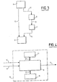
- FIG. 3 schematically illustrates the different steps of the method according to the invention.
- Figure 4 is a block diagram of a device according to the invention.
- the present invention is implemented in an inertial measurement system with linked components, not shown, in which it is sought to know the speed of said system which is mobile relative to a fixed inertial trihedron Tf.
- FIG. 2 schematically illustrates the usual mode for determining the speed in a system of inertial measurements with linked components, implementing a known speed restitution method.
- Said gyrometric measurements ⁇ ⁇ ⁇ are transmitted via a link 3 to a first computer 4 capable of determining a means of calculation, for example a quaternion or a matrix B (t), restoring the attitude of the system and making it possible to pass the mobile repository Tm to the fixed repository Tf.
- a means of calculation for example a quaternion or a matrix B (t)
- said first computer 4 implements a specific algorithm known, preferably the Miller algorithm cited above.
- the present invention provides a method, the steps of which are illustrated diagrammatically in FIG. 3, making it possible to perfect a speed restitution method so as to obtain a particularly effective correction, as well as a correction device 16 shown. in Figure 4, intended to replace the correction device 8 of Figure 2 and allowing the implementation of the results obtained from the method according to the invention.
- ⁇ V ⁇ F B (t) ⁇ V ⁇ eq, in which ⁇ V ⁇ eq represents a speed increment formed, as specified below, from the accelerometric data measured in the mobile accelerometric trihedron Tm, gyrometric data, and specific coefficients, and B (t) a time-dependent attitude matrix t and making it possible to pass from the accelerometric trihedron Tm to the inertial trihedron Tf.
- Said matrix B (t) is calculated in said first computer 4, as mentioned previously, and said speed increment ⁇ V ⁇ eq is formed in the correction device 16.
- the average value of the speed ⁇ is used as the error criterion.
- V ⁇ avg obtained from the speed increment ⁇ V ⁇ F and calculated, for a periodic disturbing movement of pulsation ⁇ , over a period 2 ⁇ / ⁇ of said disturbing movement, by the relation:
- ⁇ V ⁇ F B (h) [ ⁇ V ⁇ j + (ai ⁇ ⁇ ⁇ i + aj ⁇ ⁇ ⁇ j) ⁇ (bi ⁇ V ⁇ i + bj ⁇ V ⁇ j)] ⁇ ⁇ ⁇ j and ⁇ V ⁇ j respectively representing two successive measurements of ⁇ ⁇ ⁇ i and ⁇ V ⁇ i carried out at a time h after the measurements of ⁇ ⁇ ⁇ i and ⁇ V ⁇ i.
- this theoretical form is optimized by looking for the values of ai, aj, bi and bj which limit the error under scull movement.
- ⁇ V ⁇ F B (h) [ ⁇ V ⁇ 1 + ⁇ V ⁇ 2 + ⁇ V ⁇ 3+ (a1 ⁇ ⁇ ⁇ 1 + a2 ⁇ ⁇ ⁇ 2 + a3 ⁇ ⁇ ⁇ 3) ⁇ (b1 ⁇ V ⁇ 1 + b2 ⁇ V ⁇ 2 + b3 ⁇ V ⁇ 3)] ⁇ V ⁇ 1 and ⁇ ⁇ ⁇ 1, ⁇ V ⁇ 2 and ⁇ ⁇ ⁇ 2, ⁇ V ⁇ 3 and ⁇ ⁇ ⁇ ⁇ 3 corresponding in this case to measurements made at instants t1 + h / 3, t1 + (2h) / 3, t1 + h, t1 being any instant.
- said solution is particularly well suited to joint use with the Miller algorithm cited above and generally used to perform the transformation calculations between the mobile trihedron Tm and the fixed trihedron Tf.
- the present invention also relates to a correction device 16 intended to replace the device 8 of FIG. 2 and making it possible in particular to implement the results obtained in the two above-mentioned examples.
Landscapes
- Engineering & Computer Science (AREA)
- Radar, Positioning & Navigation (AREA)
- Remote Sensing (AREA)
- Automation & Control Theory (AREA)
- Physics & Mathematics (AREA)
- General Physics & Mathematics (AREA)
- Gyroscopes (AREA)
- Navigation (AREA)
Applications Claiming Priority (2)
| Application Number | Priority Date | Filing Date | Title |
|---|---|---|---|
| FR9411573 | 1994-09-28 | ||
| FR9411573A FR2725026B1 (fr) | 1994-09-28 | 1994-09-28 | Procede et dispositif pour minimiser dans un systeme de mesures inertielles l'erreur due a un mouvement perturbant dans la restitution de la vitesse |
Publications (2)
| Publication Number | Publication Date |
|---|---|
| EP0704705A1 true EP0704705A1 (de) | 1996-04-03 |
| EP0704705B1 EP0704705B1 (de) | 2000-01-19 |
Family
ID=9467358
Family Applications (1)
| Application Number | Title | Priority Date | Filing Date |
|---|---|---|---|
| EP95402045A Expired - Lifetime EP0704705B1 (de) | 1994-09-28 | 1995-09-11 | Verfahren und Vorrichtung zur Minimierung eines Fehlers infolge einer Störbewegung bei der Bestimmung der Geschwindigkeit in einem Trägheitsmesssystem |
Country Status (5)
| Country | Link |
|---|---|
| US (1) | US5719772A (de) |
| EP (1) | EP0704705B1 (de) |
| JP (1) | JPH08178956A (de) |
| DE (1) | DE69514603T2 (de) |
| FR (1) | FR2725026B1 (de) |
Cited By (1)
| Publication number | Priority date | Publication date | Assignee | Title |
|---|---|---|---|---|
| EP0840093A3 (de) * | 1996-11-01 | 1999-06-30 | Litton Systems, Inc. | Scullingeffektkompensation in Strapdown-Inertialnavigationssystemen |
Families Citing this family (9)
| Publication number | Priority date | Publication date | Assignee | Title |
|---|---|---|---|---|
| US6315062B1 (en) | 1999-09-24 | 2001-11-13 | Vermeer Manufacturing Company | Horizontal directional drilling machine employing inertial navigation control system and method |
| CN1314946C (zh) * | 2005-11-04 | 2007-05-09 | 北京航空航天大学 | 一种消除陀螺常值漂移影响的惯性测量单元混合标定方法 |
| CN1330934C (zh) * | 2005-12-15 | 2007-08-08 | 北京航空航天大学 | 一种捷联惯性导航系统的任意双位置初始对准方法 |
| CN101900559B (zh) * | 2009-11-06 | 2013-07-03 | 北京自动化控制设备研究所 | 一种捷联惯性导航系统双轴旋转调制方法 |
| CN101706287B (zh) * | 2009-11-20 | 2012-01-04 | 哈尔滨工程大学 | 一种基于数字高通滤波的旋转捷联系统现场标定方法 |
| CN101893445B (zh) * | 2010-07-09 | 2012-02-01 | 哈尔滨工程大学 | 摇摆状态下低精度捷联惯导系统快速初始对准方法 |
| CN101963513B (zh) * | 2010-09-03 | 2011-11-16 | 哈尔滨工程大学 | 消除水下运载体捷联惯导系统杆臂效应误差的对准方法 |
| FR3003639B1 (fr) * | 2013-03-20 | 2015-04-10 | Mbda France | Procede et dispositif pour ameliorer la navigation inertielle d'un engin. |
| CN105606124A (zh) * | 2015-12-21 | 2016-05-25 | 河北汉光重工有限责任公司 | 一种双馈回路陀螺调制方法 |
Citations (2)
| Publication number | Priority date | Publication date | Assignee | Title |
|---|---|---|---|---|
| FR2552222A1 (fr) * | 1983-09-16 | 1985-03-22 | Ferranti Plc | Ensemble d'accelerometres pour plate-forme inertielle et plate-forme inertielle le comportant |
| WO1988005114A1 (en) * | 1986-12-31 | 1988-07-14 | Sundstrand Data Control, Inc. | Borehole survey system utilizing strapdown inertial navigation |
Family Cites Families (3)
| Publication number | Priority date | Publication date | Assignee | Title |
|---|---|---|---|---|
| US4675820A (en) * | 1984-06-14 | 1987-06-23 | Sundstrand Data Control, Inc. | Inertial reference system |
| US5001647A (en) * | 1989-08-31 | 1991-03-19 | General Electric Company | Inertial transformation matrix generator |
| US5422817A (en) * | 1991-08-13 | 1995-06-06 | Litton Systems, Inc. | Strapdown inertial navigation system using high order |
-
1994
- 1994-09-28 FR FR9411573A patent/FR2725026B1/fr not_active Expired - Fee Related
-
1995
- 1995-09-11 DE DE69514603T patent/DE69514603T2/de not_active Expired - Fee Related
- 1995-09-11 EP EP95402045A patent/EP0704705B1/de not_active Expired - Lifetime
- 1995-09-12 US US08/526,982 patent/US5719772A/en not_active Expired - Fee Related
- 1995-09-28 JP JP7251223A patent/JPH08178956A/ja active Pending
Patent Citations (4)
| Publication number | Priority date | Publication date | Assignee | Title |
|---|---|---|---|---|
| FR2552222A1 (fr) * | 1983-09-16 | 1985-03-22 | Ferranti Plc | Ensemble d'accelerometres pour plate-forme inertielle et plate-forme inertielle le comportant |
| GB2146776A (en) * | 1983-09-16 | 1985-04-24 | Ferranti Plc | Accelerometer systems |
| WO1988005114A1 (en) * | 1986-12-31 | 1988-07-14 | Sundstrand Data Control, Inc. | Borehole survey system utilizing strapdown inertial navigation |
| US4812977A (en) * | 1986-12-31 | 1989-03-14 | Sundstrand Data Control, Inc. | Borehole survey system utilizing strapdown inertial navigation |
Non-Patent Citations (1)
| Title |
|---|
| ROBIN B. MILLER: "A NEW STRAPDOWN ATTITUDE ALGORITHM", JOURNAL OF GUIDANCE, vol. 6, no. 4, 1 July 1983 (1983-07-01), pages 287 - 291 * |
Cited By (1)
| Publication number | Priority date | Publication date | Assignee | Title |
|---|---|---|---|---|
| EP0840093A3 (de) * | 1996-11-01 | 1999-06-30 | Litton Systems, Inc. | Scullingeffektkompensation in Strapdown-Inertialnavigationssystemen |
Also Published As
| Publication number | Publication date |
|---|---|
| DE69514603D1 (de) | 2000-02-24 |
| FR2725026A1 (fr) | 1996-03-29 |
| FR2725026B1 (fr) | 1997-01-10 |
| JPH08178956A (ja) | 1996-07-12 |
| DE69514603T2 (de) | 2000-05-31 |
| US5719772A (en) | 1998-02-17 |
| EP0704705B1 (de) | 2000-01-19 |
Similar Documents
| Publication | Publication Date | Title |
|---|---|---|
| FR2552222A1 (fr) | Ensemble d'accelerometres pour plate-forme inertielle et plate-forme inertielle le comportant | |
| EP0704705B1 (de) | Verfahren und Vorrichtung zur Minimierung eines Fehlers infolge einer Störbewegung bei der Bestimmung der Geschwindigkeit in einem Trägheitsmesssystem | |
| EP2181305B1 (de) | Verfahren zur bestimmung der drehzahl eines achsensymmetrischen vibrierenden sensors und trägheitsvorrichtung zur anwendung dieses verfahrens | |
| FR2694808A1 (fr) | Procédé de détermination des grandeurs caractéristiques du comportement en marche d'un véhicule. | |
| FR2701560A1 (fr) | Dispositif de mesure de distance et dispositif de commande de vitesse d'un véhicule pour maintenir la distance entre véhicules. | |
| EP2938965B1 (de) | Verfahren zum vergleich zweier inerter einheiten mit demselben träger | |
| CN109883392A (zh) | 一种基于相位补偿的捷联惯导升沉测量方法 | |
| CH658296A5 (fr) | Appareil pour le mesurage de trous de forage. | |
| EP0718598B1 (de) | Korrektur von Fehlern eines Magnetometers | |
| FR2495311A1 (fr) | Dispositif gyroscopique pour determiner la direction du nord et maintenir un cap | |
| EP2558819B1 (de) | Kreiselgestützte messung in einem navigationssystem | |
| EP3385677B1 (de) | System und verfahren zur analyse und überwachung der störenden bewegungen eines trägheitsnavigationssystems während einer statischen ausrichtungsphase | |
| EP3899432B1 (de) | Verfahren zur charakterisierung eines trägheitsnavigationssystems | |
| EP2746722B1 (de) | Bestimmungsverfahren der Neigung eines Objekts | |
| FR2465996A1 (fr) | Dispositif a centre de deformation deporte | |
| CN116718184A (zh) | 一种基于fpga的捷联惯导设备温度补偿方法 | |
| EP1186981B1 (de) | Offlinegerät zur Ermittlung der Lage eines künstlichen Satellitens im Bereich des Breitbandes und Verfahren hierfür | |
| EP2368088B1 (de) | Verfahren zum bestimmen der rotationsgeschwindigkeit eines axisymmetrischen vibrationssensors und trägheitsanordnung zur implementierung des verfahrens | |
| EP2382515A1 (de) | Elektronische schaltung zur bestimmung eines für einen luftparameter repräsentativen messwerts und system mit derartiger schaltung | |
| FR2680886A1 (fr) | Procede de determination de la situation de l'organe terminal d'un robot et agencement pour la mise en óoeuvre du procede. | |
| FR2932542A1 (fr) | Procede d'estimation d'au moins un etat de fonctionnement d'un palier a roulement | |
| JPH11248455A (ja) | 移動速度検出方法及び装置、車両のすべり角検出装置 | |
| FR2892504A1 (fr) | Procedes et systemes utilisant des frequences intermediaires pour commander plusieurs gyroscopes | |
| EP0762129B1 (de) | Verfahren und Vorrichtung zur Vermeidung dynamischer Fehler bei einem Präzisionsbeschleunigungsmesser | |
| FR2826445A1 (fr) | Procede et dispositif pour generer des informations de navigation, et centrale de navigation inertielle incorporant un tel dispositif |
Legal Events
| Date | Code | Title | Description |
|---|---|---|---|
| PUAI | Public reference made under article 153(3) epc to a published international application that has entered the european phase |
Free format text: ORIGINAL CODE: 0009012 |
|
| AK | Designated contracting states |
Kind code of ref document: A1 Designated state(s): DE GB IT |
|
| 17P | Request for examination filed |
Effective date: 19960422 |
|
| 17Q | First examination report despatched |
Effective date: 19980618 |
|
| GRAG | Despatch of communication of intention to grant |
Free format text: ORIGINAL CODE: EPIDOS AGRA |
|
| GRAG | Despatch of communication of intention to grant |
Free format text: ORIGINAL CODE: EPIDOS AGRA |
|
| GRAH | Despatch of communication of intention to grant a patent |
Free format text: ORIGINAL CODE: EPIDOS IGRA |
|
| GRAH | Despatch of communication of intention to grant a patent |
Free format text: ORIGINAL CODE: EPIDOS IGRA |
|
| GRAA | (expected) grant |
Free format text: ORIGINAL CODE: 0009210 |
|
| RAP1 | Party data changed (applicant data changed or rights of an application transferred) |
Owner name: AEROSPATIALE MATRA |
|
| AK | Designated contracting states |
Kind code of ref document: B1 Designated state(s): DE GB IT |
|
| GBT | Gb: translation of ep patent filed (gb section 77(6)(a)/1977) |
Effective date: 20000120 |
|
| REF | Corresponds to: |
Ref document number: 69514603 Country of ref document: DE Date of ref document: 20000224 |
|
| ITF | It: translation for a ep patent filed | ||
| PLBE | No opposition filed within time limit |
Free format text: ORIGINAL CODE: 0009261 |
|
| STAA | Information on the status of an ep patent application or granted ep patent |
Free format text: STATUS: NO OPPOSITION FILED WITHIN TIME LIMIT |
|
| 26N | No opposition filed | ||
| REG | Reference to a national code |
Ref country code: GB Ref legal event code: IF02 |
|
| PGFP | Annual fee paid to national office [announced via postgrant information from national office to epo] |
Ref country code: DE Payment date: 20030929 Year of fee payment: 9 |
|
| PGFP | Annual fee paid to national office [announced via postgrant information from national office to epo] |
Ref country code: GB Payment date: 20031001 Year of fee payment: 9 |
|
| PG25 | Lapsed in a contracting state [announced via postgrant information from national office to epo] |
Ref country code: GB Free format text: LAPSE BECAUSE OF NON-PAYMENT OF DUE FEES Effective date: 20040911 |
|
| PG25 | Lapsed in a contracting state [announced via postgrant information from national office to epo] |
Ref country code: DE Free format text: LAPSE BECAUSE OF NON-PAYMENT OF DUE FEES Effective date: 20050401 |
|
| GBPC | Gb: european patent ceased through non-payment of renewal fee |
Effective date: 20040911 |
|
| PG25 | Lapsed in a contracting state [announced via postgrant information from national office to epo] |
Ref country code: IT Free format text: LAPSE BECAUSE OF NON-PAYMENT OF DUE FEES;WARNING: LAPSES OF ITALIAN PATENTS WITH EFFECTIVE DATE BEFORE 2007 MAY HAVE OCCURRED AT ANY TIME BEFORE 2007. THE CORRECT EFFECTIVE DATE MAY BE DIFFERENT FROM THE ONE RECORDED. Effective date: 20050911 |