EP0704777A1 - Procédé pour la répartition de charge et d'énergie dans une installation industrielle et dispositif pour sa mise en oeuvre - Google Patents
Procédé pour la répartition de charge et d'énergie dans une installation industrielle et dispositif pour sa mise en oeuvre Download PDFInfo
- Publication number
- EP0704777A1 EP0704777A1 EP95115331A EP95115331A EP0704777A1 EP 0704777 A1 EP0704777 A1 EP 0704777A1 EP 95115331 A EP95115331 A EP 95115331A EP 95115331 A EP95115331 A EP 95115331A EP 0704777 A1 EP0704777 A1 EP 0704777A1
- Authority
- EP
- European Patent Office
- Prior art keywords
- steam
- energy
- fuzzy
- hand
- turbines
- Prior art date
- Legal status (The legal status is an assumption and is not a legal conclusion. Google has not performed a legal analysis and makes no representation as to the accuracy of the status listed.)
- Granted
Links
- 238000007726 management method Methods 0.000 title 1
- 238000000034 method Methods 0.000 claims abstract description 28
- 238000009826 distribution Methods 0.000 claims abstract description 17
- 230000008569 process Effects 0.000 claims abstract description 13
- 238000013528 artificial neural network Methods 0.000 claims abstract description 4
- 238000004519 manufacturing process Methods 0.000 claims description 12
- XAGFODPZIPBFFR-UHFFFAOYSA-N aluminium Chemical compound [Al] XAGFODPZIPBFFR-UHFFFAOYSA-N 0.000 claims description 6
- 229910052782 aluminium Inorganic materials 0.000 claims description 6
- 238000010248 power generation Methods 0.000 claims description 2
- 230000000694 effects Effects 0.000 claims 2
- 229920002678 cellulose Polymers 0.000 claims 1
- 239000001913 cellulose Substances 0.000 claims 1
- 238000010586 diagram Methods 0.000 description 3
- 238000013459 approach Methods 0.000 description 2
- 238000011156 evaluation Methods 0.000 description 2
- 239000002918 waste heat Substances 0.000 description 2
- 230000009471 action Effects 0.000 description 1
- 229910001570 bauxite Inorganic materials 0.000 description 1
- 230000005611 electricity Effects 0.000 description 1
- 238000005868 electrolysis reaction Methods 0.000 description 1
- 238000005265 energy consumption Methods 0.000 description 1
- 239000002803 fossil fuel Substances 0.000 description 1
- 239000007789 gas Substances 0.000 description 1
- 239000003077 lignite Substances 0.000 description 1
- 238000005259 measurement Methods 0.000 description 1
- 238000005457 optimization Methods 0.000 description 1
- 230000009467 reduction Effects 0.000 description 1
Images



Classifications
-
- F—MECHANICAL ENGINEERING; LIGHTING; HEATING; WEAPONS; BLASTING
- F01—MACHINES OR ENGINES IN GENERAL; ENGINE PLANTS IN GENERAL; STEAM ENGINES
- F01K—STEAM ENGINE PLANTS; STEAM ACCUMULATORS; ENGINE PLANTS NOT OTHERWISE PROVIDED FOR; ENGINES USING SPECIAL WORKING FLUIDS OR CYCLES
- F01K17/00—Using steam or condensate extracted or exhausted from steam engine plant
- F01K17/02—Using steam or condensate extracted or exhausted from steam engine plant for heating purposes, e.g. industrial, domestic
-
- G—PHYSICS
- G05—CONTROLLING; REGULATING
- G05B—CONTROL OR REGULATING SYSTEMS IN GENERAL; FUNCTIONAL ELEMENTS OF SUCH SYSTEMS; MONITORING OR TESTING ARRANGEMENTS FOR SUCH SYSTEMS OR ELEMENTS
- G05B13/00—Adaptive control systems, i.e. systems automatically adjusting themselves to have a performance which is optimum according to some preassigned criterion
- G05B13/02—Adaptive control systems, i.e. systems automatically adjusting themselves to have a performance which is optimum according to some preassigned criterion electric
- G05B13/0265—Adaptive control systems, i.e. systems automatically adjusting themselves to have a performance which is optimum according to some preassigned criterion electric the criterion being a learning criterion
- G05B13/0275—Adaptive control systems, i.e. systems automatically adjusting themselves to have a performance which is optimum according to some preassigned criterion electric the criterion being a learning criterion using fuzzy logic only
-
- Y—GENERAL TAGGING OF NEW TECHNOLOGICAL DEVELOPMENTS; GENERAL TAGGING OF CROSS-SECTIONAL TECHNOLOGIES SPANNING OVER SEVERAL SECTIONS OF THE IPC; TECHNICAL SUBJECTS COVERED BY FORMER USPC CROSS-REFERENCE ART COLLECTIONS [XRACs] AND DIGESTS
- Y02—TECHNOLOGIES OR APPLICATIONS FOR MITIGATION OR ADAPTATION AGAINST CLIMATE CHANGE
- Y02E—REDUCTION OF GREENHOUSE GAS [GHG] EMISSIONS, RELATED TO ENERGY GENERATION, TRANSMISSION OR DISTRIBUTION
- Y02E20/00—Combustion technologies with mitigation potential
- Y02E20/14—Combined heat and power generation [CHP]
Definitions
- the invention relates to a method for load and energy distribution in an industrial plant in which there are a plurality of steam generators for steam production and a plurality of turbines for electrical power generation and in which one or more sub-plants, e.g. Steam turbines with connected steam consumers with locally different consumption are operated.
- the invention relates to an arrangement for performing the specified method.
- a production plant is to be understood as an industrial plant.
- process steam is usually required to operate many production plants.
- An example of this is an aluminum smelter: Approx. 20,000 kWh of electricity are required to produce one ton (1 t) of aluminum.
- process steam is required for the treatment of bauxite in an autoclave.
- An example especially for the use of process steam is a paper mill, in which different amounts of steam are required.
- the steam is generated in steam boilers that are fired with primary energy sources such as oil or gas or that use the waste heat from the production processes.
- the object of the invention is therefore to provide a method and the associated arrangement which enable an optimal distribution of the load to the existing boilers and turbines in an industrial plant and thereby the requirements resulting from the different requirements for electrical energy and process steam, including the energy situation of a external energy network.
- fuzzy logic is used within an industrial plant with a plurality of steam boilers and steam turbines for load distribution to the individual boilers and / or turbines. Fuzzy rules from the investment experience are preferably used.
- the fuzzy rules can also be learned from process data. It is advantageous to start from an initial structure of the fuzzy rules and to expand these rules during operation of the system or to adapt the membership function.
- the fuzzy rules include the steam consumption of the individual consumers and / or the electrical energy requirements of the consumers.
- the fuzzy rules that are essential for the system can contain information from the individual energy consumers about their current electrical energy and / or steam requirements, their current and future energy status, as well as the urgency of the energy supply for maintaining production.
- the urgency of the energy supply to the external electrical power grid can be stored for support.
- the information required for this is obtained from online measurement data.
- the energy situation of the external energy network can be assessed using additional systems using neural networks.
- An arrangement according to the invention is characterized by a fuzzy system with at least one fuzzy controller, the inputs being the steam and energy requirements of the subsystems on the one hand and the energy situation of the external network and the On the other hand, include the entire system and the outputs indicate the steam and energy distribution to the subsystems.
- the energy distribution of an external network can preferably also be taken into account.
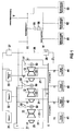
- FIG. 1 shows two steam pressure rails for different steam pressures and two voltage pressure rails for different voltages.
- Such systems with different steam pressure rails on the one hand and voltage rails on the other hand can often be found in systems in which consumers demand different steam pressures and electrical power supplies differently.
- FIG. 1 shows a first pressure system with steam consumers 41 and 42 into which steam turbines 11 and 12 emit steam.
- a second pressure system with steam consumers 43 and 44 is identified by 2 and is partly fed by the steam turbine 12 and entirely by the steam turbine 13.
- the capacity of the individual steam turbines 11 to 13 is different both electrically and on the steam side.
- gas-fired boilers 31 and 32 for example, supply the steam turbines 11 to 13 with steam via a busbar I.
- steam generated with process waste heat is added from the boiler 33 to the steam turbine 13.
- the steam turbines 11 to 13 each feed the pressure system 1 with higher pressure via their taps 21, while the pressure system 2 is supplied with lower pressure via the taps 22.
- the steam turbines 11 to 13 are each followed by the same generators 50, the current generated in the generator 50 being fed via block transformers 51 into a first voltage rail III.
- An external network is coupled to the rail III via a voltage rail 5, from which the required electrical energy is obtained, but to which electrical energy can also be delivered.
- the voltage rail III is connected via a transformer 55 with a rectifier 56 connected to a second voltage rail IV for direct current, from which consumers 61 to 62 are fed with a lower direct voltage.
- Such consumers are in an aluminum smelter e.g. the furnace furnaces required for the electrolysis. A higher AC voltage is available to the consumer 63.
- FIG. 2 shows a first steam circuit A for a steam pressure of, for example, 9 bar and a second steam circuit B for a second steam pressure of, for example, 13 bar.
- a steam pressure of, for example, 9 bar is particularly the case when boilers are retrofitted and converted, for example.
- Valves are installed in the individual pressure lines numbered in FIG. 2, some of which are controllable, which is not dealt with in detail here.
- individual condensate separators 103, 104, pressure relief devices 113, 114 for releasing steam that is not required, and display units 105, 115, 125 are each assigned to a predetermined number of boilers.
- three steam boilers 116, 127 and 124 are assigned to the first pressure system A in FIG. 2, which have different outputs, for example the boiler 116 specifically 4 t / h, the boiler 117 specifically 25 t / h and the boiler 124 likewise specifically 25 t /H.
- the printing system B with the higher one A total of six boilers 118 to 123 are assigned to steam pressure, the output of which ranges, for example, between 3 t / h and 20 t / h. Overall, the amount of steam required for different paper machines is covered.
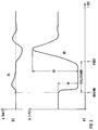
- the abscissa denotes time t.
- the steam consumption Q as mass flow is on the ordinate in sub-figure 3a and the vapor pressure p is plotted in sub-figure 3b, arbitrary units being selected.
- the relevant graphs are designated by 30 and 35 and thus represent, by way of example, the time course of the steam consumption or the associated steam pressure in a paper machine.
- the pressure curve in FIG. 3b shows corresponding deviations from the normal state, but which have the opposite tendency.
- the steam pressure p With reduced steam consumption Q, the steam pressure p naturally increases and only approaches the dashed setpoint after a maximum has been exceeded.
- the steam pressure p initially drops below the setpoint, and then, after oscillating around the setpoint, approaches the latter asymptotically.
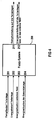
- FIG. 4 shows a fuzzy controller 200 with inputs 201 to 204 and outputs 211 and 212.
- the input 201 contains the steam consumption of all subsystems, the input 202 the electrical energy requirement of the subsystems, the input 203 the energy situation of the entire industrial system and the input 204 the energy situation of the external network.
- the fuzzification takes place according to predefined rules.
- the output 211 indicates the steam distribution and the input 212 the energy distribution to the subsystems. If necessary, energy feedback can be provided in the external network.
- the inputs 201 to 204 of the fuzzy controller 200 can include the steam consumption from the existing paper machines on the one hand and production interruptions on the other hand of individual paper machines.
- Such a loss of production takes into account in particular the so-called tear in the paper web or its duration, with the steam consumption being reduced immediately.
- fuzzy controller 200 it is possible to carry out the load distribution of all paper machines in such a way that the amount of steam currently required and the amount of steam required when restarting are distributed equally to the existing boilers 106 to 114 or individual boilers 106 to 114 are switched on and off .
- FIG. 5a shows an example of an action characteristic 51 of an individual boiler.
- the efficiency is plotted as a percentage over the boiler load of the boiler, whereby with 100% boiler load there is naturally a maximum in the performance curve.
- the associated points 1 to 4 were determined from a gas-operated boiler. In principle, corresponding characteristic curves result when other fossil fuels are used, whereby the starting point 1 is shifted, i.e. for example for lignite does not start at 20%, but at 50% efficiency.
- FIGS. 6a and 6b for a turbine: the efficiency of a turbine is usually between 80 and 95%, with an efficiency of 85% already being at 10% turbine output and an efficiency of over 90% at 50% turbine output and the maximum in turn is 100%.
- FIG. 6a corresponds to the efficiency of a turbine.
- fuzzy rules can be formulated. Rules from plant experience are usually used once; however, they can also be learned from process data. It is advantageous to start from an initial structure of the fuzzy rules and to expand these rules while the plant is in operation. The membership functions can be adjusted accordingly.
Landscapes
- Engineering & Computer Science (AREA)
- Artificial Intelligence (AREA)
- Software Systems (AREA)
- Physics & Mathematics (AREA)
- General Physics & Mathematics (AREA)
- Combustion & Propulsion (AREA)
- Health & Medical Sciences (AREA)
- Computer Vision & Pattern Recognition (AREA)
- Evolutionary Computation (AREA)
- Medical Informatics (AREA)
- Fuzzy Systems (AREA)
- Automation & Control Theory (AREA)
- Chemical & Material Sciences (AREA)
- Mathematical Physics (AREA)
- Mechanical Engineering (AREA)
- General Engineering & Computer Science (AREA)
- Control Of Steam Boilers And Waste-Gas Boilers (AREA)
- Treatment Of Sludge (AREA)
- Physical Or Chemical Processes And Apparatus (AREA)
- Feedback Control In General (AREA)
- Control Of Eletrric Generators (AREA)
Applications Claiming Priority (2)
| Application Number | Priority Date | Filing Date | Title |
|---|---|---|---|
| DE4435044A DE4435044A1 (de) | 1994-09-30 | 1994-09-30 | Verfahren zur Last- und Energieverteilung einer Industrieanlage sowie zugehörige Anordnung |
| DE4435044 | 1994-09-30 |
Publications (2)
| Publication Number | Publication Date |
|---|---|
| EP0704777A1 true EP0704777A1 (fr) | 1996-04-03 |
| EP0704777B1 EP0704777B1 (fr) | 1999-03-03 |
Family
ID=6529660
Family Applications (1)
| Application Number | Title | Priority Date | Filing Date |
|---|---|---|---|
| EP95115331A Expired - Lifetime EP0704777B1 (fr) | 1994-09-30 | 1995-09-28 | Procédé pour la répartition de charge et d'énergie dans une installation industrielle et dispositif pour sa mise en oeuvre |
Country Status (3)
| Country | Link |
|---|---|
| EP (1) | EP0704777B1 (fr) |
| AT (1) | ATE177216T1 (fr) |
| DE (2) | DE4435044A1 (fr) |
Cited By (2)
| Publication number | Priority date | Publication date | Assignee | Title |
|---|---|---|---|---|
| WO2000060227A1 (fr) * | 1999-03-31 | 2000-10-12 | Siemens Aktiengesellschaft | Procede de regulation d'une turbine a vapeur a soutirage de vapeur, dispositif de regulation y relatif et turbine a vapeur a soutirage de vapeur |
| EP1081338A3 (fr) * | 1999-09-03 | 2003-04-23 | Siemens Aktiengesellschaft | Procédé pour le fonctionnement d'une centrale avec au moins un générateur de vapeur et au moins un générateur électrique |
Citations (2)
| Publication number | Priority date | Publication date | Assignee | Title |
|---|---|---|---|---|
| US4628462A (en) * | 1984-09-11 | 1986-12-09 | Westinghouse Electric Corp. | Multiplane optimization method and apparatus for cogeneration of steam and power |
| JPH05308727A (ja) * | 1992-04-28 | 1993-11-19 | Daioo Eng Kk | 自家発電電力の制御方法 |
Family Cites Families (1)
| Publication number | Priority date | Publication date | Assignee | Title |
|---|---|---|---|---|
| JPH06236202A (ja) * | 1993-02-10 | 1994-08-23 | Hitachi Ltd | プラントの運転方法及び装置 |
-
1994
- 1994-09-30 DE DE4435044A patent/DE4435044A1/de not_active Withdrawn
-
1995
- 1995-09-28 DE DE59505182T patent/DE59505182D1/de not_active Expired - Fee Related
- 1995-09-28 EP EP95115331A patent/EP0704777B1/fr not_active Expired - Lifetime
- 1995-09-28 AT AT95115331T patent/ATE177216T1/de not_active IP Right Cessation
Patent Citations (2)
| Publication number | Priority date | Publication date | Assignee | Title |
|---|---|---|---|---|
| US4628462A (en) * | 1984-09-11 | 1986-12-09 | Westinghouse Electric Corp. | Multiplane optimization method and apparatus for cogeneration of steam and power |
| JPH05308727A (ja) * | 1992-04-28 | 1993-11-19 | Daioo Eng Kk | 自家発電電力の制御方法 |
Non-Patent Citations (4)
| Title |
|---|
| BORK P ET AL: "FUZZY CONTROL ZUR OPTIMIERUNG DER KUEHLWASSERAUFBEREITUNG AN EINER CHEMIE-REAKTORANLAGE FUZZY CONTROL OPTIMIZATION OF THE COOLING WATER PREPARATION FOR A CHEMICAL REACTOR PLANT", AUTOMATISIERUNGSTECHNISCHE PRAXIS - ATP, vol. 35, no. 5, 1 May 1993 (1993-05-01), pages 306 - 309, XP000369648 * |
| FUIERER P ET AL: "TAGESEINSATZOPTIMIERUNG FUR KRAFTWERKS-SYSTEME MIT KRAFT-WARME-KOPPLUNG", BWK BRENNSTOFF WARME KRAFT, vol. 41, no. 6, pages 273 - 277, XP000027996 * |
| JARMO FRANSSILA ET AL: "FUZZY CONTROL OF AN INDUSTRIAL ROBOT IN TRANSPUTER ENVIRONMENT", ROBOTICS, CIM AND AUTOMATION, EMERGING TECHNOLOGIES, SAN DIEGO, NOV. 9 - 13, 1992, vol. 2 OF 3, 9 November 1992 (1992-11-09), INSTITUTE OF ELECTRICAL AND ELECTRONICS ENGINEERS, pages 624 - 629, XP000356706 * |
| PATENT ABSTRACTS OF JAPAN vol. 18, no. 113 (E - 1514) 23 February 1994 (1994-02-23) * |
Cited By (4)
| Publication number | Priority date | Publication date | Assignee | Title |
|---|---|---|---|---|
| WO2000060227A1 (fr) * | 1999-03-31 | 2000-10-12 | Siemens Aktiengesellschaft | Procede de regulation d'une turbine a vapeur a soutirage de vapeur, dispositif de regulation y relatif et turbine a vapeur a soutirage de vapeur |
| US6497099B2 (en) | 1999-03-31 | 2002-12-24 | Siemens Aktiengesellschaft | Method and device for controlling a steam turbine with a steam bleed |
| KR100724813B1 (ko) * | 1999-03-31 | 2007-06-04 | 지멘스 악티엔게젤샤프트 | 증기 태핑부를 포함하는 증기터빈을 조절하기 위한 방법 및 장치 |
| EP1081338A3 (fr) * | 1999-09-03 | 2003-04-23 | Siemens Aktiengesellschaft | Procédé pour le fonctionnement d'une centrale avec au moins un générateur de vapeur et au moins un générateur électrique |
Also Published As
| Publication number | Publication date |
|---|---|
| DE59505182D1 (de) | 1999-04-08 |
| DE4435044A1 (de) | 1996-04-04 |
| ATE177216T1 (de) | 1999-03-15 |
| EP0704777B1 (fr) | 1999-03-03 |
Similar Documents
| Publication | Publication Date | Title |
|---|---|---|
| EP1371129B1 (fr) | Procede servant a regler un systeme d'inverseur | |
| DE68922266T2 (de) | Abwärmekessel und Verfahren zu dessen Verwendung. | |
| EP3048687B1 (fr) | Procede de commande d'un reseau de distribution d'energie electrique | |
| EP0697120B1 (fr) | Appareil de gestion pour generateurs d'energie electrique | |
| DE102021125875B4 (de) | Verfahren zum Betrieb eines Elektrolyseurs und einer Brennstoffzelle über einen gemeinsamen Wandler, Vorrichtung und Elektrolyseanlage | |
| EP1489300A1 (fr) | Procédé de commande d'une éolienne | |
| DE102008040272B4 (de) | Steuereinrichtung und Verfahren zum Steuern eines an eine Energieversorgung angeschlossenen Geräts | |
| DE10119624A1 (de) | Verfahren zum Betreiben einer Windenergieanlage | |
| DE102011106114A1 (de) | Verfahren zur Verteilung von elektrischer Energie in einem Stromnetzwerk mit einer Vielzahl von Verteilungszellen | |
| DE4302900A1 (en) | Power-heat coupling system e.g. for waste heat of fuel cell - has control equipment controlling heat generating equipment dependent on value of external electrical load detected by detecting apparatus | |
| DE102018129810A1 (de) | Verfahren und Vorrichtung zur Steuerung einer Anzahl von energieeinspeisenden und/oder energieverbrauchender Einheiten | |
| DE102014014091B4 (de) | Verfahren und Anordnung zum Betreiben eines Elektrolyseurs, Elektrolyseanlage und Methanisierungsanlage | |
| EP3297115B1 (fr) | Système comprenant un dispositif d'accumulation d'énergie et un convertisseur d'énergie destiné à recevoir de l'énergie électrique provenant d'un réseau électrique et fournir l'énergie électrique au réseau électrique | |
| EP1426564A1 (fr) | Procédé et dispositif pour la régulation de la puissance d' une centrale thermique à cycle combiné | |
| EP0704777B1 (fr) | Procédé pour la répartition de charge et d'énergie dans une installation industrielle et dispositif pour sa mise en oeuvre | |
| EP0861366B1 (fr) | Procede et dispositif pour la regulation rapide de la production d'une centrale electrique | |
| DE102018200017A1 (de) | Verfahren und vorrichtung zur energieversorgung eines antriebssystems mit zwischenkreis | |
| EP1309063B1 (fr) | Système pour injecter du courant de générateur de courant continu dans le réseau de courant alternatif | |
| WO2021037673A1 (fr) | Procédé destiné à commander des flux de puissance électrique | |
| EP0030321B1 (fr) | Procédé et dispositif pour optimaliser une installation pour électro-filtre | |
| EP3506028A1 (fr) | Système et procédé de la fourniture d'énergie à un consommateur | |
| DE19654620A1 (de) | Verfahren und Einrichtung zur gleichmäßigen Lastverteilung in Unterverteilungen von öffentlichen oder privaten Verteilungsnetzen | |
| DE10138399A1 (de) | Verfahren zum Betreiben einer Windenergieanlage | |
| EP0704778B1 (fr) | Procédé de distribution d'énergie dans des installations et dispositif pour sa mise en oeuvre | |
| EP2400360A1 (fr) | Appareil d'automatisation et procédé d'optimisation d'énergie |
Legal Events
| Date | Code | Title | Description |
|---|---|---|---|
| PUAI | Public reference made under article 153(3) epc to a published international application that has entered the european phase |
Free format text: ORIGINAL CODE: 0009012 |
|
| AK | Designated contracting states |
Kind code of ref document: A1 Designated state(s): AT BE CH DE DK ES FR GB GR IE IT LI NL PT SE |
|
| K1C1 | Correction of patent application (title page) published |
Effective date: 19960403 |
|
| 17P | Request for examination filed |
Effective date: 19961004 |
|
| 17Q | First examination report despatched |
Effective date: 19961128 |
|
| GRAG | Despatch of communication of intention to grant |
Free format text: ORIGINAL CODE: EPIDOS AGRA |
|
| GRAG | Despatch of communication of intention to grant |
Free format text: ORIGINAL CODE: EPIDOS AGRA |
|
| GRAH | Despatch of communication of intention to grant a patent |
Free format text: ORIGINAL CODE: EPIDOS IGRA |
|
| GRAH | Despatch of communication of intention to grant a patent |
Free format text: ORIGINAL CODE: EPIDOS IGRA |
|
| GRAA | (expected) grant |
Free format text: ORIGINAL CODE: 0009210 |
|
| AK | Designated contracting states |
Kind code of ref document: B1 Designated state(s): AT BE CH DE DK ES FR GB GR IE IT LI NL PT SE |
|
| PG25 | Lapsed in a contracting state [announced via postgrant information from national office to epo] |
Ref country code: SE Free format text: THE PATENT HAS BEEN ANNULLED BY A DECISION OF A NATIONAL AUTHORITY Effective date: 19990303 Ref country code: NL Free format text: LAPSE BECAUSE OF FAILURE TO SUBMIT A TRANSLATION OF THE DESCRIPTION OR TO PAY THE FEE WITHIN THE PRESCRIBED TIME-LIMIT Effective date: 19990303 Ref country code: IT Free format text: LAPSE BECAUSE OF FAILURE TO SUBMIT A TRANSLATION OF THE DESCRIPTION OR TO PAY THE FEE WITHIN THE PRE;WARNING: LAPSES OF ITALIAN PATENTS WITH EFFECTIVE DATE BEFORE 2007 MAY HAVE OCCURRED AT ANY TIME BEFORE 2007. THE CORRECT EFFECTIVE DATE MAY BE DIFFERENT FROM THE ONE RECORDED.SCRIBED TIME-LIMIT Effective date: 19990303 Ref country code: GR Free format text: LAPSE BECAUSE OF NON-PAYMENT OF DUE FEES Effective date: 19990303 Ref country code: GB Free format text: LAPSE BECAUSE OF NON-PAYMENT OF DUE FEES Effective date: 19990303 Ref country code: FR Free format text: LAPSE BECAUSE OF FAILURE TO SUBMIT A TRANSLATION OF THE DESCRIPTION OR TO PAY THE FEE WITHIN THE PRESCRIBED TIME-LIMIT Effective date: 19990303 Ref country code: ES Free format text: THE PATENT HAS BEEN ANNULLED BY A DECISION OF A NATIONAL AUTHORITY Effective date: 19990303 |
|
| REF | Corresponds to: |
Ref document number: 177216 Country of ref document: AT Date of ref document: 19990315 Kind code of ref document: T |
|
| REG | Reference to a national code |
Ref country code: CH Ref legal event code: EP |
|
| REG | Reference to a national code |
Ref country code: IE Ref legal event code: FG4D Free format text: GERMAN |
|
| REF | Corresponds to: |
Ref document number: 59505182 Country of ref document: DE Date of ref document: 19990408 |
|
| PG25 | Lapsed in a contracting state [announced via postgrant information from national office to epo] |
Ref country code: DK Free format text: LAPSE BECAUSE OF FAILURE TO SUBMIT A TRANSLATION OF THE DESCRIPTION OR TO PAY THE FEE WITHIN THE PRESCRIBED TIME-LIMIT Effective date: 19990603 |
|
| PG25 | Lapsed in a contracting state [announced via postgrant information from national office to epo] |
Ref country code: PT Free format text: LAPSE BECAUSE OF FAILURE TO SUBMIT A TRANSLATION OF THE DESCRIPTION OR TO PAY THE FEE WITHIN THE PRESCRIBED TIME-LIMIT Effective date: 19990604 |
|
| EN | Fr: translation not filed | ||
| NLV1 | Nl: lapsed or annulled due to failure to fulfill the requirements of art. 29p and 29m of the patents act | ||
| GBV | Gb: ep patent (uk) treated as always having been void in accordance with gb section 77(7)/1977 [no translation filed] |
Effective date: 19990303 |
|
| PG25 | Lapsed in a contracting state [announced via postgrant information from national office to epo] |
Ref country code: AT Free format text: LAPSE BECAUSE OF NON-PAYMENT OF DUE FEES Effective date: 19990928 |
|
| PG25 | Lapsed in a contracting state [announced via postgrant information from national office to epo] |
Ref country code: LI Free format text: LAPSE BECAUSE OF NON-PAYMENT OF DUE FEES Effective date: 19990930 Ref country code: CH Free format text: LAPSE BECAUSE OF NON-PAYMENT OF DUE FEES Effective date: 19990930 Ref country code: BE Free format text: LAPSE BECAUSE OF NON-PAYMENT OF DUE FEES Effective date: 19990930 |
|
| PG25 | Lapsed in a contracting state [announced via postgrant information from national office to epo] |
Ref country code: IE Free format text: LAPSE BECAUSE OF NON-PAYMENT OF DUE FEES Effective date: 19991019 |
|
| REG | Reference to a national code |
Ref country code: IE Ref legal event code: FD4D |
|
| PLBE | No opposition filed within time limit |
Free format text: ORIGINAL CODE: 0009261 |
|
| STAA | Information on the status of an ep patent application or granted ep patent |
Free format text: STATUS: NO OPPOSITION FILED WITHIN TIME LIMIT |
|
| 26N | No opposition filed | ||
| BERE | Be: lapsed |
Owner name: SIEMENS A.G. Effective date: 19990930 |
|
| REG | Reference to a national code |
Ref country code: CH Ref legal event code: PL |
|
| PG25 | Lapsed in a contracting state [announced via postgrant information from national office to epo] |
Ref country code: DE Free format text: LAPSE BECAUSE OF NON-PAYMENT OF DUE FEES Effective date: 20000701 |