EP0704778B1 - Procédé de distribution d'énergie dans des installations et dispositif pour sa mise en oeuvre - Google Patents
Procédé de distribution d'énergie dans des installations et dispositif pour sa mise en oeuvre Download PDFInfo
- Publication number
- EP0704778B1 EP0704778B1 EP95115355A EP95115355A EP0704778B1 EP 0704778 B1 EP0704778 B1 EP 0704778B1 EP 95115355 A EP95115355 A EP 95115355A EP 95115355 A EP95115355 A EP 95115355A EP 0704778 B1 EP0704778 B1 EP 0704778B1
- Authority
- EP
- European Patent Office
- Prior art keywords
- energy
- fuzzy
- consumers
- steam
- individual
- Prior art date
- Legal status (The legal status is an assumption and is not a legal conclusion. Google has not performed a legal analysis and makes no representation as to the accuracy of the status listed.)
- Expired - Lifetime
Links
Images



Classifications
-
- F—MECHANICAL ENGINEERING; LIGHTING; HEATING; WEAPONS; BLASTING
- F01—MACHINES OR ENGINES IN GENERAL; ENGINE PLANTS IN GENERAL; STEAM ENGINES
- F01K—STEAM ENGINE PLANTS; STEAM ACCUMULATORS; ENGINE PLANTS NOT OTHERWISE PROVIDED FOR; ENGINES USING SPECIAL WORKING FLUIDS OR CYCLES
- F01K17/00—Using steam or condensate extracted or exhausted from steam engine plant
- F01K17/02—Using steam or condensate extracted or exhausted from steam engine plant for heating purposes, e.g. industrial, domestic
-
- G—PHYSICS
- G05—CONTROLLING; REGULATING
- G05B—CONTROL OR REGULATING SYSTEMS IN GENERAL; FUNCTIONAL ELEMENTS OF SUCH SYSTEMS; MONITORING OR TESTING ARRANGEMENTS FOR SUCH SYSTEMS OR ELEMENTS
- G05B13/00—Adaptive control systems, i.e. systems automatically adjusting themselves to have a performance which is optimum according to some preassigned criterion
- G05B13/02—Adaptive control systems, i.e. systems automatically adjusting themselves to have a performance which is optimum according to some preassigned criterion electric
- G05B13/0265—Adaptive control systems, i.e. systems automatically adjusting themselves to have a performance which is optimum according to some preassigned criterion electric the criterion being a learning criterion
- G05B13/0275—Adaptive control systems, i.e. systems automatically adjusting themselves to have a performance which is optimum according to some preassigned criterion electric the criterion being a learning criterion using fuzzy logic only
-
- Y—GENERAL TAGGING OF NEW TECHNOLOGICAL DEVELOPMENTS; GENERAL TAGGING OF CROSS-SECTIONAL TECHNOLOGIES SPANNING OVER SEVERAL SECTIONS OF THE IPC; TECHNICAL SUBJECTS COVERED BY FORMER USPC CROSS-REFERENCE ART COLLECTIONS [XRACs] AND DIGESTS
- Y02—TECHNOLOGIES OR APPLICATIONS FOR MITIGATION OR ADAPTATION AGAINST CLIMATE CHANGE
- Y02E—REDUCTION OF GREENHOUSE GAS [GHG] EMISSIONS, RELATED TO ENERGY GENERATION, TRANSMISSION OR DISTRIBUTION
- Y02E20/00—Combustion technologies with mitigation potential
- Y02E20/14—Combined heat and power generation [CHP]
-
- Y—GENERAL TAGGING OF NEW TECHNOLOGICAL DEVELOPMENTS; GENERAL TAGGING OF CROSS-SECTIONAL TECHNOLOGIES SPANNING OVER SEVERAL SECTIONS OF THE IPC; TECHNICAL SUBJECTS COVERED BY FORMER USPC CROSS-REFERENCE ART COLLECTIONS [XRACs] AND DIGESTS
- Y02—TECHNOLOGIES OR APPLICATIONS FOR MITIGATION OR ADAPTATION AGAINST CLIMATE CHANGE
- Y02P—CLIMATE CHANGE MITIGATION TECHNOLOGIES IN THE PRODUCTION OR PROCESSING OF GOODS
- Y02P80/00—Climate change mitigation technologies for sector-wide applications
- Y02P80/10—Efficient use of energy, e.g. using compressed air or pressurized fluid as energy carrier
- Y02P80/15—On-site combined power, heat or cool generation or distribution, e.g. combined heat and power [CHP] supply
Definitions
- the invention relates to a method for energy distribution in systems, especially in complex technical ones Plants with a plurality of sub-plants, with means for Conversion of primary energy sources into electrical energy on the one hand and in process steam on the other hand and with several Energy consumers.
- the invention also relates on the associated arrangement for performing such Procedure. Any system in which Energy of different types in terms of time and quantity is generated and consumed variably.
- the object of the invention is the energy distribution in systems, especially in technical systems with a plurality of sub-systems to improve and an associated Specify order.
- fuzzy logic is used for optimal Power distribution in the system in which all subsystems are operated in their work area.
- the amount of energy is determined cyclically using the fuzzy rules and where the fuzzy rules are information of individual consumers about their current electrical energy and Steam purchase, their current and future energy status and the urgency of maintaining energy supply of production included.
- the fuzzy rules are information of individual consumers about their current electrical energy and Steam purchase, their current and future energy status and the urgency of maintaining energy supply of production included.
- the fuzzy system is arranged, the fuzzy system consisting of one first block to assess the whole situation, one second block to evaluate consumers and a third Block for specifying the individual references to energy exists.
- fuzzy logic can be combined with Petri nets. So that the Energy distribution especially in the case of a pulp and / or Paper mill as a production plant, which is essentially through characterized a variable steam consumption of the subsystems is, both in terms of steam generation and that optimize consumption in this regard.
- Fuzzy logic and / or Petri networks are state of the art already known, for example "Automation technology Kir”, Vol. 35, No. 5 (May 1993), pages 306 to 309, and "Technische Rundschau", Vol. 85, No. 24 (June 18, 1993), Pages 28 to 33. With such systems, however only simple automation tasks, especially for regulation of material flows, are processed.
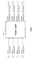
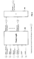
- a fuzzy system is identified by 100 in FIG.
- the data from energy producers such as individual boilers 51 and 52, which for Steam generation, and for example a turbine 50, which is used to generate electrical energy.
- energy producers such as individual boilers 51 and 52, which for Steam generation, and for example a turbine 50, which is used to generate electrical energy.
- other parameters can be entered, to the following is still assumed in detail.
- the fuzzy system 100 consumers 121, 122 etc. are connected downstream.
- average curves for electrical energy consumption e.g.
- Block I provides the evaluation of the Overall situation of energy consumption
- block II the assessment of individual consumers
- block III the determination of the individual references.
- the marked ones are in detail
- the signal flow are the Numbered signal quantities.
- Block I is essential in the representation according to FIG. 2, the changing to assess the overall situation Boundary conditions can take into account.
- Fuzzification the maximum and minimum values of the consumers Units 130, 140 given that allow, within the scope of Fuzzification of the input variables the respective membership functions to compress or stretch. The latter will for the general case in the older German patent application P 44 25 674.4 proposed and explained in detail. This can be done online, making the changing Boundary conditions should be taken into account.
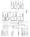
- a fuzzy system 107 is present in FIG. 3, into which input signals are input the status and relationship of each consumer can be entered.
- the priority is as output signals the individual consumer for maximum benefit on the one hand and minimum benefit on the other hand spent.
- FIG. 4 shows a fuzzy system 108, in which, in addition to the signals according to FIG. 3, the time of day and the associated date are also fed in as further input variables.
- the starting sizes for the consumers 1 to n at time t + t o are applied to an adder 150, the result of which defines the required energy with respect to the lead-time.
- Fuzzy systems 109, 110 and 111 are present, which in particular the external procurement of energy from other energy supply companies (EVU) with the own generation of the existing turbines and the current consumption with reference to the lead time of individual consumers combined.
- EEU energy supply companies
- the values with the lead time t + t0 calculated, which results in a load distribution reserve.
- the rules for the purchase of electrical energy from external networks can as information according to FIG 5 on the Average daily curves of total energy consumption in access the relevant network.
- information used about the expected energy consumption are there time-cyclical consumption curves for consumers, these are used for rules that serve energy planning utilized. For example, certain energy consumption is in Expect time intervals, with the relevant scanning times depend on the start-up time of the energy producers and the necessary parking and coordination times for the other consumers.
- the fuzzy methods described can be used with conventional Procedure for determining the input variables in the fuzzy systems, such as. Procedure for determining the average curves for electrical energy, i.e. the daily curve, work together.
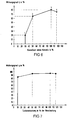
- FIG. 6 shows an action characteristic of an individual boiler shown as an example.
- the efficiency is plotted over the boiler load of the boiler in percent, whereby at 100% boiler load naturally a maximum in the performance curve results.
- the corresponding points 1 to 4 were in a gas-fired boiler. In principle arise corresponding when using other fossil fuels Characteristic curves, whereby the point of use 1 is shifted. For example, not for lignite at 20%, but at 50% efficiency begins.
- the efficiency of a turbine is usually between 80 and 95%, whereby already 10% turbine performance an efficiency of 85% is present at 50% turbine performance an efficiency of over 90% is reached and the maximum is again 100%.
- the graphs 81 and 91 represent membership functions ⁇ (x) represents the truthfulness of the blurred Expresses crowd.
- the function ⁇ (x) evaluates each element of the Quantity with a real number between 0 and 1.
- the membership functions ⁇ (x) according to FIG 8 and 9 each express a possibility assessment in terms of content. They differ significantly from the probability assessment in statistics. With a so defined Affiliation ⁇ (x), the blur can be displayed on a computer and predictable. Especially for energy management According to one of FIGS. 1 to 5, advantageous applications can be made derive.
- the Fuzzy-Petri network is a model concept for operational decision-making processes in complex production systems by the knowledge of system structure together with technological Experiences of the investment experts for the selection of operational tax activities. Let it go between the process and fuzzy petri networks in a known manner Define assignments, in particular the components of the Petri network is linked to the energy distribution system. For example, the transitions correspond to the Petri network certain tax operations, the places of the Petri network certain work progress regulations, the brand stream of the Petri network the object or material flow and the flow reaction of the Petri network the system structure of any Production facility.
- Petri networks are for description the control operations to be carried out one after the other and in parallel particularly suitable.
- the fuzzy petri network concept connects this using the blur of fuzzy technology the description concept of parallel processes Petri nets.
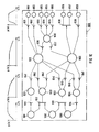
- FIG 10 For use in an energy distribution system modeling with a fuzzy Petri network is advantageous. This is shown in FIG 10 specifically for Modeling the steam network of an integrated pulp and Paper mill shown: Here are the process conditions by places, i.e. Circles in the model, made clear. Of the Entry of electrical energy is controlled by the load regulator regulated individual consumers. These are the energy system control elements and are represented in the Petri net as transitions, which is the energy from one producer to a consumer transmits. The latter consumption is kept flexible through the controller setting and is therefore known as Fuzzy switching point of the transitions specified.
- FIG 10 shown fuzzy Petri network as a model concept for the Steam distribution used.
- the control actions or control element settings are determined with their conditions of use blurred by transitions (vertical lines) and Places (circles) expressed in the Petri net.
- the availability of energy producers and consumer requirements describe the process conditions for the adjustment the steam flows and are identified by places in the model, which correspond to consumers with brands are filled. To change the generation or consumption do not serve in detail illustrated actuators. she press the control options in the energy distribution out.
- the latter are caused by transitions described, which the steam from the upstream system in a predefined ratio to the downstream system transfer. Since the transfer process is flexible, it will also referred to as unsharp behavior of the transitions. Of the Brand content of the places thus determines the time for Changes in the adjacent transitions. By the Switching of the transitions occurs sometime between the places a brand stream that, like the steam stream between producers, Distributors and consumers from the entry points Starting places is transformed.
- FIG. 10 shows 1000 in the fuzzy petri network shown three boilers 1001, 1002 and 1003 and four turbines 1021 to 1024 optionally a low pressure (LP) steam rail 1010 and assigned to a high pressure (HD) steam rail 1020.
- the latter is a steam storage 1030 downstream and there are Range of consumers 1051 to 1058 available.
- Farther are in the columns of the places shown in FIG 10 in the The first line shows examples of individual membership functions ⁇ (x) indicated.
- the fuzzy petri network enables those already defined System connections and relationships are made more flexible. Such models can be used with great efficiency in the 1 to 5 described power distribution systems be used.
- An inference machine is assigned to the fuzzy petri network model. Together with this inference machine, it imagines knowledge-based system. The inference machine is there specially developed for the fuzzy petri network. The Fuzzy-Petri network itself forms the knowledge base.
- the inference is as follows: Starting from the on The adjacent transitions will be the worst rated place (Settings) changed until the place is no longer the worst. It will be iterative for so long repeated for all places until the target rating of the network is an optimum. The settings of the transitions are connected to the process and then transfer the online Network in the next state. Starts in this new state the inference cycle again. By changing the membership functions the decision-making behavior becomes in places and transitions programmed by the inference machine, e.g. by having a place a closer membership function and thereby receives a higher sensitivity, so that the Inference other transition settings are triggered.
Landscapes
- Engineering & Computer Science (AREA)
- Artificial Intelligence (AREA)
- Physics & Mathematics (AREA)
- Software Systems (AREA)
- Health & Medical Sciences (AREA)
- Medical Informatics (AREA)
- Mechanical Engineering (AREA)
- Fuzzy Systems (AREA)
- Mathematical Physics (AREA)
- Combustion & Propulsion (AREA)
- Chemical & Material Sciences (AREA)
- Computer Vision & Pattern Recognition (AREA)
- Evolutionary Computation (AREA)
- General Engineering & Computer Science (AREA)
- General Physics & Mathematics (AREA)
- Automation & Control Theory (AREA)
- Management, Administration, Business Operations System, And Electronic Commerce (AREA)
- Engine Equipment That Uses Special Cycles (AREA)
- Feedback Control In General (AREA)
- Radiation-Therapy Devices (AREA)
- Variable-Direction Aerials And Aerial Arrays (AREA)
Claims (15)
- Procédé pour répartir de l'énergie dans des systèmes, notamment dans des installations techniques complexes comportant une pluralité d'installations partielles, comportant des moyens pour transformer des sources d'énergie primaires en énergie électrique d'une part et en vapeur de processus d'autre part et comportant plusieurs dispositifs consommateurs d'énergie, caractérisé en ce que pour une répartition d'énergie optimale dans le système, selon laquelle toutes les installations partielles ou dispositifs consommateurs fonctionnent dans leur zone de fonctionnement, on fait appel à une logique floue, pour laquelle on utilise pour coordonner la répartition d'énergie et la production d'énergie les connaissances dues à l'expérience de l'utilisateur dans des règles de logique floue, les règles de logique floue contenant des informations des dispositifs consommateurs individuels en ce qui concerne leur vapeur et énergie électrique actuelle, leur état d'énergie présent et futur et l'urgence de fourniture d'énergie pour le maintien de la production.
- Procédé suivant la revendication 1, caractérisé en ce que les quantités d'énergie prélevées par les dispositifs consommateurs individuels sont déterminées de manière cyclique à l'aide des règles de logique floue.
- Procédé suivant la revendication 1, caractérisé en ce que les règles de logique floue sont utilisées pour faire fonctionner le système d'automatisation. qui coordonne la répartition d'énergie et la production d'énergie
- Procédé suivant la revendication 3, caractérisé en ce que la logique floue est utilisée en combinaison avec des modèles mathématiques et des procédés de formation de bilan pour la répartition d'énergie.
- Procédé suivant la revendication 2, caractérisé en ce que des règles de logique floue contiennent la mise en circuit d'une part des producteurs de vapeur et des turbines et d'autre part l'acquisition d'énergie électrique provenant du réseau.
- Procédé suivant la revendication 5, caractérisé en ce que pour l'acquisition d'énergie électrique provenant de réseaux étrangers, on utilise, des informations supplémentaires provenant des courbes quotidiennes moyennes de la consommation totale d'énergie .
- Procédé suivant la revendication 6, caractérisé en ce que on utilise des courbes de consommation cycliques dans le temps pour établir des règles de logique floue pour la planification de l'énergie.
- Procédé suivant l'une des revendications précédentes, caractérisé en ce que dans le système, des pondérations spécifiques sont associées aux dispositifs consommateurs individuels.
- Procédé suivant l'une des revendications précédentes, caractérisé en ce que les règles de logique floue sont intégrées par des réseaux de Pétri dans un réseau de Pétri de logique floue.
- Procédé suivant la revendication 1 et la revendication 9, caractérisé par une utilisation dans une papeterie ou une installation de fabrication de pâte chimique, notamment pour commander le régime de vapeur de différents dispositifs consommateurs dans la papeterie et/ou l'installation de fabrication de pâte chimique.
- Procédé suivant la revendication 10, caractérisé en ce que pour l'utilisation dans une papeterie et/ou installation de fabrication de pâte chimique, on utilise, pour l'établissement des règles de logique floueles règles d'action de l'utilisateur de l'installation,les connaissances concernant la production par analyse de processus et,les connaissances que l'on obtient par formation de bilan et modélisation des courants d'énergie et de vapeur.
- Dispositif pour la mise en oeuvre du procédé suivant la revendication 1 ou l'une des revendications 2 à 11, comportant des turbines et/ou des chaudières pour produire de l'énergie électrique d'une part et de la vapeur de processus d'autre part, et comportant plusieurs dispositifs consommateurs, caractérisé en ce que, entre les turbines (50) et/ou les chaudières (50, 51) et les dispositifs consommateurs (121, 122), il est inerposé au moins un système (100) à logique floue. qui est constitué d'un premier bloc (I) pour l'évaluation de la situation globale, d'un deuxième bloc (II) pour l'évaluation des dispositifs consommateurs et d'un troisième bloc (III) pour la détermination des acquisition individuelle d'énergie.
- Dispositif suivant la revendication 12, caractérisé en ce que le système (100) à logique floue comprend un certain nombre de régulateurs (101 à 111) à logique floue individuels.
- Dispositif suivant la revendication 12, caractérisé en ce que des régulateurs (103, 104) à logique floue individuels comportent des moyens (130, 140) destinés à une modification en ligne des fonctions d'appartenance lors de la fuzzification.
- Dispositif suivant la revendication 12, caractérisé en ce qu'il est associé au système à logique floue des réseaux de Pétri, qui forment ensemble un modèle (100) de réseau de Pétri à logique floue.
Applications Claiming Priority (2)
| Application Number | Priority Date | Filing Date | Title |
|---|---|---|---|
| DE4435038A DE4435038A1 (de) | 1994-09-30 | 1994-09-30 | Verfahren zur Energieverteilung in Systemen und zugehörige Anordnung |
| DE4435038 | 1994-09-30 |
Publications (2)
| Publication Number | Publication Date |
|---|---|
| EP0704778A1 EP0704778A1 (fr) | 1996-04-03 |
| EP0704778B1 true EP0704778B1 (fr) | 1999-03-03 |
Family
ID=6529655
Family Applications (1)
| Application Number | Title | Priority Date | Filing Date |
|---|---|---|---|
| EP95115355A Expired - Lifetime EP0704778B1 (fr) | 1994-09-30 | 1995-09-28 | Procédé de distribution d'énergie dans des installations et dispositif pour sa mise en oeuvre |
Country Status (3)
| Country | Link |
|---|---|
| EP (1) | EP0704778B1 (fr) |
| AT (1) | ATE177217T1 (fr) |
| DE (2) | DE4435038A1 (fr) |
Cited By (1)
| Publication number | Priority date | Publication date | Assignee | Title |
|---|---|---|---|---|
| DE10317183A1 (de) * | 2003-04-15 | 2004-11-11 | SWE Strom und Fernwärme GmbH | Temporäre Steigerung durch KWK erzeugter elektrischer Energie |
Families Citing this family (3)
| Publication number | Priority date | Publication date | Assignee | Title |
|---|---|---|---|---|
| DE19942114A1 (de) * | 1999-09-03 | 2001-03-15 | Siemens Ag | Verfahren zum Betrieb einer Anlage mit mindestens einem Dampferzeuger und mindestens einem Stromerzeuger |
| AT501847B1 (de) * | 2005-02-02 | 2007-04-15 | Innovative Elektrotechnische P | Verfahren zum erzeugen eines frühindikatorsignals |
| DE202005010265U1 (de) * | 2005-06-28 | 2006-06-29 | Reichelt, Maureen | BHKW-System auf Abfall/Biomassebasis mit Wärmekopplung unter Einbezug von Alt-Deponien |
Family Cites Families (1)
| Publication number | Priority date | Publication date | Assignee | Title |
|---|---|---|---|---|
| JPH05308727A (ja) * | 1992-04-28 | 1993-11-19 | Daioo Eng Kk | 自家発電電力の制御方法 |
-
1994
- 1994-09-30 DE DE4435038A patent/DE4435038A1/de not_active Withdrawn
-
1995
- 1995-09-28 AT AT95115355T patent/ATE177217T1/de not_active IP Right Cessation
- 1995-09-28 EP EP95115355A patent/EP0704778B1/fr not_active Expired - Lifetime
- 1995-09-28 DE DE59505183T patent/DE59505183D1/de not_active Expired - Fee Related
Cited By (2)
| Publication number | Priority date | Publication date | Assignee | Title |
|---|---|---|---|---|
| DE10317183A1 (de) * | 2003-04-15 | 2004-11-11 | SWE Strom und Fernwärme GmbH | Temporäre Steigerung durch KWK erzeugter elektrischer Energie |
| DE10317183B4 (de) * | 2003-04-15 | 2007-04-05 | SWE Strom und Fernwärme GmbH | Temporäre Steigerung durch KWK erzeugter elektrischer Energie |
Also Published As
| Publication number | Publication date |
|---|---|
| DE4435038A1 (de) | 1996-04-04 |
| EP0704778A1 (fr) | 1996-04-03 |
| DE59505183D1 (de) | 1999-04-08 |
| ATE177217T1 (de) | 1999-03-15 |
Similar Documents
| Publication | Publication Date | Title |
|---|---|---|
| DE69520934T2 (de) | Methode und system zur optimierung der nützlichkeit einer anlage | |
| DE10341764B4 (de) | Integrierte Modell-Vorhersagesteuerung und -Optimierung innerhalb eines Prozesssteuerungssystems | |
| DE69318889T2 (de) | Wirtschaftliche Echtzeitleistungszuordnung | |
| DE10341573A1 (de) | Integrierte modellbasierte prädikative Steuerung und Optimierung innerhalb eines Prozesssteuerungssystems | |
| DE102018003769A1 (de) | Vorrichtung für maschinelles Lernen, Servosteuersystem und Verfahren zum maschinellen Lernen | |
| WO2012076306A1 (fr) | Procédé de modélisation informatique d'un système technique | |
| WO2012048808A1 (fr) | Procédé et dispositif d'optimisation d'un processus de production | |
| DE102012216574A1 (de) | Verfahren zur rechnergestützten Steuerung und/oder Regelung eines technischen Systems | |
| DE102018129810A1 (de) | Verfahren und Vorrichtung zur Steuerung einer Anzahl von energieeinspeisenden und/oder energieverbrauchender Einheiten | |
| EP3075053B1 (fr) | Procédé de configuration assistée par ordinateur d'un réseau électrique | |
| DE19539479A1 (de) | Verfahren zum automatisierten Erstellen eines verfahrenstechnischen Schemas | |
| WO2023194492A1 (fr) | Procédé de surveillance d'un système électrochimique, et système électrochimique | |
| AT412678B (de) | Verfahren zur rechnergestützten erstellung von prognosen für operative systeme sowie system zur erstellung von prognosen für operative systeme | |
| DE602004012399T2 (de) | Vefahren zur Generierung von optimalen Steuerungsproblemen für industrielle Prozesse | |
| EP3985599B1 (fr) | Commande de réseaux énergétiques | |
| EP0704778A1 (fr) | Procédé de distribution d'énergie dans des installations et dispositif pour sa mise en oeuvre | |
| DE102011007434A1 (de) | Simulationsmodell für eine Windenergieanlage sowie Erstellung und Verwendung | |
| EP3376026B1 (fr) | Procédé de réglage de la puissance active d'un parc éolien et parc éolien correspondant | |
| EP3323183B1 (fr) | Procédé de commande, assistée par ordinateur, de la puissance dans un réseau de courant électrique | |
| DE3541148A1 (de) | Verfahren zur regelung einer dampfturbine | |
| DE10011607A1 (de) | Verfahren und Vorrichtung sowie Computerprogrammprodukt zum Betrieb einer technischen Anlage | |
| EP3432093A1 (fr) | Procédé de modélisation d'un système dynamique par apprentissage assisté par ordinateur de modèles commandés par données | |
| WO2023274666A1 (fr) | Procédé et unité de commande permettant de commander une grille thermique | |
| DE4235274C2 (de) | Verfahren zur Einrichtung und zum Betrieb eines Verbundes von elektrischen Geräten | |
| EP4080724A1 (fr) | Identification de la topologie des structures de compteur d'un système énergétique |
Legal Events
| Date | Code | Title | Description |
|---|---|---|---|
| PUAI | Public reference made under article 153(3) epc to a published international application that has entered the european phase |
Free format text: ORIGINAL CODE: 0009012 |
|
| AK | Designated contracting states |
Kind code of ref document: A1 Designated state(s): AT BE CH DE DK ES FR GB GR IE IT LI NL PT SE |
|
| 17P | Request for examination filed |
Effective date: 19960917 |
|
| 17Q | First examination report despatched |
Effective date: 19961128 |
|
| GRAG | Despatch of communication of intention to grant |
Free format text: ORIGINAL CODE: EPIDOS AGRA |
|
| GRAG | Despatch of communication of intention to grant |
Free format text: ORIGINAL CODE: EPIDOS AGRA |
|
| GRAH | Despatch of communication of intention to grant a patent |
Free format text: ORIGINAL CODE: EPIDOS IGRA |
|
| GRAH | Despatch of communication of intention to grant a patent |
Free format text: ORIGINAL CODE: EPIDOS IGRA |
|
| GRAA | (expected) grant |
Free format text: ORIGINAL CODE: 0009210 |
|
| AK | Designated contracting states |
Kind code of ref document: B1 Designated state(s): AT BE CH DE DK ES FR GB GR IE IT LI NL PT SE |
|
| PG25 | Lapsed in a contracting state [announced via postgrant information from national office to epo] |
Ref country code: SE Free format text: THE PATENT HAS BEEN ANNULLED BY A DECISION OF A NATIONAL AUTHORITY Effective date: 19990303 Ref country code: NL Free format text: LAPSE BECAUSE OF FAILURE TO SUBMIT A TRANSLATION OF THE DESCRIPTION OR TO PAY THE FEE WITHIN THE PRESCRIBED TIME-LIMIT Effective date: 19990303 Ref country code: IT Free format text: LAPSE BECAUSE OF FAILURE TO SUBMIT A TRANSLATION OF THE DESCRIPTION OR TO PAY THE FEE WITHIN THE PRE;WARNING: LAPSES OF ITALIAN PATENTS WITH EFFECTIVE DATE BEFORE 2007 MAY HAVE OCCURRED AT ANY TIME BEFORE 2007. THE CORRECT EFFECTIVE DATE MAY BE DIFFERENT FROM THE ONE RECORDED.SCRIBED TIME-LIMIT Effective date: 19990303 Ref country code: GR Free format text: LAPSE BECAUSE OF NON-PAYMENT OF DUE FEES Effective date: 19990303 Ref country code: GB Free format text: LAPSE BECAUSE OF NON-PAYMENT OF DUE FEES Effective date: 19990303 Ref country code: FR Free format text: LAPSE BECAUSE OF FAILURE TO SUBMIT A TRANSLATION OF THE DESCRIPTION OR TO PAY THE FEE WITHIN THE PRESCRIBED TIME-LIMIT Effective date: 19990303 Ref country code: ES Free format text: THE PATENT HAS BEEN ANNULLED BY A DECISION OF A NATIONAL AUTHORITY Effective date: 19990303 |
|
| REF | Corresponds to: |
Ref document number: 177217 Country of ref document: AT Date of ref document: 19990315 Kind code of ref document: T |
|
| REG | Reference to a national code |
Ref country code: CH Ref legal event code: EP |
|
| REG | Reference to a national code |
Ref country code: IE Ref legal event code: FG4D Free format text: GERMAN |
|
| REF | Corresponds to: |
Ref document number: 59505183 Country of ref document: DE Date of ref document: 19990408 |
|
| PG25 | Lapsed in a contracting state [announced via postgrant information from national office to epo] |
Ref country code: DK Free format text: LAPSE BECAUSE OF FAILURE TO SUBMIT A TRANSLATION OF THE DESCRIPTION OR TO PAY THE FEE WITHIN THE PRESCRIBED TIME-LIMIT Effective date: 19990603 |
|
| PG25 | Lapsed in a contracting state [announced via postgrant information from national office to epo] |
Ref country code: PT Free format text: LAPSE BECAUSE OF FAILURE TO SUBMIT A TRANSLATION OF THE DESCRIPTION OR TO PAY THE FEE WITHIN THE PRESCRIBED TIME-LIMIT Effective date: 19990604 |
|
| EN | Fr: translation not filed | ||
| NLV1 | Nl: lapsed or annulled due to failure to fulfill the requirements of art. 29p and 29m of the patents act | ||
| GBV | Gb: ep patent (uk) treated as always having been void in accordance with gb section 77(7)/1977 [no translation filed] |
Effective date: 19990303 |
|
| PG25 | Lapsed in a contracting state [announced via postgrant information from national office to epo] |
Ref country code: AT Free format text: LAPSE BECAUSE OF NON-PAYMENT OF DUE FEES Effective date: 19990928 |
|
| PG25 | Lapsed in a contracting state [announced via postgrant information from national office to epo] |
Ref country code: LI Free format text: LAPSE BECAUSE OF NON-PAYMENT OF DUE FEES Effective date: 19990930 Ref country code: CH Free format text: LAPSE BECAUSE OF NON-PAYMENT OF DUE FEES Effective date: 19990930 Ref country code: BE Free format text: LAPSE BECAUSE OF NON-PAYMENT OF DUE FEES Effective date: 19990930 |
|
| PG25 | Lapsed in a contracting state [announced via postgrant information from national office to epo] |
Ref country code: IE Free format text: LAPSE BECAUSE OF NON-PAYMENT OF DUE FEES Effective date: 19991019 |
|
| REG | Reference to a national code |
Ref country code: IE Ref legal event code: FD4D |
|
| PLBE | No opposition filed within time limit |
Free format text: ORIGINAL CODE: 0009261 |
|
| STAA | Information on the status of an ep patent application or granted ep patent |
Free format text: STATUS: NO OPPOSITION FILED WITHIN TIME LIMIT |
|
| 26N | No opposition filed | ||
| BERE | Be: lapsed |
Owner name: SIEMENS A.G. Effective date: 19990930 |
|
| REG | Reference to a national code |
Ref country code: CH Ref legal event code: PL |
|
| PG25 | Lapsed in a contracting state [announced via postgrant information from national office to epo] |
Ref country code: DE Free format text: LAPSE BECAUSE OF NON-PAYMENT OF DUE FEES Effective date: 20000701 |