EP0704778A1 - Procédé de distribution d'énergie dans des installations et dispositif pour sa mise en oeuvre - Google Patents
Procédé de distribution d'énergie dans des installations et dispositif pour sa mise en oeuvre Download PDFInfo
- Publication number
- EP0704778A1 EP0704778A1 EP95115355A EP95115355A EP0704778A1 EP 0704778 A1 EP0704778 A1 EP 0704778A1 EP 95115355 A EP95115355 A EP 95115355A EP 95115355 A EP95115355 A EP 95115355A EP 0704778 A1 EP0704778 A1 EP 0704778A1
- Authority
- EP
- European Patent Office
- Prior art keywords
- fuzzy
- energy
- consumers
- steam
- hand
- Prior art date
- Legal status (The legal status is an assumption and is not a legal conclusion. Google has not performed a legal analysis and makes no representation as to the accuracy of the status listed.)
- Granted
Links
- 238000000034 method Methods 0.000 title claims abstract description 40
- 238000009826 distribution Methods 0.000 claims abstract description 21
- 230000008569 process Effects 0.000 claims abstract description 17
- 238000005265 energy consumption Methods 0.000 claims description 11
- 238000004519 manufacturing process Methods 0.000 claims description 11
- 238000013178 mathematical model Methods 0.000 claims description 3
- 238000013439 planning Methods 0.000 claims description 2
- 230000005611 electricity Effects 0.000 claims 1
- 238000012423 maintenance Methods 0.000 claims 1
- 238000012549 training Methods 0.000 abstract description 2
- 230000007704 transition Effects 0.000 description 16
- 230000008859 change Effects 0.000 description 7
- 238000011156 evaluation Methods 0.000 description 4
- 238000000605 extraction Methods 0.000 description 3
- 238000012546 transfer Methods 0.000 description 3
- 238000006243 chemical reaction Methods 0.000 description 2
- 230000000694 effects Effects 0.000 description 2
- 238000007726 management method Methods 0.000 description 2
- 238000004061 bleaching Methods 0.000 description 1
- 238000004364 calculation method Methods 0.000 description 1
- 238000007796 conventional method Methods 0.000 description 1
- 238000010411 cooking Methods 0.000 description 1
- 230000003247 decreasing effect Effects 0.000 description 1
- 230000001419 dependent effect Effects 0.000 description 1
- 230000006866 deterioration Effects 0.000 description 1
- 238000010586 diagram Methods 0.000 description 1
- 238000005516 engineering process Methods 0.000 description 1
- 238000001704 evaporation Methods 0.000 description 1
- 230000008020 evaporation Effects 0.000 description 1
- 239000002803 fossil fuel Substances 0.000 description 1
- 238000010438 heat treatment Methods 0.000 description 1
- 238000009434 installation Methods 0.000 description 1
- 230000010354 integration Effects 0.000 description 1
- 230000003993 interaction Effects 0.000 description 1
- 239000003077 lignite Substances 0.000 description 1
- 239000000463 material Substances 0.000 description 1
- 238000005259 measurement Methods 0.000 description 1
- 238000005457 optimization Methods 0.000 description 1
- 230000001105 regulatory effect Effects 0.000 description 1
- 230000035945 sensitivity Effects 0.000 description 1
- 230000002123 temporal effect Effects 0.000 description 1
- 238000012384 transportation and delivery Methods 0.000 description 1
- 230000001960 triggered effect Effects 0.000 description 1
- 238000011144 upstream manufacturing Methods 0.000 description 1
Images




Classifications
-
- F—MECHANICAL ENGINEERING; LIGHTING; HEATING; WEAPONS; BLASTING
- F01—MACHINES OR ENGINES IN GENERAL; ENGINE PLANTS IN GENERAL; STEAM ENGINES
- F01K—STEAM ENGINE PLANTS; STEAM ACCUMULATORS; ENGINE PLANTS NOT OTHERWISE PROVIDED FOR; ENGINES USING SPECIAL WORKING FLUIDS OR CYCLES
- F01K17/00—Using steam or condensate extracted or exhausted from steam engine plant
- F01K17/02—Using steam or condensate extracted or exhausted from steam engine plant for heating purposes, e.g. industrial, domestic
-
- G—PHYSICS
- G05—CONTROLLING; REGULATING
- G05B—CONTROL OR REGULATING SYSTEMS IN GENERAL; FUNCTIONAL ELEMENTS OF SUCH SYSTEMS; MONITORING OR TESTING ARRANGEMENTS FOR SUCH SYSTEMS OR ELEMENTS
- G05B13/00—Adaptive control systems, i.e. systems automatically adjusting themselves to have a performance which is optimum according to some preassigned criterion
- G05B13/02—Adaptive control systems, i.e. systems automatically adjusting themselves to have a performance which is optimum according to some preassigned criterion electric
- G05B13/0265—Adaptive control systems, i.e. systems automatically adjusting themselves to have a performance which is optimum according to some preassigned criterion electric the criterion being a learning criterion
- G05B13/0275—Adaptive control systems, i.e. systems automatically adjusting themselves to have a performance which is optimum according to some preassigned criterion electric the criterion being a learning criterion using fuzzy logic only
-
- Y—GENERAL TAGGING OF NEW TECHNOLOGICAL DEVELOPMENTS; GENERAL TAGGING OF CROSS-SECTIONAL TECHNOLOGIES SPANNING OVER SEVERAL SECTIONS OF THE IPC; TECHNICAL SUBJECTS COVERED BY FORMER USPC CROSS-REFERENCE ART COLLECTIONS [XRACs] AND DIGESTS
- Y02—TECHNOLOGIES OR APPLICATIONS FOR MITIGATION OR ADAPTATION AGAINST CLIMATE CHANGE
- Y02E—REDUCTION OF GREENHOUSE GAS [GHG] EMISSIONS, RELATED TO ENERGY GENERATION, TRANSMISSION OR DISTRIBUTION
- Y02E20/00—Combustion technologies with mitigation potential
- Y02E20/14—Combined heat and power generation [CHP]
-
- Y—GENERAL TAGGING OF NEW TECHNOLOGICAL DEVELOPMENTS; GENERAL TAGGING OF CROSS-SECTIONAL TECHNOLOGIES SPANNING OVER SEVERAL SECTIONS OF THE IPC; TECHNICAL SUBJECTS COVERED BY FORMER USPC CROSS-REFERENCE ART COLLECTIONS [XRACs] AND DIGESTS
- Y02—TECHNOLOGIES OR APPLICATIONS FOR MITIGATION OR ADAPTATION AGAINST CLIMATE CHANGE
- Y02P—CLIMATE CHANGE MITIGATION TECHNOLOGIES IN THE PRODUCTION OR PROCESSING OF GOODS
- Y02P80/00—Climate change mitigation technologies for sector-wide applications
- Y02P80/10—Efficient use of energy, e.g. using compressed air or pressurized fluid as energy carrier
- Y02P80/15—On-site combined power, heat or cool generation or distribution, e.g. combined heat and power [CHP] supply
Definitions
- the invention relates to a method for energy distribution in systems, in particular in complex technical systems with a plurality of subsystems, with means for converting primary energy sources into electrical energy on the one hand and in process steam on the other hand and with several energy consumers.
- the invention also relates to the associated arrangement for carrying out such a method. Any system in which energy of different types is generated and consumed variably in terms of time and quantity can be understood as a system.
- the energy generators such as steam generators and turbines are usually switched on or off in accordance with the energy consumption.
- the power limits of the steam generators or turbines are reached, the energy purchases of the energy consumers must be limited, for which purpose certain consumers may have to be switched off. If available, would be in addition to connect additional steam generators and turbines, which in turn should work in an economical work area.
- the object of the invention is to improve the energy distribution in systems, in particular in technical systems with a plurality of subsystems, and to provide an associated arrangement.
- fuzzy logic is used for optimal energy distribution in the system in which all subsystems are operated in their work area.
- at least one fuzzy system is connected between the turbines and / or the boilers and the consumers.
- fuzzy logic can also be combined with Petri networks. In this way, the energy distribution, in particular in the case of a pulp and / or paper mill as a production plant, which is essentially characterized by variable steam consumption in the sub-plants, can be optimized both with regard to steam generation and the related consumption.
- the experience of the operator of the system with the help of the fuzzy logic in the automation system which is the energy distribution and energy generation coordinated, implemented.
- the optimal energy distribution in the complex network can take place in such a way that the maximum amount of energy to be consumed by the individual consumers is determined cyclically with the aid of fuzzy rules.
- the subsystem, ie the individual consumer, can optimize its energy consumption locally within these limits.
- restrictions in the steam extraction speed can also be specified. In certain situations, there may be minimum purchase rules for certain consumers.
- the fuzzy rules that are essential for the system can contain information from the individual energy consumers about their current electrical energy and / or steam purchases, their current and future energy status and the urgency of the energy supply for maintaining production. For this, information is obtained from online measurement data.
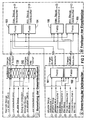
- a fuzzy system is identified by 100 in FIG.
- the data from energy producers, such as individual boilers 51 and 52, which are used to generate steam, and, for example, a turbine 50, which is used to generate electrical energy, are fed into the fuzzy system 100.
- energy producers such as individual boilers 51 and 52, which are used to generate steam, and, for example, a turbine 50, which is used to generate electrical energy
- Other parameters can be entered, which will be discussed in more detail below.
- the fuzzy system 100 is followed by consumers 121, 122 etc.
- the target value M D, 1 being entered here and the current values of the power output being the actual values 1 or their rate of change d / dt are output into the fuzzy system 100.
- average curves for electrical energy consumption e.g.
- the data for electrical energy can either be defined as an average daily curve for total consumption in the existing network or as a factory consumption curve.
- the fuzzy system 100 of FIG. 1 is essentially divided into three blocks: block I provides the evaluation of the overall situation of energy consumption, block II the evaluation of the individual consumers and block III the determination of the individual references.
- block I provides the evaluation of the overall situation of energy consumption
- block II the evaluation of the individual consumers
- block III the determination of the individual references.
- the marked input variables are given to individual fuzzy units 101 to 105 and from there they reach the associated consumers.
- the signal quantities are numbered to clarify the signal flow.
- Block II which can take into account the changing boundary conditions for evaluating the overall situation, is essential in the representation according to FIG.
- the maximum and minimum values of the consumers are given on units 130, 140, which allow the respective membership functions to be compressed or expanded as part of the fuzzification of the input variables.
- the latter is proposed for the general case in the older German patent application P 44 25 674.4 and explained in detail. This can be done online, which should take the changing boundary conditions into account.
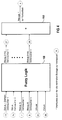
- FIG. 3 shows a fuzzy system 107 in which the status and reference of the individual consumers can be input as input signals.
- the priority of the individual consumers for maximum reference on the one hand and minimum reference on the other hand are output as output signals.
- Such a system can be used in a complex production process, for example in paper production with a large number of individual steps, to determine which production step has the highest priority and is therefore to be operated with an associated energy allocation in each case.
- FIG. 4 shows a fuzzy system 108, into which, in addition to the signals according to FIG. 3, the time of day and the associated date are also fed in as further input variables.
- the output variables for the consumers 1 to n at the time t + t o are given to a summer 150, the result of which defines the necessary energy supply at the lead time.
- fuzzy systems 109, 110 and 111 are available for optimizing the energy generation, which in particular combines the external procurement of energy from other energy supply companies (EVU) with the in-house generation of the existing turbines and the current consumption with reference to the lead time of the individual consumers.
- EEU energy supply companies
- the optimal reference of the power supply company is combined with the generator situation of the existing system as output signals and processed in a unit 150 for load distribution with the existing generators 1 to n.
- the values are calculated with the lead time t + t0, which results in a load distribution reserve.
- rules can be drawn up for connecting the steam generators and the turbines and the electrical power supply from the network.
- the rules for the procurement of electrical energy from third-party networks can access the average day curves of the total energy consumption in the relevant network as information according to FIG. 5.
- information about the expected energy consumption is used. If there are time-cyclic consumption curves for the consumers, these are used for such rules that are used for energy planning. For example, certain energy consumption is in Time intervals are to be expected, whereby the relevant scanning times depend on the start-up time of the energy producers and the necessary shutdown and coordination times for the other consumers.
- the described fuzzy methods can be used with conventional methods to determine the input variables into the fuzzy systems, e.g. Procedure for determining the average curves for electrical energy, i.e. the daily curve, work together.
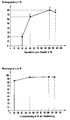
- FIG. 6 shows an effect curve of an individual boiler as an example.
- the efficiency is plotted above the boiler load of the boiler in percent, whereby with 100% boiler load there is naturally a maximum in the performance curve.
- the associated points 1 to 4 were determined for a gas-fired boiler.
- corresponding characteristic curves result when other fossil fuels are used, with the point of use 1 being shifted in each case. For example, for lignite it does not start at 20%, but at 50% efficiency.
- the efficiency of a turbine is usually between 80 and 95%, with an efficiency of 85% already being at 10% turbine output, an efficiency of over 90% being achieved at 50% turbine output, and the maximum in turn is 100%.
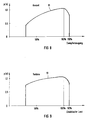
- FIGS. 8 and 9 the so-called fuzzy sets are derived from the characteristic curves of FIGS. 6 and 7, which describe the affiliation to the respective energy generation.
- the graphs 81 and 91 represent membership functions ⁇ (x), which express the degree of truth of the unsharp set in each case.
- the function ⁇ (x) evaluates each element of the set with a real number in the interval between 0 and 1.
- the result is the dependency given in FIGS. 6 and 7 with a constant change now.
- the membership functions ⁇ (x) according to FIGS. 8 and 9 each express a possibility evaluation in terms of content. They differ significantly from the probability assessment in the statistics. With a membership ⁇ (x) defined in this way, the blur can be represented and calculated in a computer. Advantageous applications can be derived in this way especially for energy management according to one of FIGS. 1 to 5.
- the Fuzzy-Petri network is a model concept for operational decision-making processes in complex production systems by using the knowledge of system structure together with the technological experience of the investment experts for the selection of operational control activities.
- Assignments can be defined in a known manner between the process and fuzzy Petri networks, which in particular links the components of the Petri network to the energy distribution system.
- the transitions of the Petri network correspond to certain control operations
- the places of the Petri network correspond to certain work progress provisions
- the branded stream of the Petri network corresponds to the object or material flow
- the flow reaction of the Petri network corresponds to the system structure of any production plant.
- Petri nets are particularly suitable for describing the control operations to be carried out one after the other and in parallel.
- the fuzzy petri network concept thus combines the blurriness of fuzzy technology with the description concept of parallel processes using petri networks.
- FIG. 10 specifically for the modeling of the steam network of an integrated pulp and paper factory:
- the process conditions are illustrated by places, ie circles in the model.
- the entry of electrical energy is controlled by the load controller regulated individual consumers.
- These are the energy system control elements and are represented in the Petri network as transitions that transmit the energy from one producer to one consumer.
- the latter consumption is kept flexible by the controller setting and is therefore specified as the so-called fuzzy switching point of the transitions.
- the fuzzy petri network shown in FIG. 10 is used as a model concept for the steam distribution.
- the parallel and asynchronous valve positions for the steam flows between the generators and consumers are determined depending on the situation.
- the control actions or control element settings with their conditions of use are blurred by transitions (vertical lines) and squares (circles) in the Petri net.
- the availability of the energy producers and the requirements of the consumers describe the process conditions for adjusting the steam flows and are identified by places in the model that are filled with brands according to the consumers. Actuators shown in detail do not serve to change the generation or consumption. This expresses the control options in the energy distribution.
- the latter are described by transitions that transfer the steam from the upstream system to the downstream system in a predetermined ratio. Since the transfer process is flexible, it is also called the unsharp behavior of the transitions. The brand content of the places thus determines the time for changes in the adjacent transitions. The switching of the transitions creates a brand stream between the places, which like the steam flow between the producers, distributors and consumers is transformed from the entrance places to the exit places.
- the membership value 1 describes compliance with the target value and therefore does not require any changes.
- a value less than 1, on the other hand, expresses a deviation from the target value. It has an influence on the control element, but this only reacts if this does not trigger any further deterioration of another subsystem. Such processes can be repeated iteratively.
- LP low-pressure
- HD high-pressure
- a steam accumulator 1030 is connected downstream of the latter and there are a number of consumers 1051 to 1058.
- the respective associated transitions of the fuzzy petri network are shown and designated in detail with 1011 to 1014, 1026, 1027, 1031 to 1038 and 1041 to 1047.
- individual membership functions .mu. (X) are indicated by way of example in the columns of the places indicated in FIG. 10 in the first line.
- the fuzzy petri network enables the system connections and relationships already defined to be made more flexible. Such models can be used with great efficiency in the energy distribution systems described with reference to FIGS. 1 to 5.
- An inference machine is assigned to the fuzzy petri network model. Together with this inference machine, it forms a knowledge-based system.
- the inference machine has been specially developed for the fuzzy petri network.
- the fuzzy petri network itself forms the knowledge base.
- the inference proceeds as follows: Starting from the worst-rated place, the adjacent transitions (settings) are changed until the place is no longer the worst. This is repeated iteratively for all places until the target rating of the network is optimal. The settings of the transitions are switched through to the process and then transfer the network online to the next state. In this new state, the inference cycle starts again.
- the decision behavior of the inference machine is programmed at places and transitions, for example by giving a place a closer membership function and thereby a higher sensitivity, so that other transition settings are triggered during inference.
Landscapes
- Engineering & Computer Science (AREA)
- Artificial Intelligence (AREA)
- Physics & Mathematics (AREA)
- Software Systems (AREA)
- Health & Medical Sciences (AREA)
- Medical Informatics (AREA)
- Mechanical Engineering (AREA)
- Fuzzy Systems (AREA)
- Mathematical Physics (AREA)
- Combustion & Propulsion (AREA)
- Chemical & Material Sciences (AREA)
- Computer Vision & Pattern Recognition (AREA)
- Evolutionary Computation (AREA)
- General Engineering & Computer Science (AREA)
- General Physics & Mathematics (AREA)
- Automation & Control Theory (AREA)
- Management, Administration, Business Operations System, And Electronic Commerce (AREA)
- Engine Equipment That Uses Special Cycles (AREA)
- Feedback Control In General (AREA)
- Radiation-Therapy Devices (AREA)
- Variable-Direction Aerials And Aerial Arrays (AREA)
Applications Claiming Priority (2)
| Application Number | Priority Date | Filing Date | Title |
|---|---|---|---|
| DE4435038A DE4435038A1 (de) | 1994-09-30 | 1994-09-30 | Verfahren zur Energieverteilung in Systemen und zugehörige Anordnung |
| DE4435038 | 1994-09-30 |
Publications (2)
| Publication Number | Publication Date |
|---|---|
| EP0704778A1 true EP0704778A1 (fr) | 1996-04-03 |
| EP0704778B1 EP0704778B1 (fr) | 1999-03-03 |
Family
ID=6529655
Family Applications (1)
| Application Number | Title | Priority Date | Filing Date |
|---|---|---|---|
| EP95115355A Expired - Lifetime EP0704778B1 (fr) | 1994-09-30 | 1995-09-28 | Procédé de distribution d'énergie dans des installations et dispositif pour sa mise en oeuvre |
Country Status (3)
| Country | Link |
|---|---|
| EP (1) | EP0704778B1 (fr) |
| AT (1) | ATE177217T1 (fr) |
| DE (2) | DE4435038A1 (fr) |
Cited By (2)
| Publication number | Priority date | Publication date | Assignee | Title |
|---|---|---|---|---|
| EP1081338A3 (fr) * | 1999-09-03 | 2003-04-23 | Siemens Aktiengesellschaft | Procédé pour le fonctionnement d'une centrale avec au moins un générateur de vapeur et au moins un générateur électrique |
| WO2007000157A3 (fr) * | 2005-06-28 | 2007-04-26 | Maureen Reichelt | Systeme et procede de production d'energie par recyclage des dechets |
Families Citing this family (2)
| Publication number | Priority date | Publication date | Assignee | Title |
|---|---|---|---|---|
| DE10317183B4 (de) * | 2003-04-15 | 2007-04-05 | SWE Strom und Fernwärme GmbH | Temporäre Steigerung durch KWK erzeugter elektrischer Energie |
| AT501847B1 (de) * | 2005-02-02 | 2007-04-15 | Innovative Elektrotechnische P | Verfahren zum erzeugen eines frühindikatorsignals |
Citations (1)
| Publication number | Priority date | Publication date | Assignee | Title |
|---|---|---|---|---|
| JPH05308727A (ja) * | 1992-04-28 | 1993-11-19 | Daioo Eng Kk | 自家発電電力の制御方法 |
-
1994
- 1994-09-30 DE DE4435038A patent/DE4435038A1/de not_active Withdrawn
-
1995
- 1995-09-28 AT AT95115355T patent/ATE177217T1/de not_active IP Right Cessation
- 1995-09-28 EP EP95115355A patent/EP0704778B1/fr not_active Expired - Lifetime
- 1995-09-28 DE DE59505183T patent/DE59505183D1/de not_active Expired - Fee Related
Patent Citations (1)
| Publication number | Priority date | Publication date | Assignee | Title |
|---|---|---|---|---|
| JPH05308727A (ja) * | 1992-04-28 | 1993-11-19 | Daioo Eng Kk | 自家発電電力の制御方法 |
Non-Patent Citations (4)
| Title |
|---|
| BORK P ET AL: "FUZZY CONTROL ZUR OPTIMIERUNG DER KUEHLWASSERAUFBEREITUNG AN EINER CHEMIE-REAKTORANLAGE FUZZY CONTROL OPTIMIZATION OF THE COOLING WATER PREPARATION FOR A CHEMICAL REACTOR PLANT", AUTOMATISIERUNGSTECHNISCHE PRAXIS - ATP, vol. 35, no. 5, 1 May 1993 (1993-05-01), pages 306 - 309, XP000369648 * |
| FUIERER P ET AL: "TAGESEINSATZOPTIMIERUNG FUR KRAFTWERKS-SYSTEME MIT KRAFT-WARME-KOPPLUNG", BWK BRENNSTOFF WARME KRAFT, vol. 41, no. 6, pages 273 - 277, XP000027996 * |
| LIPP H P: "MEHR FLEXIBILITAET DURCH UNSCHAERFE", TECHNISCHE RUNDSCHAU, vol. 85, no. 24, 18 June 1993 (1993-06-18), pages 28 - 33, XP000378570 * |
| PATENT ABSTRACTS OF JAPAN vol. 18, no. 113 (E - 1514) 23 February 1994 (1994-02-23) * |
Cited By (2)
| Publication number | Priority date | Publication date | Assignee | Title |
|---|---|---|---|---|
| EP1081338A3 (fr) * | 1999-09-03 | 2003-04-23 | Siemens Aktiengesellschaft | Procédé pour le fonctionnement d'une centrale avec au moins un générateur de vapeur et au moins un générateur électrique |
| WO2007000157A3 (fr) * | 2005-06-28 | 2007-04-26 | Maureen Reichelt | Systeme et procede de production d'energie par recyclage des dechets |
Also Published As
| Publication number | Publication date |
|---|---|
| DE4435038A1 (de) | 1996-04-04 |
| DE59505183D1 (de) | 1999-04-08 |
| EP0704778B1 (fr) | 1999-03-03 |
| ATE177217T1 (de) | 1999-03-15 |
Similar Documents
| Publication | Publication Date | Title |
|---|---|---|
| DE69520934T2 (de) | Methode und system zur optimierung der nützlichkeit einer anlage | |
| DE19880479B4 (de) | Automatisierungssystem | |
| EP2649567B1 (fr) | Procédée pour la modélisation sur ordinateur d'un système technique | |
| EP2112568B1 (fr) | Procédé de commande et/ou réglage assistées par ordinateur d'un système technique | |
| WO2008080862A1 (fr) | Procédé de régulation et/ou de contrôle assisté par ordinateur d'un système technique, en particulier d'une turbine à gaz | |
| WO2012048808A1 (fr) | Procédé et dispositif d'optimisation d'un processus de production | |
| DE102012216574A1 (de) | Verfahren zur rechnergestützten Steuerung und/oder Regelung eines technischen Systems | |
| DE102018129810A1 (de) | Verfahren und Vorrichtung zur Steuerung einer Anzahl von energieeinspeisenden und/oder energieverbrauchender Einheiten | |
| DE102011106114A1 (de) | Verfahren zur Verteilung von elektrischer Energie in einem Stromnetzwerk mit einer Vielzahl von Verteilungszellen | |
| DE102013224411A1 (de) | Verfahren zur rechnergestützten Konfiguration eines elektrischen Stromnetzes | |
| DE102020204424A1 (de) | Verfahren zur Steuerung eines Wärmenetzes, Steuerungseinheit sowie Wärmeaustauschsystem | |
| WO2018224249A1 (fr) | Procédé pour faire fonctionner une pluralité d'unités techniques en tant qu'ensemble sur un réseau de distribution électrique, ainsi que dispositif de commande et dispositif électrique | |
| WO2007096377A1 (fr) | Régulation prédictive à base de modèle d'une installation de distribution d'énergie d'un bâtiment | |
| DE102018213862A1 (de) | Verfahren zum Steuern eines Austauschs von Energie zwischen Energiesubsystemen zu angeglichenen Konditionen; Steuerungszentrale; Energiesystem; Computerprogramm sowie Speichermedium | |
| EP0704778B1 (fr) | Procédé de distribution d'énergie dans des installations et dispositif pour sa mise en oeuvre | |
| EP1344001B1 (fr) | Procede et dispositif d'exploitation d'une installation technique comportant plusieurs constituants, en particulier d'une installation de combustion destinee a produire de l'energie electrique | |
| EP3323183B1 (fr) | Procédé de commande, assistée par ordinateur, de la puissance dans un réseau de courant électrique | |
| EP0861366B1 (fr) | Procede et dispositif pour la regulation rapide de la production d'une centrale electrique | |
| EP3376026B1 (fr) | Procédé de réglage de la puissance active d'un parc éolien et parc éolien correspondant | |
| EP3985599A1 (fr) | Commande de réseaux énergétiques | |
| WO2025180734A1 (fr) | Procédé de commande de l'utilisation de capacité d'unités d'électrolyse d'un système d'électrolyse | |
| DE112020007149B4 (de) | Zuordnungsunterstützungsprogramm, Zuordnungsunterstützungsvorrichtung, Zuordnungslernprogramm, Zuordnungslernvorrichtung und computerlesbares Speichermedium | |
| WO2023274666A1 (fr) | Procédé et unité de commande permettant de commander une grille thermique | |
| DE102011076969B4 (de) | Verfahren zum rechnergestützten Lernen einer Regelung und/oder Steuerung eines technischen Systems | |
| DE4235274C2 (de) | Verfahren zur Einrichtung und zum Betrieb eines Verbundes von elektrischen Geräten |
Legal Events
| Date | Code | Title | Description |
|---|---|---|---|
| PUAI | Public reference made under article 153(3) epc to a published international application that has entered the european phase |
Free format text: ORIGINAL CODE: 0009012 |
|
| AK | Designated contracting states |
Kind code of ref document: A1 Designated state(s): AT BE CH DE DK ES FR GB GR IE IT LI NL PT SE |
|
| 17P | Request for examination filed |
Effective date: 19960917 |
|
| 17Q | First examination report despatched |
Effective date: 19961128 |
|
| GRAG | Despatch of communication of intention to grant |
Free format text: ORIGINAL CODE: EPIDOS AGRA |
|
| GRAG | Despatch of communication of intention to grant |
Free format text: ORIGINAL CODE: EPIDOS AGRA |
|
| GRAH | Despatch of communication of intention to grant a patent |
Free format text: ORIGINAL CODE: EPIDOS IGRA |
|
| GRAH | Despatch of communication of intention to grant a patent |
Free format text: ORIGINAL CODE: EPIDOS IGRA |
|
| GRAA | (expected) grant |
Free format text: ORIGINAL CODE: 0009210 |
|
| AK | Designated contracting states |
Kind code of ref document: B1 Designated state(s): AT BE CH DE DK ES FR GB GR IE IT LI NL PT SE |
|
| PG25 | Lapsed in a contracting state [announced via postgrant information from national office to epo] |
Ref country code: SE Free format text: THE PATENT HAS BEEN ANNULLED BY A DECISION OF A NATIONAL AUTHORITY Effective date: 19990303 Ref country code: NL Free format text: LAPSE BECAUSE OF FAILURE TO SUBMIT A TRANSLATION OF THE DESCRIPTION OR TO PAY THE FEE WITHIN THE PRESCRIBED TIME-LIMIT Effective date: 19990303 Ref country code: IT Free format text: LAPSE BECAUSE OF FAILURE TO SUBMIT A TRANSLATION OF THE DESCRIPTION OR TO PAY THE FEE WITHIN THE PRE;WARNING: LAPSES OF ITALIAN PATENTS WITH EFFECTIVE DATE BEFORE 2007 MAY HAVE OCCURRED AT ANY TIME BEFORE 2007. THE CORRECT EFFECTIVE DATE MAY BE DIFFERENT FROM THE ONE RECORDED.SCRIBED TIME-LIMIT Effective date: 19990303 Ref country code: GR Free format text: LAPSE BECAUSE OF NON-PAYMENT OF DUE FEES Effective date: 19990303 Ref country code: GB Free format text: LAPSE BECAUSE OF NON-PAYMENT OF DUE FEES Effective date: 19990303 Ref country code: FR Free format text: LAPSE BECAUSE OF FAILURE TO SUBMIT A TRANSLATION OF THE DESCRIPTION OR TO PAY THE FEE WITHIN THE PRESCRIBED TIME-LIMIT Effective date: 19990303 Ref country code: ES Free format text: THE PATENT HAS BEEN ANNULLED BY A DECISION OF A NATIONAL AUTHORITY Effective date: 19990303 |
|
| REF | Corresponds to: |
Ref document number: 177217 Country of ref document: AT Date of ref document: 19990315 Kind code of ref document: T |
|
| REG | Reference to a national code |
Ref country code: CH Ref legal event code: EP |
|
| REG | Reference to a national code |
Ref country code: IE Ref legal event code: FG4D Free format text: GERMAN |
|
| REF | Corresponds to: |
Ref document number: 59505183 Country of ref document: DE Date of ref document: 19990408 |
|
| PG25 | Lapsed in a contracting state [announced via postgrant information from national office to epo] |
Ref country code: DK Free format text: LAPSE BECAUSE OF FAILURE TO SUBMIT A TRANSLATION OF THE DESCRIPTION OR TO PAY THE FEE WITHIN THE PRESCRIBED TIME-LIMIT Effective date: 19990603 |
|
| PG25 | Lapsed in a contracting state [announced via postgrant information from national office to epo] |
Ref country code: PT Free format text: LAPSE BECAUSE OF FAILURE TO SUBMIT A TRANSLATION OF THE DESCRIPTION OR TO PAY THE FEE WITHIN THE PRESCRIBED TIME-LIMIT Effective date: 19990604 |
|
| EN | Fr: translation not filed | ||
| NLV1 | Nl: lapsed or annulled due to failure to fulfill the requirements of art. 29p and 29m of the patents act | ||
| GBV | Gb: ep patent (uk) treated as always having been void in accordance with gb section 77(7)/1977 [no translation filed] |
Effective date: 19990303 |
|
| PG25 | Lapsed in a contracting state [announced via postgrant information from national office to epo] |
Ref country code: AT Free format text: LAPSE BECAUSE OF NON-PAYMENT OF DUE FEES Effective date: 19990928 |
|
| PG25 | Lapsed in a contracting state [announced via postgrant information from national office to epo] |
Ref country code: LI Free format text: LAPSE BECAUSE OF NON-PAYMENT OF DUE FEES Effective date: 19990930 Ref country code: CH Free format text: LAPSE BECAUSE OF NON-PAYMENT OF DUE FEES Effective date: 19990930 Ref country code: BE Free format text: LAPSE BECAUSE OF NON-PAYMENT OF DUE FEES Effective date: 19990930 |
|
| PG25 | Lapsed in a contracting state [announced via postgrant information from national office to epo] |
Ref country code: IE Free format text: LAPSE BECAUSE OF NON-PAYMENT OF DUE FEES Effective date: 19991019 |
|
| REG | Reference to a national code |
Ref country code: IE Ref legal event code: FD4D |
|
| PLBE | No opposition filed within time limit |
Free format text: ORIGINAL CODE: 0009261 |
|
| STAA | Information on the status of an ep patent application or granted ep patent |
Free format text: STATUS: NO OPPOSITION FILED WITHIN TIME LIMIT |
|
| 26N | No opposition filed | ||
| BERE | Be: lapsed |
Owner name: SIEMENS A.G. Effective date: 19990930 |
|
| REG | Reference to a national code |
Ref country code: CH Ref legal event code: PL |
|
| PG25 | Lapsed in a contracting state [announced via postgrant information from national office to epo] |
Ref country code: DE Free format text: LAPSE BECAUSE OF NON-PAYMENT OF DUE FEES Effective date: 20000701 |