EP0704855B1 - Verfahren zur Fertigung von Endstopfen für Kernbrennstäbe - Google Patents
Verfahren zur Fertigung von Endstopfen für Kernbrennstäbe Download PDFInfo
- Publication number
- EP0704855B1 EP0704855B1 EP95306569A EP95306569A EP0704855B1 EP 0704855 B1 EP0704855 B1 EP 0704855B1 EP 95306569 A EP95306569 A EP 95306569A EP 95306569 A EP95306569 A EP 95306569A EP 0704855 B1 EP0704855 B1 EP 0704855B1
- Authority
- EP
- European Patent Office
- Prior art keywords
- blank
- ingot
- flat plate
- longitudinal
- longitudinal axis
- Prior art date
- Legal status (The legal status is an assumption and is not a legal conclusion. Google has not performed a legal analysis and makes no representation as to the accuracy of the status listed.)
- Expired - Lifetime
Links
- 238000000034 method Methods 0.000 title claims description 18
- 239000003758 nuclear fuel Substances 0.000 title claims description 14
- 230000007547 defect Effects 0.000 claims description 44
- 239000000463 material Substances 0.000 claims description 27
- 229910001093 Zr alloy Inorganic materials 0.000 claims description 14
- 238000004519 manufacturing process Methods 0.000 claims description 12
- 238000005098 hot rolling Methods 0.000 claims description 9
- 239000012530 fluid Substances 0.000 claims description 7
- 230000015572 biosynthetic process Effects 0.000 claims description 5
- 238000005242 forging Methods 0.000 claims description 4
- 239000000446 fuel Substances 0.000 description 12
- 238000005253 cladding Methods 0.000 description 9
- 239000001307 helium Substances 0.000 description 8
- 229910052734 helium Inorganic materials 0.000 description 8
- SWQJXJOGLNCZEY-UHFFFAOYSA-N helium atom Chemical compound [He] SWQJXJOGLNCZEY-UHFFFAOYSA-N 0.000 description 8
- 239000008188 pellet Substances 0.000 description 8
- 238000012360 testing method Methods 0.000 description 6
- 239000007788 liquid Substances 0.000 description 5
- 238000003754 machining Methods 0.000 description 5
- 239000007789 gas Substances 0.000 description 4
- 239000002994 raw material Substances 0.000 description 4
- 238000006243 chemical reaction Methods 0.000 description 2
- 230000001066 destructive effect Effects 0.000 description 2
- 208000010228 Erectile Dysfunction Diseases 0.000 description 1
- 238000011109 contamination Methods 0.000 description 1
- 238000001125 extrusion Methods 0.000 description 1
- 239000012467 final product Substances 0.000 description 1
- 238000007689 inspection Methods 0.000 description 1
- 238000010297 mechanical methods and process Methods 0.000 description 1
- 230000005226 mechanical processes and functions Effects 0.000 description 1
- 239000002184 metal Substances 0.000 description 1
- 238000012986 modification Methods 0.000 description 1
- 230000004048 modification Effects 0.000 description 1
- 238000012545 processing Methods 0.000 description 1
- 239000000047 product Substances 0.000 description 1
- 238000012552 review Methods 0.000 description 1
- 238000005096 rolling process Methods 0.000 description 1
- 238000007789 sealing Methods 0.000 description 1
- 238000003466 welding Methods 0.000 description 1
Images
Classifications
-
- G—PHYSICS
- G21—NUCLEAR PHYSICS; NUCLEAR ENGINEERING
- G21C—NUCLEAR REACTORS
- G21C3/00—Reactor fuel elements and their assemblies; Selection of substances for use as reactor fuel elements
- G21C3/02—Fuel elements
- G21C3/04—Constructional details
- G21C3/06—Casings; Jackets
- G21C3/10—End closures ; Means for tight mounting therefor
-
- Y—GENERAL TAGGING OF NEW TECHNOLOGICAL DEVELOPMENTS; GENERAL TAGGING OF CROSS-SECTIONAL TECHNOLOGIES SPANNING OVER SEVERAL SECTIONS OF THE IPC; TECHNICAL SUBJECTS COVERED BY FORMER USPC CROSS-REFERENCE ART COLLECTIONS [XRACs] AND DIGESTS
- Y02—TECHNOLOGIES OR APPLICATIONS FOR MITIGATION OR ADAPTATION AGAINST CLIMATE CHANGE
- Y02E—REDUCTION OF GREENHOUSE GAS [GHG] EMISSIONS, RELATED TO ENERGY GENERATION, TRANSMISSION OR DISTRIBUTION
- Y02E30/00—Energy generation of nuclear origin
- Y02E30/30—Nuclear fission reactors
Definitions
- the present invention relates generally to methods for fabricating end plugs for nuclear fuel rods and particularly to fabrication methods wherein gas leakage paths through the end plugs resultant from internal material defects are reduced and/or the defects are rendered ineffective to produce fluid leakage paths, e.g., either gas or liquid.
- Nuclear fuel rods for nuclear reactors typically comprise a plurality of discrete nuclear fuel pellets disposed within a Zircaloy cladding tube.
- the pellets are stacked within the cladding tube which is then evacuated, back-filled with helium and sealed by welding Zircaloy end plugs at each of the opposite ends of the tube.
- Typical Zircaloy cladding tubes may have outside diameters, for example, on the order of 10-13 mm (0.4-0.5 inches) and lengths on the order of 3.8-4.1 m (150-160 inches).
- the end plugs per se depending on whether they are upper or lower end plugs in use, may have a length of approximately 3-1/2 inches or smaller and a diameter substantially approximating the diameter of the fuel rod cladding
- the Zircaloy material from which the end plugs are formed initially comprises a large diameter ingot, e.g., on the order of 0.91 m (36 inches).
- the ingot is reduced down from such large diameter to barstock size, for example, barstock approximating between about 6.3 and 19.0 mm (0.25 and 0.75 inches).
- These thermal and mechanical operations include a substantial number of labor-intensive and costly steps such as a series of forging and reforging operations, extrusions and swaging with reheat therebetween.
- This reduced barstock is normally provided in random, but long, lengths, on the order of several meters (many feet).
- machining operations are performed directly on the barstock to finally shape the end plugs.
- the barstock is fed through a chuck on a screw machine and machined directly to the final shape of the end plug.
- small pieces or blanks can be preformed, e.g., by a forging operation, and the final end plugs formed by a chucking machine.
- non-destructive tests Prior to forming the end plugs from the barstock material, non-destructive tests are typically performed on the barstock in order to detect and remove internal defects which are a result of and inherent to the previously described thermal and mechanical operations necessary to reduce the ingot from its large diameter to barstock size. Internal defects may also arise on occasion as a result of using contaminated materials, including recycle material.
- These non-destructive tests may include ultrasonic tests, metallographic tests on the barstock ends or liquid penetrant inspection on the ends of the bars. The purpose of the tests is to detect and identify defects which might provide leakage paths for gas or liquids within the fuel rod cladding once the plugs are welded to the cladding and the fuel rods are charged with helium.
- the reducing operations typically require a large number of thermal and mechanical operations, as previously described. Those operations require substantial time and labor. Hence, the processing becomes time-consuming, expensive and incurs material loss.
- a method according to claim 1 for forming the end plugs for nuclear fuel rods in a manner which reduces or eliminates centerline defects in the material and leakage paths in the final end plug product there is provided a method according to claim 1 for forming the end plugs for nuclear fuel rods in a manner which reduces or eliminates centerline defects in the material and leakage paths in the final end plug product.
- centerline defects does not mean defects limited to the centerline or axis of the material but embraces defects extending in a longitudinal direction not necessarily on the axis of the material.
- the invention employs a different form, e.g., a flat plate, of the same Zircaloy raw material used previously to form end plugs and from which flat plate blanks for the end plugs are formed and subsequently machined to final shape.
- the invention also uses a different orientation of the blank relative to any centerline defects formed in the plate whereby any such defects are rendered ineffective as leakage paths in the final end plugs. That is, the occurrence of internal centerline defects in the Zircaloy material is substantially reduced by the present manufacturing method and, additionally, should any such defect occur when the end plugs are manufactured in accordance with the present invention, the defect will be oriented in a different direction which effectively eliminates the defect as a potential leakage path in the end plugs.
- end plug leakage paths are substantially a result of the previously utilized ingot-reducing operations, the centerline defects necessarily inherent from those reducing operations and/or material contamination.
- the present invention employs a reducing operation which minimizes the occurrence of centerline defects and which orients such defects, should they occur, in a manner which eliminates the defects as leakage paths.
- the ingot is mechanically formed into rolling stock, then rolled into a flat plate, for example, by hot-rolling. It has been found that flat plate material has fewer longitudinal defects of the type which might form leakage paths when subsequently shaped to form end plugs.
- the blanks from the flat plate material which ultimately will be finished to form the end plugs, are taken from the flat plate in one of two directions transverse to the extension of the material as it is converted from the ingot to flat plate. That is to say, the Zircaloy ingot is formed, preferably by hot-rolling, into an elongated flat plate having length, width and thickness dimensions.
- a blank is formed from the plate having a long axis, eventually corresponding to the long axis of the end plug, and which long axis extends perpendicular to the longitudinal or thickness dimensions of the plate.
- the longitudinal axis of the end plug lies transverse to any centerline defects that exist in the flat plate material.
- any internal defects arrayed in the longitudinal direction of the raw material will lie in the finished end plugs in an impotent, transverse direction of the end plug effectively precluding a centerline defect from forming a helium or a liquid leak path end-to-end through the end plug.
- An additional benefit from the foregoing-described process is realized in that the conversion of the Zircaloy ingot to the flat plate is less labor intensive and costly than the conversion of the ingot to the small-diameter barstock in the processes previously utilized.
- a method of manufacturing end plugs for nuclear fuel rods wherein defects potentially forming leakage paths through the end plugs are minimized, eliminated or rendered ineffective comprising the steps of forming an ingot of a Zircaloy material into a flat plate having longitudinal and transverse dimensions, forming an elongated blank from the flat plate with a longitudinal dimension of the blank lying generally perpendicular to the longitudinal dimension of the plate and finishing the blank to form an end plug having a longitudinal axis generally parallel with the longitudinal dimension of the blank.
- a method of manufacturing end plugs for nuclear fuel rods wherein defects potentially forming leakage paths through the end plugs are minimized, eliminated or rendered ineffective comprising the steps of hot-rolling an ingot of a Zircaloy material into a flat plate having longitudinal, transverse and thickness dimensions, forming an elongated blank from the flat plate, the blank having a longitudinal axis lying generally perpendicular to one of the longitudinal and thickness dimensions of the plate and machining the blank to form an end plug having a longitudinal axis generally coincident with the longitudinal axis of the blank.
- a method of manufacturing end plugs for nuclear fuel rods wherein defects potentially forming fluid leakage paths through the end plugs are minimized, eliminated or rendered ineffective comprising the steps of forming an ingot of a Zircaloy material into a flat plate having a material extension direction resultant from the formation of the ingot into the flat plate, forming an elongated blank from the flat plate, the blank having a longitudinal axis lying generally perpendicular to the direction of material extension resultant from the formation of the ingot into the flat plate and machining the blank to form an end plug having a longitudinal axis generally coincident with the longitudinal axis of the blank.
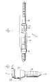
- a nuclear fuel rod assembly generally designated 10 comprised of a plurality of nuclear fuel pellets 12, for example, formed of UO 2 disposed within a thin walled cladding tube 14.
- the pellets 12 are stacked one on top of the other in the tube 14 and lower and upper end plugs 16 and 18, respectively, are typically welded to the lower and upper ends of the tube, respectively, to seal the tube.
- the tube 14 with pellets 12 therein Prior to sealing the ends of the tube, the tube 14 with pellets 12 therein is evacuated and back-filled with helium, the helium being sealed within the tube by the end plugs 16 and 18.
- a spring 20 is provided in a plenum 21 at the upper end of the tube to exert a downward force on the pellets 12 to maintain the pellets in place during handling procedures.
- a very small gap is provided between the outer diameter of the pellets and the inner wall surface of the cladding tube.
- the fuel rod 10 illustrated in FIGURE 1 is typically used in an array of fuel rods, for example, an 8x8 or 9x9 array to form a nuclear fuel bundle.
- the bundle is in turn located between lower and upper tie plates, not shown.
- the lower end plugs are received in openings in the lower tie plate grid and typically an expansion spring is located over the top end plug to maintain the fuel rods of the bundle seated in the lower tie plate.
- lower end plug 16 is illustrated and includes a body portion 22 having a projecting end pin or shaft 24 which may be threaded, a flange 26 about the opposite end, and a reduced boss 27 at such opposite end for disposition within the cladding 14.
- the lower end plug has a central longitudinal axis along the line A-A in FIGURE 2. It will be appreciated that the lower end plug 16, is disposed in the lower end of the tubing 14 with the flange 26 butting the tubing end and welded thereto to seal the lower end of the fuel rod 10.
- FIGURE 3 a representative example of an upper end plug 18 is illustrated and has an elongated body about a longitudinal axis B-B in FIGURE 3. The lower end of the upper plug 18 terminates in a flange 28 and a reduced boss 29. It will be appreciated that the flange and upper end of the tubing are welded one to the other with the plug projecting from the tubing.
- FIGURE 4 there is illustrated a representative example of barstock 30 which has been reduced from a larger ingot size, for example, on the order of 660-762 mm (26-30 inches) in diameter to a size just larger than or approximating the diameter of the end plugs to be formed from the barstock, for example, within a range of 6.3 to 19.0 mm (.25 and .75 inches) in diameter
- the barstock has inherent typically longitudinally extending defects, mostly near the centerline.
- the dashed lines 32 in FIGURE 4 are representative of the centerline defects. It will be appreciated that the defects are of microscopic size and cannot be accurately illustrated in a drawing of this scale.
- this is accomplished by employing a different form of the same raw material previously used to form end plugs to form blanks from which the present end plugs are ultimately formed, for example, by machining.
- the present invention (i) reduces or eliminates the occurrence of centerline defects in the end plugs, (ii) orients any defects in the end plugs in a manner which is not susceptible or conductive to the formation of centerline fluid leakage paths (which might permit helium gas to escape from the rod or liquid to enter the rod) and (iii) reduces the labor and cost involved in the fabrication of the end plugs.
- the ingot of raw material for example, Zircaloy
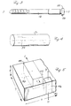
- the ingot of raw material is formed, preferably by hot-rolling, into an elongated flat plate configuration, for example, the plate 40 partially illustrated in FIGURE 5.
- plate 40 has longitudinal, transverse and thickness dimensions x , y and z , respectively.
- a blank 44 which will ultimately form an end plug, is formed in plate 40 with an axial direction C-C of the blank corresponding in direction to the axis A-A or B-B of the final machined end plug.
- blank 44 illustrated in FIGURE 5 may be machined, cropped, stamped or cut from the plate 40 in a transverse direction y whereby the axis C-C of the blank is generally orthogonally related to the longitudinal and thickness dimensions x and z and generally parallel to the transverse direction y of the flat plate 40.
- a blank 46 may be machined, cropped, stamped or cut from plate 40 in a direction such that the axis D-D of the blank is generally parallel to the thickness dimension z and orthogonal and transverse directions x and y , respectively.
- any defects in the ingot will appear in the longitudinal dimension x , as illustrated by the dashed lines 42 and 43. Consequently, the likelihood of a centerline defect appearing in a direction which would produce a fluid leakage path in the final end plug is reduced.
- any such defect exists in the final product, it extends generally transversely of the end plug and not longitudinally thereof and thus is generally not available to form a leakage path between opposite ends of the end plug.
- the blank may be machined to the final end plug configuration.
- the axis of the end plug either A-A or B-B, will, of course, lie coincident with or parallel to the axis C-C of the blank 44 taken from plate 40 or the axis D-D of the blank 46 taken from the plate 40.
- the blanks may, of course, be taken from the flat plate at angles other than orthogonal angles provided only that the centerline of the end plug is generally perpendicular to the direction of material extension when forming the plate.
Landscapes
- Physics & Mathematics (AREA)
- Engineering & Computer Science (AREA)
- Plasma & Fusion (AREA)
- General Engineering & Computer Science (AREA)
- High Energy & Nuclear Physics (AREA)
- Forging (AREA)
- Monitoring And Testing Of Nuclear Reactors (AREA)
Claims (9)
- Verfahren zum Fertigen von Endstopfen (16,18) für Kernbrennstoffstäbe (10), bei denen Defekte, die möglicherweise Fluidleckagepfade durch die Endstopfen (16,18) bilden, minimiert, eliminiert oder unwirksam gemacht sind, enthaltend die Schritte:Formen eines Rohblockes aus einem Zircaloy-Material zu einer ebenen Platte (40), die eine Materialverlaufsrichtung (X) hat, die aus der Formung des Rohblockes zu der ebenen Platte (40) resultiert,Formen eines langgestreckten Rohlings (40;46) aus der ebenen Platte (40), wobei der Rohling (40;46) eine Längsachse (C-C; D-D) hat, die im wesentlichen senkrecht zu der Richtung des Materialverlaufs (X) liegt, die aus der Formung des Rohblockes zu der ebenen Platte (40) resultiert, undEndbearbeiten des Rohlings (40;46) zum Formen eines Endstopfens (16,18) mit einer Längsachse, die im wesentlichen mit der Längsachse (C-C; D-D) des Rohlings zusammenfällt.
- Verfahren nach Anspruch 1, wobei der Schritt zum Formen der ebenen Platte (40) enthält, daß der Rohblock in einer Walzrichtung entsprechend der Richtung des Materialverlaufs (X) warmgewalzt wird.
- Verfahren nach Anspruch 1, wobei der Rohblock Längs- und Querabmessungen (X,Y) hat, wobei der langgestreckte Rohling (44) eine Längsabmessung (C-C) hat, die im wesentlichen senkrecht zu der Längsabmessung (X) der Platte (40) liegt, und wobei der Rohling (44) endbearbeitet wird zur Bildung eines Endstopfens (16,18) mit einer Längsachse, die im wesentlichen parallel zu der Längsabmessung (C-C) des Rohlings (44) ist.
- Verfahren nach einem der Ansprüche 1 bis 3, wobei der Rohblock mit Wärme und Druck beaufschlagt wird, um die ebene Platte (40) zu erzeugen.
- Verfahren nach Anspruch 3, wobei die Platte (40) orthogonal in Beziehung stehende Längs-, Quer- und Dickenabmessungen (X,Y,Z) hat, und wobei der Schritt vorgesehen ist, daß der Rohling so aus der ebenen Platte (40) geformt wird, daß eine Längsachse (D-D) des Rohlings (46) im wesentlichen parallel zu der Dickenabmessung (Z) der Platte (40) liegt.
- Verfahren nach Anspruch 3, wobei die Platte orthogonal in Beziehung stehende Längs- Quer- und Dickenabmessungen (X,Y,Z) hat, und wobei der Schritt vorgesehen ist, daß der Rohling (44) so aus der ebenen Platte (40) geformt wird, daß eine Längsachse (C-C) des Rohlings (44) im wesentlichen parallel zu der Querabmessung (Y) der Platte (40) liegt.
- Verfahren nach Anspruch 3, wobei der Rohling warmgewalzt wird, um die ebene Platte (40) zu erzeugen, wobei der Rohling (44) so geformt wird, daß seine Längsachse (C-C) quer zu der Walzenrichtung liegt, wenn der Rohblock warmgewalzt wird.
- Verfahren nach Anspruch 3, wobei der Schritt der Endbearbeitung ein mechanisches Formen enthält, wie beispielsweise Verjüngen, Drehschmieden oder Gesenkschmieden, um dem Rohling (40) Profil zu geben und den Endstopfen (16,18) zu formen.
- Verfahren nach Anspruch 1, wobei der Rohblock zu einer ebenen Platte (40) mit Längs-, Quer- und Dickenabmessungen (X,Y,Z) warmgewalzt wird, wobei der langgestreckte Rohling (44) eine Längsachse (C-C) hat, die im wesentlichen senkrecht zu einer der Längs- und Dickenabmessungen (X,Z) der Platte (40) liegt, und wobei der Rohling (44) bearbeitet wird, um einen Endstopfen (16,18) mit einer Längsachse zu formen, die mit der Längsachse (C-C) des Rohlings im wesentlichen zusammenfällt.
Applications Claiming Priority (2)
| Application Number | Priority Date | Filing Date | Title |
|---|---|---|---|
| US313604 | 1994-09-29 | ||
| US08/313,604 US5966980A (en) | 1994-09-29 | 1994-09-29 | Method for fabricating end plugs for nuclear fuel rods |
Publications (2)
| Publication Number | Publication Date |
|---|---|
| EP0704855A1 EP0704855A1 (de) | 1996-04-03 |
| EP0704855B1 true EP0704855B1 (de) | 1999-01-13 |
Family
ID=23216387
Family Applications (1)
| Application Number | Title | Priority Date | Filing Date |
|---|---|---|---|
| EP95306569A Expired - Lifetime EP0704855B1 (de) | 1994-09-29 | 1995-09-18 | Verfahren zur Fertigung von Endstopfen für Kernbrennstäbe |
Country Status (4)
| Country | Link |
|---|---|
| US (1) | US5966980A (de) |
| EP (1) | EP0704855B1 (de) |
| JP (1) | JPH08211174A (de) |
| DE (1) | DE69507238T2 (de) |
Families Citing this family (2)
| Publication number | Priority date | Publication date | Assignee | Title |
|---|---|---|---|---|
| US5748691A (en) * | 1996-03-11 | 1998-05-05 | General Electric Company | Apparatus and methods for sealing end plugs for nuclear fuel rods |
| CN111554422B (zh) * | 2020-04-10 | 2022-09-16 | 中核北方核燃料元件有限公司 | 一种消除焊缝气胀缺陷的端塞 |
Family Cites Families (8)
| Publication number | Priority date | Publication date | Assignee | Title |
|---|---|---|---|---|
| BE724655A (de) * | 1968-11-29 | 1969-05-02 | ||
| US3804708A (en) * | 1971-11-24 | 1974-04-16 | United Nuclear Corp | Nuclear reactor fuel rod |
| GB1404234A (en) * | 1972-09-15 | 1975-08-28 | Atomic Energy Authority Uk | Plugs |
| BE818879A (fr) * | 1974-08-14 | 1974-12-02 | Bouchon destine a la fermeture d'un gainage et procede de fabrication d'un tel bouchon | |
| FR2575762B1 (fr) * | 1985-01-10 | 1989-03-03 | Fragema Framatome & Cogema | Procede de fabrication de plaquettes en alliage de zirconium |
| US4751045A (en) * | 1985-10-22 | 1988-06-14 | Westinghouse Electric Corp. | PCI resistant light water reactor fuel cladding |
| SU1697966A1 (ru) * | 1989-08-22 | 1991-12-15 | Производственное объединение "Ижорский завод" | Способ получени заготовок дисков |
| US5069865A (en) * | 1990-12-14 | 1991-12-03 | Westinghouse Electric Corp. | Method of forming a gripper cavity in a fuel rod end plug |
-
1994
- 1994-09-29 US US08/313,604 patent/US5966980A/en not_active Expired - Fee Related
-
1995
- 1995-09-18 EP EP95306569A patent/EP0704855B1/de not_active Expired - Lifetime
- 1995-09-18 DE DE69507238T patent/DE69507238T2/de not_active Expired - Fee Related
- 1995-09-26 JP JP7247102A patent/JPH08211174A/ja active Pending
Also Published As
| Publication number | Publication date |
|---|---|
| DE69507238T2 (de) | 1999-07-29 |
| US5966980A (en) | 1999-10-19 |
| JPH08211174A (ja) | 1996-08-20 |
| EP0704855A1 (de) | 1996-04-03 |
| DE69507238D1 (de) | 1999-02-25 |
Similar Documents
| Publication | Publication Date | Title |
|---|---|---|
| US6411668B1 (en) | Guide tube of a nuclear reactor fuel assembly | |
| EP0695598B1 (de) | Herstellungsverfahren von Durchgangsverbindungen zwischen Rohren aus verschiedenen Metallen | |
| EP0704855B1 (de) | Verfahren zur Fertigung von Endstopfen für Kernbrennstäbe | |
| CN113021005B (zh) | 一种大口径不锈钢直缝焊管连续智能成形装置 | |
| US4579087A (en) | Corrosion resistant steam generator and method of making same | |
| CN221870058U (zh) | 卷制高精度厚壁筒体用的辅助工装 | |
| US4728491A (en) | Cladding tube of a zirconium alloy especially for a nuclear reactor fuel rod and method for fabricating the cladding tube | |
| EP1025920B1 (de) | Verfahren zur Herstellung eines mehrschichtigen dünnwandigen Balges aus rostfreiem Stahl | |
| JPH05208203A (ja) | 継目無クラッド金属管の製造方法 | |
| JPH07136711A (ja) | クラッド鋼管製造用2重素管の製造方法 | |
| JPH08243680A (ja) | 管のアプセット加工方法 | |
| CN114346623B (zh) | 一种波纹管补偿器制造成型加工工艺 | |
| SU786865A3 (ru) | Способ изготовлени прецизионных труб | |
| US4631167A (en) | Method for the production of a nuclear reactor assembly and assembly obtained by this method | |
| CN117840547B (zh) | 厚壁奥氏体不锈钢管道和20MnMo钢管道的焊接工艺 | |
| CN116586902B (zh) | 一种新型定尺伸缩式承插型盘扣脚手架加工工艺 | |
| US5574761A (en) | Fuel channels with off-centerline welds | |
| CN120244155A (zh) | 一种大型列管式换热器管子-管板低应力焊胀成型方法 | |
| CN117564628A (zh) | 一种高精度厚壁筒体成形方法及辅助工装 | |
| Rose et al. | Zircaloy cladding tubes: Manufacturing techniques and achievable quality—A tube manufacturer's view | |
| JPS59191516A (ja) | 厚肉大径鋼管の製造方法 | |
| SU1571864A1 (ru) | Способ изготовлени вольфрамовых труб | |
| JPS63249050A (ja) | 電気抵抗溶接管製造時の非破壊検査法 | |
| SU1230712A1 (ru) | Способ производства двухшовных сварных труб большого диаметра | |
| KR20240130761A (ko) | 강관, 강관군, 파이프라인, 및 강관 제조 방법 |
Legal Events
| Date | Code | Title | Description |
|---|---|---|---|
| PUAI | Public reference made under article 153(3) epc to a published international application that has entered the european phase |
Free format text: ORIGINAL CODE: 0009012 |
|
| AK | Designated contracting states |
Kind code of ref document: A1 Designated state(s): CH DE ES LI SE |
|
| 17P | Request for examination filed |
Effective date: 19961004 |
|
| 17Q | First examination report despatched |
Effective date: 19970714 |
|
| GRAG | Despatch of communication of intention to grant |
Free format text: ORIGINAL CODE: EPIDOS AGRA |
|
| GRAG | Despatch of communication of intention to grant |
Free format text: ORIGINAL CODE: EPIDOS AGRA |
|
| GRAH | Despatch of communication of intention to grant a patent |
Free format text: ORIGINAL CODE: EPIDOS IGRA |
|
| GRAH | Despatch of communication of intention to grant a patent |
Free format text: ORIGINAL CODE: EPIDOS IGRA |
|
| GRAA | (expected) grant |
Free format text: ORIGINAL CODE: 0009210 |
|
| AK | Designated contracting states |
Kind code of ref document: B1 Designated state(s): CH DE ES LI SE |
|
| PG25 | Lapsed in a contracting state [announced via postgrant information from national office to epo] |
Ref country code: LI Free format text: LAPSE BECAUSE OF FAILURE TO SUBMIT A TRANSLATION OF THE DESCRIPTION OR TO PAY THE FEE WITHIN THE PRESCRIBED TIME-LIMIT Effective date: 19990113 Ref country code: ES Free format text: THE PATENT HAS BEEN ANNULLED BY A DECISION OF A NATIONAL AUTHORITY Effective date: 19990113 Ref country code: CH Free format text: LAPSE BECAUSE OF FAILURE TO SUBMIT A TRANSLATION OF THE DESCRIPTION OR TO PAY THE FEE WITHIN THE PRESCRIBED TIME-LIMIT Effective date: 19990113 |
|
| REG | Reference to a national code |
Ref country code: CH Ref legal event code: EP |
|
| REF | Corresponds to: |
Ref document number: 69507238 Country of ref document: DE Date of ref document: 19990225 |
|
| REG | Reference to a national code |
Ref country code: CH Ref legal event code: PL |
|
| PLBE | No opposition filed within time limit |
Free format text: ORIGINAL CODE: 0009261 |
|
| STAA | Information on the status of an ep patent application or granted ep patent |
Free format text: STATUS: NO OPPOSITION FILED WITHIN TIME LIMIT |
|
| 26N | No opposition filed | ||
| PGFP | Annual fee paid to national office [announced via postgrant information from national office to epo] |
Ref country code: SE Payment date: 20020903 Year of fee payment: 8 |
|
| PGFP | Annual fee paid to national office [announced via postgrant information from national office to epo] |
Ref country code: DE Payment date: 20020930 Year of fee payment: 8 |
|
| PG25 | Lapsed in a contracting state [announced via postgrant information from national office to epo] |
Ref country code: SE Free format text: LAPSE BECAUSE OF NON-PAYMENT OF DUE FEES Effective date: 20030919 |
|
| PG25 | Lapsed in a contracting state [announced via postgrant information from national office to epo] |
Ref country code: DE Free format text: LAPSE BECAUSE OF NON-PAYMENT OF DUE FEES Effective date: 20040401 |
|
| EUG | Se: european patent has lapsed |