EP0704862A2 - Supraleitender Draht und dessen Herstellungsverfahren - Google Patents
Supraleitender Draht und dessen Herstellungsverfahren Download PDFInfo
- Publication number
- EP0704862A2 EP0704862A2 EP95306444A EP95306444A EP0704862A2 EP 0704862 A2 EP0704862 A2 EP 0704862A2 EP 95306444 A EP95306444 A EP 95306444A EP 95306444 A EP95306444 A EP 95306444A EP 0704862 A2 EP0704862 A2 EP 0704862A2
- Authority
- EP
- European Patent Office
- Prior art keywords
- superconducting wire
- oxide superconductor
- silver
- wire according
- manufacturing
- Prior art date
- Legal status (The legal status is an assumption and is not a legal conclusion. Google has not performed a legal analysis and makes no representation as to the accuracy of the status listed.)
- Granted
Links
- 238000004519 manufacturing process Methods 0.000 title claims abstract description 38
- 239000002887 superconductor Substances 0.000 claims abstract description 149
- 239000004020 conductor Substances 0.000 claims abstract description 60
- 238000010438 heat treatment Methods 0.000 claims abstract description 55
- 229910052751 metal Inorganic materials 0.000 claims abstract description 50
- 239000002184 metal Substances 0.000 claims abstract description 49
- 238000000034 method Methods 0.000 claims abstract description 38
- 230000008018 melting Effects 0.000 claims abstract description 25
- 238000002844 melting Methods 0.000 claims abstract description 25
- 239000007769 metal material Substances 0.000 claims abstract description 20
- BQCADISMDOOEFD-UHFFFAOYSA-N Silver Chemical compound [Ag] BQCADISMDOOEFD-UHFFFAOYSA-N 0.000 claims description 87
- 229910052709 silver Inorganic materials 0.000 claims description 85
- 239000004332 silver Substances 0.000 claims description 85
- 239000000463 material Substances 0.000 claims description 62
- 229910001316 Ag alloy Inorganic materials 0.000 claims description 43
- 229910052802 copper Inorganic materials 0.000 claims description 23
- 239000000155 melt Substances 0.000 claims description 21
- 229910052760 oxygen Inorganic materials 0.000 claims description 21
- 229910052737 gold Inorganic materials 0.000 claims description 14
- 239000000203 mixture Substances 0.000 claims description 12
- 229910052782 aluminium Inorganic materials 0.000 claims description 10
- 229910052763 palladium Inorganic materials 0.000 claims description 10
- 229910052719 titanium Inorganic materials 0.000 claims description 10
- 229910052747 lanthanoid Inorganic materials 0.000 claims description 8
- 150000002602 lanthanoids Chemical class 0.000 claims description 8
- 229910052721 tungsten Inorganic materials 0.000 claims description 6
- 229910052750 molybdenum Inorganic materials 0.000 claims description 4
- 229910052702 rhenium Inorganic materials 0.000 claims description 4
- 229910052720 vanadium Inorganic materials 0.000 claims description 4
- 229910045601 alloy Inorganic materials 0.000 claims description 3
- 239000000956 alloy Substances 0.000 claims description 3
- 229910052727 yttrium Inorganic materials 0.000 claims description 3
- 229910052684 Cerium Inorganic materials 0.000 claims description 2
- 229910052692 Dysprosium Inorganic materials 0.000 claims description 2
- 229910052691 Erbium Inorganic materials 0.000 claims description 2
- 229910052693 Europium Inorganic materials 0.000 claims description 2
- 229910052688 Gadolinium Inorganic materials 0.000 claims description 2
- 229910052689 Holmium Inorganic materials 0.000 claims description 2
- 229910052765 Lutetium Inorganic materials 0.000 claims description 2
- 229910052779 Neodymium Inorganic materials 0.000 claims description 2
- 229910052777 Praseodymium Inorganic materials 0.000 claims description 2
- 229910052772 Samarium Inorganic materials 0.000 claims description 2
- 229910052771 Terbium Inorganic materials 0.000 claims description 2
- 229910052775 Thulium Inorganic materials 0.000 claims description 2
- 229910052769 Ytterbium Inorganic materials 0.000 claims description 2
- 229910052788 barium Inorganic materials 0.000 claims description 2
- 229910052791 calcium Inorganic materials 0.000 claims description 2
- 238000006243 chemical reaction Methods 0.000 claims description 2
- 229910052733 gallium Inorganic materials 0.000 claims description 2
- 229910052732 germanium Inorganic materials 0.000 claims description 2
- 229910052742 iron Inorganic materials 0.000 claims description 2
- 229910052746 lanthanum Inorganic materials 0.000 claims description 2
- 229910052748 manganese Inorganic materials 0.000 claims description 2
- 229910052759 nickel Inorganic materials 0.000 claims description 2
- 229910052758 niobium Inorganic materials 0.000 claims description 2
- 229910052697 platinum Inorganic materials 0.000 claims description 2
- 229910052712 strontium Inorganic materials 0.000 claims description 2
- 239000011248 coating agent Substances 0.000 claims 1
- 238000000576 coating method Methods 0.000 claims 1
- 239000010949 copper Substances 0.000 description 23
- RYGMFSIKBFXOCR-UHFFFAOYSA-N Copper Chemical compound [Cu] RYGMFSIKBFXOCR-UHFFFAOYSA-N 0.000 description 17
- KDLHZDBZIXYQEI-UHFFFAOYSA-N palladium Substances [Pd] KDLHZDBZIXYQEI-UHFFFAOYSA-N 0.000 description 17
- 238000005491 wire drawing Methods 0.000 description 16
- QVGXLLKOCUKJST-UHFFFAOYSA-N atomic oxygen Chemical compound [O] QVGXLLKOCUKJST-UHFFFAOYSA-N 0.000 description 15
- 239000001301 oxygen Substances 0.000 description 15
- 239000010931 gold Substances 0.000 description 13
- PCHJSUWPFVWCPO-UHFFFAOYSA-N gold Chemical compound [Au] PCHJSUWPFVWCPO-UHFFFAOYSA-N 0.000 description 12
- 238000010586 diagram Methods 0.000 description 11
- 239000010409 thin film Substances 0.000 description 11
- 238000004804 winding Methods 0.000 description 11
- XAGFODPZIPBFFR-UHFFFAOYSA-N aluminium Chemical compound [Al] XAGFODPZIPBFFR-UHFFFAOYSA-N 0.000 description 8
- 239000000843 powder Substances 0.000 description 7
- 239000007789 gas Substances 0.000 description 6
- CURLTUGMZLYLDI-UHFFFAOYSA-N Carbon dioxide Chemical compound O=C=O CURLTUGMZLYLDI-UHFFFAOYSA-N 0.000 description 4
- 239000013078 crystal Substances 0.000 description 4
- 230000003247 decreasing effect Effects 0.000 description 4
- 238000005096 rolling process Methods 0.000 description 4
- 230000000087 stabilizing effect Effects 0.000 description 4
- 239000000758 substrate Substances 0.000 description 3
- IJGRMHOSHXDMSA-UHFFFAOYSA-N Atomic nitrogen Chemical compound N#N IJGRMHOSHXDMSA-UHFFFAOYSA-N 0.000 description 2
- BVKZGUZCCUSVTD-UHFFFAOYSA-L Carbonate Chemical compound [O-]C([O-])=O BVKZGUZCCUSVTD-UHFFFAOYSA-L 0.000 description 2
- FYYHWMGAXLPEAU-UHFFFAOYSA-N Magnesium Chemical compound [Mg] FYYHWMGAXLPEAU-UHFFFAOYSA-N 0.000 description 2
- 229910002651 NO3 Inorganic materials 0.000 description 2
- NHNBFGGVMKEFGY-UHFFFAOYSA-N Nitrate Chemical compound [O-][N+]([O-])=O NHNBFGGVMKEFGY-UHFFFAOYSA-N 0.000 description 2
- 229910002092 carbon dioxide Inorganic materials 0.000 description 2
- 239000001569 carbon dioxide Substances 0.000 description 2
- 239000000470 constituent Substances 0.000 description 2
- 238000005336 cracking Methods 0.000 description 2
- 239000010408 film Substances 0.000 description 2
- 239000012535 impurity Substances 0.000 description 2
- 229910000953 kanthal Inorganic materials 0.000 description 2
- 229910052749 magnesium Inorganic materials 0.000 description 2
- 239000011777 magnesium Substances 0.000 description 2
- 238000007711 solidification Methods 0.000 description 2
- 230000008023 solidification Effects 0.000 description 2
- 239000003381 stabilizer Substances 0.000 description 2
- LEDMRZGFZIAGGB-UHFFFAOYSA-L strontium carbonate Chemical compound [Sr+2].[O-]C([O-])=O LEDMRZGFZIAGGB-UHFFFAOYSA-L 0.000 description 2
- 229910000018 strontium carbonate Inorganic materials 0.000 description 2
- ZLHLYESIHSHXGM-UHFFFAOYSA-N 4,6-dimethyl-1h-imidazo[1,2-a]purin-9-one Chemical compound N=1C(C)=CN(C2=O)C=1N(C)C1=C2NC=N1 ZLHLYESIHSHXGM-UHFFFAOYSA-N 0.000 description 1
- 229910000881 Cu alloy Inorganic materials 0.000 description 1
- 230000015572 biosynthetic process Effects 0.000 description 1
- 238000009835 boiling Methods 0.000 description 1
- 239000002801 charged material Substances 0.000 description 1
- 238000005234 chemical deposition Methods 0.000 description 1
- 239000002131 composite material Substances 0.000 description 1
- 238000005137 deposition process Methods 0.000 description 1
- 238000007519 figuring Methods 0.000 description 1
- -1 however Substances 0.000 description 1
- 239000011810 insulating material Substances 0.000 description 1
- 230000001788 irregular Effects 0.000 description 1
- 239000007788 liquid Substances 0.000 description 1
- 229910001092 metal group alloy Inorganic materials 0.000 description 1
- 150000002739 metals Chemical class 0.000 description 1
- PXHVJJICTQNCMI-UHFFFAOYSA-N nickel Substances [Ni] PXHVJJICTQNCMI-UHFFFAOYSA-N 0.000 description 1
- 229910052757 nitrogen Inorganic materials 0.000 description 1
- 230000003647 oxidation Effects 0.000 description 1
- 238000007254 oxidation reaction Methods 0.000 description 1
- TWNQGVIAIRXVLR-UHFFFAOYSA-N oxo(oxoalumanyloxy)alumane Chemical compound O=[Al]O[Al]=O TWNQGVIAIRXVLR-UHFFFAOYSA-N 0.000 description 1
- 239000012466 permeate Substances 0.000 description 1
- BASFCYQUMIYNBI-UHFFFAOYSA-N platinum Substances [Pt] BASFCYQUMIYNBI-UHFFFAOYSA-N 0.000 description 1
- 230000001373 regressive effect Effects 0.000 description 1
- 238000000926 separation method Methods 0.000 description 1
- 238000007493 shaping process Methods 0.000 description 1
- 238000004544 sputter deposition Methods 0.000 description 1
- 239000010936 titanium Substances 0.000 description 1
- 238000012384 transportation and delivery Methods 0.000 description 1
- 238000001771 vacuum deposition Methods 0.000 description 1
Images

Classifications
-
- C—CHEMISTRY; METALLURGY
- C04—CEMENTS; CONCRETE; ARTIFICIAL STONE; CERAMICS; REFRACTORIES
- C04B—LIME, MAGNESIA; SLAG; CEMENTS; COMPOSITIONS THEREOF, e.g. MORTARS, CONCRETE OR LIKE BUILDING MATERIALS; ARTIFICIAL STONE; CERAMICS; REFRACTORIES; TREATMENT OF NATURAL STONE
- C04B35/00—Shaped ceramic products characterised by their composition; Ceramics compositions; Processing powders of inorganic compounds preparatory to the manufacturing of ceramic products
- C04B35/01—Shaped ceramic products characterised by their composition; Ceramics compositions; Processing powders of inorganic compounds preparatory to the manufacturing of ceramic products based on oxide ceramics
- C04B35/45—Shaped ceramic products characterised by their composition; Ceramics compositions; Processing powders of inorganic compounds preparatory to the manufacturing of ceramic products based on oxide ceramics based on copper oxide or solid solutions thereof with other oxides
- C04B35/4504—Shaped ceramic products characterised by their composition; Ceramics compositions; Processing powders of inorganic compounds preparatory to the manufacturing of ceramic products based on oxide ceramics based on copper oxide or solid solutions thereof with other oxides containing rare earth oxides
-
- H—ELECTRICITY
- H10—SEMICONDUCTOR DEVICES; ELECTRIC SOLID-STATE DEVICES NOT OTHERWISE PROVIDED FOR
- H10N—ELECTRIC SOLID-STATE DEVICES NOT OTHERWISE PROVIDED FOR
- H10N60/00—Superconducting devices
- H10N60/01—Manufacture or treatment
- H10N60/0268—Manufacture or treatment of devices comprising copper oxide
- H10N60/0801—Manufacture or treatment of filaments or composite wires
-
- Y—GENERAL TAGGING OF NEW TECHNOLOGICAL DEVELOPMENTS; GENERAL TAGGING OF CROSS-SECTIONAL TECHNOLOGIES SPANNING OVER SEVERAL SECTIONS OF THE IPC; TECHNICAL SUBJECTS COVERED BY FORMER USPC CROSS-REFERENCE ART COLLECTIONS [XRACs] AND DIGESTS
- Y10—TECHNICAL SUBJECTS COVERED BY FORMER USPC
- Y10S—TECHNICAL SUBJECTS COVERED BY FORMER USPC CROSS-REFERENCE ART COLLECTIONS [XRACs] AND DIGESTS
- Y10S505/00—Superconductor technology: apparatus, material, process
- Y10S505/70—High TC, above 30 k, superconducting device, article, or structured stock
- Y10S505/704—Wire, fiber, or cable
-
- Y—GENERAL TAGGING OF NEW TECHNOLOGICAL DEVELOPMENTS; GENERAL TAGGING OF CROSS-SECTIONAL TECHNOLOGIES SPANNING OVER SEVERAL SECTIONS OF THE IPC; TECHNICAL SUBJECTS COVERED BY FORMER USPC CROSS-REFERENCE ART COLLECTIONS [XRACs] AND DIGESTS
- Y10—TECHNICAL SUBJECTS COVERED BY FORMER USPC
- Y10S—TECHNICAL SUBJECTS COVERED BY FORMER USPC CROSS-REFERENCE ART COLLECTIONS [XRACs] AND DIGESTS
- Y10S505/00—Superconductor technology: apparatus, material, process
- Y10S505/725—Process of making or treating high tc, above 30 k, superconducting shaped material, article, or device
- Y10S505/739—Molding, coating, shaping, or casting of superconducting material
- Y10S505/74—To form wire or fiber
-
- Y—GENERAL TAGGING OF NEW TECHNOLOGICAL DEVELOPMENTS; GENERAL TAGGING OF CROSS-SECTIONAL TECHNOLOGIES SPANNING OVER SEVERAL SECTIONS OF THE IPC; TECHNICAL SUBJECTS COVERED BY FORMER USPC CROSS-REFERENCE ART COLLECTIONS [XRACs] AND DIGESTS
- Y10—TECHNICAL SUBJECTS COVERED BY FORMER USPC
- Y10T—TECHNICAL SUBJECTS COVERED BY FORMER US CLASSIFICATION
- Y10T29/00—Metal working
- Y10T29/49—Method of mechanical manufacture
- Y10T29/49002—Electrical device making
- Y10T29/49014—Superconductor
Definitions
- the present invention relates to a superconducting wire employing an oxide superconductor and a manufacturing method for the same.
- Oxide superconductors of Y base, Bi base, etc. exhibit superconductivity at a temperature above the boiling point of liquid nitrogen. According to a typical method for forming such a material into a wire, a superconducting material or a material therefor is charged in a metal pipe and subjected to wire drawing, then the charged material is subjected to heat treatment before and after the wire drawing as necessary.
- an oxide superconductor is formed on a substrate by various thin film forming means such as sputtering.
- the method wherein a superconductor is charged in a metal pipe has been disclosed in Japanese Patent Laid-Open No. 2-37623 and Japanese Patent Laid-Open No. 1-276516.
- the method which employs a thin film has been disclosed in Japanese Patent Laid-Open No. 63-241826.
- the superconductivity of an oxide superconductor varies depending on the amount of oxygen in the materials; therefore, the amount of oxygen in the materials must be controlled to produce the wire from the superconductor.
- a superconducting wire is usually provided with a stabilizing material which is normally a metal such as copper.
- a stabilizing material which is normally a metal such as copper.
- copper is oxidized during the manufacturing process due to the oxygen which is present in the superconductor; therefore, copper cannot be used for the stabilizing material.
- an oxide superconductor does not have the workability that metals have, preventing crystal grains from deforming easily. This sometimes causes a metal pipe filled with the superconductor material to break during a rolling process or a stretching process which employs dies.
- the oxide superconductor must be densely and uniformly charged in the metal pipe to produce usable superconducting wire.
- the coefficient of thermal expansion of metal is different from that of an oxide superconductor, presenting a serious problem of adhesion between the metal and the oxide superconductor when they are cooled.
- an aluminum pipe is filled with an oxide superconductor and the aluminum is melted and removed before they are heated to sinter the superconductor, then they are subjected to heat treatment at 900 to 1000 degrees centigrade with the oxide superconductor exposed so as to control the amount of oxygen in the material.
- Japanese Patent Laid-Open No. 1-276516 a compact of an oxide superconductor is inserted in a silver pipe and silver powder is charged in the gap between the silver pipe and the superconductor to secure the adhesion between the metal pipe and the superconductor.
- the melting point of aluminum is approximately 660 degrees centigrade and therefore, the aluminum is very likely to be oxidized by the oxygen present in the oxide superconductor before the aluminum is removed from the surface of the oxide superconductor. It is especially difficult to remove the aluminum which is in a recessed spot of the surface or in a grain boundary of the oxide superconductor; an aluminum oxide generated by oxidation tends to precipitate as an impurity or to react with the oxide superconductor in some cases. Further, the Japanese Patent Laid-Open No. 2-37623 has not disclosed anything about the formation of a stabilizing material which is indispensable for the application to superconductive magnet or the like. According to the method disclosed in the Japanese Patent Laid-Open No. 1-276516, no device has been made to improve the critical current of superconducting wire although the presence of silver powder seems to improve the adhesion between the metal pipe and the oxide superconductor.
- the wire is produced beforehand and a thin film composed of the elements for superconducting materials is formed on a substrate, which has copper or a copper alloy deposited on the surface thereof, prior to the heat treatment. It has been disclosed, however, that the heat treatment must be carried out at 800 to 1000 degrees centigrade for 1 to 100 hours, depending on the type of superconducting material used. The method requiring such an extended heat treatment presents a problem of extremely slow manufacture, whereas quicker manufacture of superconducting wire is generally desirable.
- the thin film producing method requires precise control of the composition of the elements constituting the superconductor; a slight change in the composition results in a significant change in the superconductive characteristics, posing a fatal problem in that a lengthy superconducting wire cannot be produced.
- a superconducting wire having a fine line made of an oxide superconductor which has a metal material dispersed therein, the outer periphery thereof being coated with a conductive material.
- a manufacturing method for a superconducting wire which has a fine line made of an oxide superconductor comprising: a process for forming a fine line by stretching a metal pipe filled with an oxide superconductor; and a process for heating the fine line at a temperature which is higher than the melting point of the metal material constituting the metal pipe.
- a manufacturing method for a superconducting wire which has a fine line made of an oxide superconductor comprising: a process for forming a fine line by stretching a metal pipe filled with a material for an oxide superconductor; a process for reacting the material so as to produce an oxide superconductor, and a process for heating the metal pipe at a temperature which is higher than the melting point of the metal material constituting the metal pipe.
- a metal material is dispersed in a fine line made of an oxide superconductor which constitutes a superconducting wire and the vacancies in the superconductor are filled with the metal material.
- a conductive material is attached closely to the outer periphery of the fine line to maximize the function thereof as a stabilizer; therefore, the conductive material is not separated from the superconductor even when the superconducting wire is subjected to heat cycles.
- the critical temperature and critical current do not decrease during the manufacturing process, enabling a highly practical superconducting wire featuring a high critical temperature and a high critical current to be achieved.
- the superconducting wire according to the present invention has a structure wherein a metal material such as silver or a silver alloy is mixed in a fine line composed of an oxide superconductor so as to prevent the critical current from decreasing, and a particular conductive material is attached to the outer periphery of the fine line.
- a metal material such as silver or a silver alloy
- any oxide superconductor will do as long as it has a metal material dispersed therein; it may be in the form of a wire, a hollow tube, or a tape-shaped substrate or the like which is provided with an oxide superconductor on the surface thereof.
- oxide superconductor Especially desirable materials for the oxide superconductor include the following:
- any conductive material may be used as the conductive material to be attached to the outer periphery of the oxide superconductor with a metallic material dispersed therein; especially desirable materials include a metal or a metal alloy such as Au, Al, Cu, Ni, Pd, Pt, Ti, Mo, W, Nb, and Mn.
- the critical current can be improved to a certain extent and the mechanical strength and the like can be also improved owing to the metal material that fills the gaps among the crystal gains.
- the metal material near the surface of the oxide superconductor provides good adhesion to the conductive material surrounding the outer periphery of the oxide superconductor, thus preventing the separation of the conductive material from the superconductor even when the superconducting wire is subjected to heat cycles.
- the present invention also provides a manufacturing method for the superconducting wire described above.
- a superconductor or a material therefor is charged in a metal pipe and the metal pipe is subjected to wire drawing by dies, rolling, or the like.
- the oxide superconductor may be heated before, after or during the wire drawing to sinter it.
- the heating temperature should be 500 to 950 degrees centigrade.
- the resulting fine line is placed in a container such as a crucible and it is let pass through a melt of a conductive material having a melting point which is higher than that of the metal constructing the metal pipe. This causes a part of the metal of the pipe to melt into the oxide superconductor and the conductive material.
- the fine line is taken out of the melt of the conductive material, with the melted conductive material and pipe metal attached to the surface of the oxide superconductor.
- the melt attached to the surface of the oxide superconductor is dispersed in the oxide superconductor because the metal remains in the melted state even when the conductive material solidifies, thus contributing to an improved critical current.
- the eliminated oxygen is captured in the silver or silver alloy; therefore, even if the conductive material is the one that does not allow oxygen to permeate, the superconductivity can be restored by making use of the oxygen taken into the metal by performing heat treatment.
- the means for producing the conductive material is not limited to the one wherein the fine line is allowed to pass through the melt.
- a material like W which has a high melting point not only the metal constituting the pipe but also the oxide superconductor melt or decompose in some cases.
- a metal such as silver does not melt even when it passes through the melt.
- the metal constituting the pipe is melted before the conductive material is attached by an appropriate means according to the type of material used.
- Methods for attaching the conductive material include the one whereby the conductive material is applied and subjected to heat treatment, the one utilizing vacuum deposition, and the one utilizing chemical deposition.
- the metal pipe may be provided with a plurality of small holes so as to permit easy reaction with oxygen during the heat treatment in an oxygen atmosphere, or it may be subjected to HIP treatment or the like after wire drawing or after the conductive material is solidified. It is needless to say that an insulating material may be attached to the surface of the conductive material. There is a possibility of the solving of the conductive material and the metal when the conductive material passes through the melt; however, no problem occurs according to the present invention even if they solve. An appropriate atmosphere and the like for the wire drawing, heating, winding, and delivery should be selected according to the type of material used.
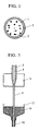
- Fig. 1 is a schematic cross-sectional diagram illustrative of a superconducting wire according to the present invention.
- Reference numeral 1 denotes an oxide superconductor.
- Reference numeral 2 denotes silver or a silver alloy, which has been scattered in the oxide superconductor, and/or a material added for pinning; they are shown in a larger size than they really are. The silver or the silver alloy need not be scattered evenly inside the superconductor; it may be segregated in the vicinity of the surface of the oxide superconductor.
- Reference numeral 3 denotes a conductive material.
- the oxide superconductor used for the superconducting wire according to the present invention is generally produced by heat treatment.
- the density of a sintered compact is frequently lower than a theoretical density.
- vacancies are generated in the superconducting wire.
- the vacancies lead to a lower critical current of the superconducting wire.
- silver or a silver alloy is melted and filled in the vacancies and further, the silver or the silver alloy is dispersed in the oxide superconductor for the purpose of pinning by making use of the filling temperature.
- a conductive material is attached as the stabilizing material to the outer periphery of the superconductor.
- the superconducting wire in accordance with the present invention may be manufactured by any method: for example, a silver pipe is filled with oxide superconductor powder and rolled to be formed into a wire. The wire is then heated to a temperature above 960 degrees centigrade which is the melting temperature of silver. This heating causes the silver to fill the gaps among the crystal grains of the oxide superconductor or to be scattered in the oxide superconductor.
- the conductive material is attached to the outer periphery of the oxide superconductor at the same time as or after the melting of the silver, thereby producing the superconducting wire.
- the oxide superconductor is allowed to pass through the melt of a conductive material, or various deposition processes may be used, or an organometal may be applied and subjected to heat treatment.
- a suitable method for attaching the conductive material should be selected depending on the type of materials used.
- the superconducting wire according to the present invention silver or a silver alloy is scattered in the oxide superconductor to improve the critical current density. Further, the melt of the silver or the silver alloy is also present in vacancies and the recessed spots near the surface of the oxide superconductor, thus providing good adhesion to the conductive material attached around the oxide superconductor.
- the superconducting wire according to this embodiment obtained by using the aforesaid materials and by melting and dispersing the silver as described above showed a critical current density of approximately 10,000 A/cm(5K).
- the critical current density which was obtained when the same oxide superconductor was employed but no silver was melted and dispersed, was approximately 2,000 A/cm, which is extremely smaller than that of this embodiment.
- the superconductive characteristics of the superconducting wire in accordance with this embodiment remained unchanged after winding the superconducting wire by a roller having a diameter of 30 cm, whereas the comparison example, which had no silver melted and dispersed, showed a drop in conductivity to 1/100 to 1/1,000 after winding the wire by the same roller. This proves that the superconducting wire in accordance with the present invention provides high mechanical strength and also high critical current density.
- Fig. 3 shows the conceptual diagram of the manufacturing method for the superconducting wire.
- a silver pipe is filled with an oxide superconductor, then it is formed into a silver sheath wire by using a plurality of dies 5 (Fig. 3 shows only one die).
- the superconductor was charged in the silver pipe measuring 8 mm in outside diameter and 6 mm in inside diameter to produce a fine line 4 having an outside diameter of 0.8 mm.
- Reference numeral 6 denotes a copper melt in a crucible, the melt being produced by a heating device which is not shown. The temperature of the copper melt is maintained at 1,100 degrees centigrade.
- the silver sheath wire obtained as stated above is placed in and let pass through the copper melt 6.
- the wire is wound by a roller (not shown) to take the wire, with the copper attached to the surface thereof, out of the crucible.
- a wire 10 which has been taken out of the crucible, is cooled.
- the copper which has a higher melting point and which is on the outer periphery of the oxide superconductor, starts solidifying first, whereas the inside silver solidifies more slowly than the copper. This difference in solidifying speed enables the silver to be scattered into the gaps and crystals of the oxide superconductor.
- the wire 10 is cooled until the solidification of the silver is completed, then the finished superconducting wire is wound using the roller (not shown).
- the critical current of the superconducting wire of the second embodiment thus produced is 104A/cm or more regardless of the composition of the superconductor materials used. No change in the superconductive characteristics was observed even when a roller having a diameter of about 300 mm was used to wind the superconducting wire. The critical current of the silver sheath wire with no silver melted was about 10A/cm. The oxide superconductor broke when the wire was wound using the roller having the 300mm diameter. The superconducting wire in accordance with the present invention showed almost no change in the critical temperature of the superconductor before it was charged in the silver pipe and after it was formed into the superconducting wire.
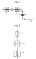
- Fig. 4 shows the conceptual diagram of the manufacturing method for the superconducting wire of the third embodiment.
- a silver pipe with a hole having a diameter of approximately 0.1 to 0.5 mm is filled with materials for producing the superconductor and it is formed into a wire having a diameter of 1 mm by using the die 5.
- the silver pipe is heated by heaters 8 before and after it is drawn by the die so as to produce the oxide superconductor.
- a carbonate or nitrate, or an oxide of a constituent metal element is used as the material for producing the oxide superconductor.
- the hole formed in the silver pipe makes it possible to supply oxygen to the central part of the silver pipe and also to discharge a gas such as carbon dioxide which is generated when the materials are decomposed.
- a superconductor with good characteristics can be produced by the heat treatment using the heaters 8.
- the wire 4 thus obtained is placed in a crucible to let it go through melted gold 6.
- the temperature of the gold melt 6 is maintained at 1,065 to 1,080 degrees centigrade. Since the melting point of silver is 960 degrees centigrade, the silver melts and disperses in the oxide superconductor when the wire 4 is passed through the gold melt 6.
- the wire When the wire is pulled out of the crucible, it has the gold on the surface thereof.
- the gold and silver are partially mixed before they solidify; the mixing ratio can be controlled by the time during which the wire is in contact with the gold melt 6 and the winding speed. There should be no problem as long as the mixing ratio stays constant to a certain level throughout the wire which has been wound.
- the superconducting wire of the third embodiment thus produced exhibits high resistance to mechanical deformation; it can be produced in a length of about 1,000 m even when the roller 7 has a diameter of 200 mm.
- Fig. 5 shows the conceptual diagram of the manufacturing method for the superconducting wire according to the fourth embodiment.
- a pipe made of an alloy of silver with 3wt% of palladium added is filled with an oxide superconductor and formed into a desired sheath wire by using the die 5.
- the sheath wire is then heated by the heating device 11 so as to melt the silver alloy.
- the conductive material is formed on the surface of the sheath wire by using a thin film forming device 9 to make the superconducting wire of this embodiment.
- Any heating device may be used for the heating device 11 as long as it is capable of heating the sheath wire to a temperature at which the silver alloy is melted; infrared rays were concentrated for heating in this embodiment.
- any device may be used for the thin film forming device 9 as long as it is capable of forming a conductive material of the desired thickness; organopalladium was applied and subjected to heat treatment to produce a palladium film in this embodiment.
- the superconducting wire according to this embodiment thus produced exhibits extremely good adhesion between the silver and palladium, minimizing the chance of cracking or the like when the wire is subjected to mechanical deformation. Further, the silver and palladium dispersed in the superconductor have caused the critical current density to increase to a value which is two orders of magnitude or more larger than that of the superconducting wire with no dispersed silver alloy.
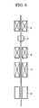
- Fig. 6 is the conceptual diagram illustrative of the manufacturing method for the superconducting wire according to the fifth embodiment.
- a mixture material i.e. the composite material
- the oxide superconductor was charged in a silver alloy pipe which is composed of silver with 1 wt% of magnesium added and which is provided with a plurality of small holes.
- the silver alloy pipe was heated by the heater 8 to remove the gases including the cracked gas, moisture, etc. discharged from the material, thus producing the superconductor of the fifth embodiment.
- the silver alloy pipe filled with the produced oxide superconductor was drawn to a desired size by the die 5 before it was cooled to room temperature.
- the temperature was decreased from 500 to 100 degrees centigrade as the wire diameter decreased, then heat treatment was carried out again by the heater 8.
- the atmosphere for the heat treatment before and after the wire drawing by the dies 5 is selected according to the type of the superconductor employed.
- the conditions for the heat treatment are set so that the oxide superconductor is furnished with the best possible superconductive characteristics by the heat treatment carried out before and after the wire drawing carried out by the dies 5.
- the heat treatment was performed at 930 degrees centigrade.
- the wire formed by the drawing was heated by the heating device 11 to melt the silver alloy on the surface.
- an electric furnace having a kanthal super wire as the heating element was used as the heating device 11.
- the oxide superconductor was cooled and the conductive material was formed on the surface thereof by the thin film forming device 9.
- the conductive material was attached by passing the wire through an aluminum melt in a crucible.
- the superconducting wire according to the fifth embodiment thus produced provided high resistance to mechanical deformation and had a critical current density which is two orders of magnitude larger than that of the superconducting wire with no silver alloy melted and dispersed.
- Fig. 2 shows the flow of the manufacturing method in accordance with the present invention.
- a silver or silver alloy flat tape is prepared and bent so that the cross-sectional area thereof is U-shaped.
- Oxide superconductor powder or a material mixture for the oxide superconductor powder is supplied to the inner side of the U-shaped tape, then it is formed so that the cross-sectional area is O-shaped.
- the both ends of the silver or silver alloy tape may be in contact or overlapped or they may even have a gap, provided the powder inside does not fall.
- the tape is subjected to wire drawing by appropriate figuring. Heat treatment is performed before and after or during the wire drawing as necessary.
- the wire is then led into the crucible to melt the silver or silver alloy thereby to disperse the silver or silver alloy in the superconductor, and the conductive material, which serves as the stabilizer, is attached to the surface of the superconductor.
- the melting of the silver or silver alloy and the attaching of the conductive material may be done at the same time or in succession; they were conducted at the same time in the sixth embodiment.
- Fig. 3 shows the principle for melting the silver or silver alloy and attaching the conductive material at the same time.
- Reference numeral 1 denotes the oxide superconductor powder charged in the silver or silver alloy tape 3 which has been formed to have the O-shaped cross section.
- Reference numeral 5 indicates the die. The drawing shows only one cycle of process; however, a plurality of dies may be used as necessary to implement a plurality of regressive process cycles.
- Reference numeral 4 indicates the material wire which has been formed into a desired shape by the method stated above; the wire is led into the crucible 12 to let it pass through the melt 6 of the conductive material. This causes the silver or silver alloy on the surface of the superconductor to melt. The majority of the melted silver or silver alloy moves into the vacancies or the like in the superconductor although a part thereof is mixed with the melt 6.
- the conductive material is applied to the surface of the wire.
- the conductive material solidifies first, and then the silver or the silver alloy dispersed in the superconductor solidifies.
- the silver or the silver alloy dispersed and solidified in the oxide superconductor enables a higher critical current density.
- the vacancies in the oxide superconductor and the recessed spots near the surface thereof are also filled primarily with the melt of the silver or the silver alloy, thus ensuring good adhesion of the conductive material attached to the outer periphery of the oxide superconductor. All steps including the step for making the silver or silver alloy tape into a pipe and the step for supplying the superconductor powder can be implemented in succession by using a supplying reel and a winding reel (not illustrated in Fig. 3).
- Y2O3, SrCO3, WO3, and CuO were mixed so as to produce 10wt% of SrY2O4 with respect to YSr2Cu 2.8 W 0.2 O Y , then the mixture was subjected to heat treatment at 950 to 1400 degrees centigrade to produce the oxide superconductor.
- the conductive material wrapping around the oxide superconductor Cu was used.
- the same combination of the materials was employed for other embodiments as well as the sixth embodiment to produce the superconducting wire.
- the superconducting wire of this embodiment obtained by using the aforesaid materials and by melting and dispersing the silver as described above exhibited a critical current density of approximately 10,000 A/cm(5K). In contrast to this, the critical current density, which was obtained when the same oxide superconductor was employed but no silver was melted and dispersed, was approximately 2,000 A/cm, which is extremely smaller than that of this embodiment.
- the superconductive characteristics of the superconducting wire in accordance with this embodiment remained unchanged after winding the superconducting wire by the roller having the 30cm diameter, whereas the comparison example, which had no silver melted and dispersed, showed a drop in conductivity to 1/100 to 1/1,000 after winding the wire by the same roller. This proves that the superconducting wire in accordance with the present invention provides high mechanical strength and also high critical current density.
- Fig. 3 shows the conceptual diagram illustrative of the process for melting the silver and attaching the conductive material in the seventh embodiment.
- a silver sheath material which has an oxide superconductor therein and which has been formed into a pipe is processed into a fine line by a plurality of dies 5 (only one die is shown in Fig. 3).
- the silver sheath material measuring 8 mm in outside diameter and 6 mm in inside diameter was formed into the fine line 4 having an outside diameter of 0.8 mm.
- Reference numeral 6 denotes a copper melt in the crucible 12 produced by melting copper by a heating device which is not shown; the temperature of the melt is maintained at 1,090 degrees centigrade.
- the silver sheath material obtained as stated above is placed in the copper melt 6 and let pass through the copper melt 6. At this time, the majority of the silver is melted and dispersed in the oxide superconductor although a part of the silver mixes with the copper melt 6 since the melting point of the silver is 960 degrees centigrade. Then, the wire is wound by a roller, not shown, to take the wire, which has the copper attached to the surface thereof, out of the crucible 12. The wire 10 taken out of the crucible 12 starts solidifying from the outer periphery; it is cooled until the solidification of the silver inside is completed before the finished superconducting wire is wound using the roller which is not shown. Oxygen may be blown into the melted silver so that the oxide superconductor with oxygen reduced may restore the superconductive characteristics. Heat treatment may be performed again after the silver on the outer periphery solidifies.
- the critical current of the superconducting wire thus produced was 104A/cm or more regardless of the composition of the superconductor material used and no change in the superconductive characteristics was observed even when the diameter of the roller winding the superconducting wire was about 300 mm.
- a wire which has the same performance was obtained when a silver tape with a hole having a diameter of 0.5 mm or less was employed to make the superconducting wire in the same manner as stated above.
- the critical current of the resulting wire was about 10A/cm and the observation of the cross section of the obtained wire revealed the presence of a gap over the whole surface between the silver and the superconductor. Such a gap was not observed in the superconducting wire according to the present invention.
- Fig. 4 is the conceptual diagram showing the manufacturing method for the superconducting wire of the eight embodiment.
- a silver tape with a hole of a diameter of about 0.1 mm to about 0.5 mm is formed into a U-shape by continuous rolling.
- the materials for producing the superconductor are supplied to the recessed section of the tape, then the tape is shaped into a pipe by further rolling.
- the wire material is formed into a wire having a diameter of 1 mm by the die 5.
- the silver pipe is heated before and after the die to make the oxide superconductor.
- a carbonate or nitrate, or an oxide of a constituent metal element is used as the material for making the oxide superconductor.
- the hole formed in the silver pipe makes it possible to supply oxygen to the central part of the silver pipe and also to discharge a gas such as carbon dioxide which is generated when the materials are decomposed.
- a superconductor with good characteristics can be produced by the heat treatment using the heaters 8.
- the wire 4 thus obtained is placed in the crucible 12 to let it go through the melted gold 6.
- the temperature of the gold melt 6 is maintained at 1,065 to 1,080 degrees centigrade. Since the melting point of silver is 960 degrees centigrade, the silver melts and disperses in the oxide superconductor when the wire 4 is passed through the gold melt 6.
- the wire is pulled out of the crucible 12, it has the gold on the surface thereof.
- the gold and silver are partially mixed before they solidify; the mixing ratio can be controlled by the time during which the wire is in contact with the gold melt 6 and the winding speed.
- the superconducting wire thus produced exhibits high resistance to mechanical deformation; it can be produced in a length of about 1,000 m even when the diameter of the roller 7 is 200 mm.
- Fig. 5 is the conceptual diagram illustrative of the manufacturing method for the superconducting wire of the ninth embodiment.
- a tape made of an alloy of silver with 3wt% of palladium added is made into a pipe and an oxide superconductor is charged therein, then the pipe is formed into a desired sheath wire by using the die 5.
- the sheath wire is then heated by the heating device 11 so as to melt the silver alloy.
- the conductive material is formed on the surface of the sheath wire by using the thin film forming device 9 to make the superconducting wire.
- any heating device may be used for the heating device 11 as long as it is capable of heating the sheath wire to a temperature at which the silver alloy is melted; infrared rays were concentrated for the heat treatment in this embodiment.
- any device may be used for the thin film forming device 9 as long as it is capable of forming a conductive material of the desired thickness; organopalladium was applied and subjected to heat treatment to produce a palladium film in the ninth embodiment.
- the superconducting wire according to this embodiment thus produced exhibits extremely good adhesion between the silver and palladium, minimizing the chance of cracking or the like when the wire is subjected to mechanical deformation. Further, the silver and palladium dispersed in the superconductor caused the critical current density to increase to a value which is two orders of magnitude or more larger than the critical current density of the superconducting wire with no dispersed silver alloy.
- Fig. 6 is the conceptual diagram showing a part of the manufacturing method for the superconducting wire according to the tenth embodiment.
- the oxide superconductor was charged in a silver alloy tape, which is composed of silver with 1 wt% of magnesium added and which is provided with a plurality of small holes, while shaping the tape into a pipe.
- the silver alloy pipe was heated by the heater 8 to remove the gases including the cracked gas, moisture, etc. discharged from the material, thus producing the superconductor.
- the silver alloy pipe filled with the produced oxide superconductor was drawn to a desired size by the die 5 before it was cooled to room temperature.
- the wire drawing was carried out at 500 to 100 degrees centigrade, then heat treatment was implemented again by the heater 8.
- the atmosphere for the heat treatment before and after the wire drawing by the die 5 is selected according to the type of the superconductor employed.
- the wire formed by the drawing was heated by the heating device 11 to melt the silver alloy on the surface.
- the electric furnace employing the kanthal super wire as the heating element was used as the heating device 11.
- the oxide superconductor was cooled and the conductive material was formed on the surface thereof by the thin film forming device 9.
- the conductive material was attached by passing the wire through the aluminum melt in the crucible. The heat treatment prior to the wire drawing step may be omitted if the oxide superconductor powder is supplied to the silver alloy tape.
- the superconducting wire thus produced provided high resistance to mechanical deformation and had a critical current density which is two orders of magnitude larger than that of the superconducting wire with no silver alloy melted and dispersed.
- a highly reliable, practical superconducting wire which is capable of fully displaying the characteristics of an oxide superconductor employed for the superconducting wire without incurring a drop in the critical temperature or the critical current during the manufacturing process and which also provides high resistance to mechanical deformation.
Landscapes
- Engineering & Computer Science (AREA)
- Chemical & Material Sciences (AREA)
- Manufacturing & Machinery (AREA)
- Ceramic Engineering (AREA)
- Materials Engineering (AREA)
- Structural Engineering (AREA)
- Organic Chemistry (AREA)
- Superconductors And Manufacturing Methods Therefor (AREA)
- Inorganic Compounds Of Heavy Metals (AREA)
Applications Claiming Priority (6)
| Application Number | Priority Date | Filing Date | Title |
|---|---|---|---|
| JP259626/94 | 1994-09-30 | ||
| JP6259626A JP3071110B2 (ja) | 1994-09-30 | 1994-09-30 | 超伝導線の製造方法 |
| JP25962394 | 1994-09-30 | ||
| JP25962694 | 1994-09-30 | ||
| JP259623/94 | 1994-09-30 | ||
| JP06259623A JP3123699B2 (ja) | 1994-09-30 | 1994-09-30 | 超伝導線の製造方法 |
Publications (3)
| Publication Number | Publication Date |
|---|---|
| EP0704862A2 true EP0704862A2 (de) | 1996-04-03 |
| EP0704862A3 EP0704862A3 (de) | 1996-07-24 |
| EP0704862B1 EP0704862B1 (de) | 2003-01-22 |
Family
ID=26544213
Family Applications (1)
| Application Number | Title | Priority Date | Filing Date |
|---|---|---|---|
| EP95306444A Expired - Lifetime EP0704862B1 (de) | 1994-09-30 | 1995-09-14 | Verfahren zur Herstellung eines supraleitenden Drahts |
Country Status (3)
| Country | Link |
|---|---|
| US (2) | US20020023772A1 (de) |
| EP (1) | EP0704862B1 (de) |
| DE (1) | DE69529443T2 (de) |
Cited By (1)
| Publication number | Priority date | Publication date | Assignee | Title |
|---|---|---|---|---|
| EP0742595B1 (de) * | 1995-05-11 | 2001-11-14 | Canon Kabushiki Kaisha | Verfahren zur Herstellung eines metallimprägnierten Supraleiters |
Families Citing this family (3)
| Publication number | Priority date | Publication date | Assignee | Title |
|---|---|---|---|---|
| US6610930B1 (en) * | 1998-09-16 | 2003-08-26 | Kulicke & Soffa Investments, Inc. | Composite noble metal wire |
| US7608785B2 (en) * | 2004-04-27 | 2009-10-27 | Superpower, Inc. | System for transmitting current including magnetically decoupled superconducting conductors |
| WO2016063255A1 (en) * | 2014-10-23 | 2016-04-28 | Brightsource Industries (Israel) Ltd. | High-temperature solar-absorptive coatings with high thermal conductivity and low emissivity, and methods for use thereof |
Citations (3)
| Publication number | Priority date | Publication date | Assignee | Title |
|---|---|---|---|---|
| JPS63241826A (ja) | 1987-03-30 | 1988-10-07 | Fujikura Ltd | 超電導線の製造方法 |
| JPH01276516A (ja) | 1988-04-28 | 1989-11-07 | Mitsubishi Metal Corp | 高臨界電流密度を有する超電導線材の製造法 |
| JPH0237623A (ja) | 1988-07-28 | 1990-02-07 | Sumitomo Heavy Ind Ltd | 酸化物超電導線材の作製方法 |
Family Cites Families (35)
| Publication number | Priority date | Publication date | Assignee | Title |
|---|---|---|---|---|
| CA1338396C (en) | 1987-02-05 | 1996-06-18 | Kazuo Sawada | Process for manufacturing a superconducting wire of compound oxide-type ceramics |
| EP0281474B2 (de) | 1987-02-28 | 2006-05-24 | Sumitomo Electric Industries Limited | Verfahren zur Herstellung eines Oxid-Verbindungssupraleiterfadens |
| EP0505015B1 (de) | 1987-03-13 | 1997-05-14 | Kabushiki Kaisha Toshiba | Supraleitender Draht und Verfahren zu seiner Herstellung |
| US5204318A (en) | 1987-03-27 | 1993-04-20 | Massachusetts Institute Of Technology | Preparation of superconducting oxides and oxide-metal composites |
| US5552370A (en) | 1987-03-30 | 1996-09-03 | Hewlett-Packard Company | Silver additives for ceramic superconductors |
| US5202307A (en) | 1987-03-30 | 1993-04-13 | Sumitomo Electric Industries, Ltd. | Method of manufacturing superconducting wire |
| US5071826A (en) | 1987-03-30 | 1991-12-10 | Hewlett-Packard Company | Organometallic silver additives for ceramic superconductors |
| DE3853965T2 (de) | 1987-03-31 | 1996-02-22 | Sumitomo Electric Industries | Supraleitender Verbundwerkstoff. |
| CA1324190C (en) | 1987-05-01 | 1993-11-09 | Susumu Yamamoto | Process for manufacturing a superconducting composite |
| US5081075A (en) | 1987-05-12 | 1992-01-14 | At&T Laboratories | Method of producing a superconductive body, and apparatus and systems comprising the body |
| DE3716815C2 (de) * | 1987-05-20 | 1997-07-31 | Kabelmetal Electro Gmbh | Verfahren zur kontinuierlichen Herstellung eines Supraleiters |
| JPH01251514A (ja) | 1987-05-25 | 1989-10-06 | Hitachi Ltd | 超電導線及びその製造方法 |
| US5106825A (en) | 1987-07-31 | 1992-04-21 | Olin Corporation | Fabrication of superconducting wire and product |
| US5063200A (en) | 1987-08-12 | 1991-11-05 | Hitachi, Ltd. | Ceramic superconductor article |
| JPS6457535A (en) | 1987-08-27 | 1989-03-03 | Mitsubishi Metal Corp | Manufacture of superconductive ceramics wire |
| JPH01161612A (ja) | 1987-12-18 | 1989-06-26 | Furukawa Electric Co Ltd:The | 酸化物系超電導線材 |
| JPH01176608A (ja) | 1987-12-29 | 1989-07-13 | Furukawa Electric Co Ltd:The | 酸化物超電導線条体の製造方法 |
| JPH0676266B2 (ja) | 1988-07-13 | 1994-09-28 | 日本碍子株式会社 | 酸化物超電導焼結体およびその製造方法 |
| JPH02230612A (ja) * | 1989-03-02 | 1990-09-13 | Sumitomo Electric Ind Ltd | 酸化物超電導線材の製造方法 |
| JP2835083B2 (ja) | 1989-07-03 | 1998-12-14 | 古河電気工業株式会社 | 酸化物超電導体の製造方法 |
| US5082826A (en) | 1989-08-02 | 1992-01-21 | The United States Of America As Represented By The Secretary Of The Navy | Silver coated superconducting ceramic powder |
| JP3179084B2 (ja) * | 1990-01-20 | 2001-06-25 | 同和鉱業株式会社 | 酸化物超電導線材の製造方法 |
| JPH04181613A (ja) | 1990-11-14 | 1992-06-29 | Furukawa Electric Co Ltd:The | テープ状酸化物超電導導体の製造方法 |
| JPH04262310A (ja) * | 1991-01-21 | 1992-09-17 | Mitsubishi Electric Corp | 酸化物超電導線材の製造方法 |
| JPH04272616A (ja) * | 1991-02-27 | 1992-09-29 | Aisin Seiki Co Ltd | 超電導線材及びその製造方法 |
| JPH04281444A (ja) | 1991-03-11 | 1992-10-07 | Mitsubishi Rayon Co Ltd | 両面レンチキュラーレンズシート、ならびにその製造方法及び製造装置 |
| DE69219817T2 (de) | 1991-03-22 | 1997-10-16 | Canon Kk | Metalloxidisches Material |
| JP3181642B2 (ja) * | 1991-10-09 | 2001-07-03 | 同和鉱業株式会社 | 酸化物超電導線材の製造方法 |
| JPH05166426A (ja) | 1991-12-13 | 1993-07-02 | Furukawa Electric Co Ltd:The | セラミックス超電導々体の製造方法 |
| JP2501281B2 (ja) * | 1992-02-12 | 1996-05-29 | インターナショナル・ビジネス・マシーンズ・コーポレイション | 高臨界電流密度の超伝導体を製造する方法 |
| WO1993017969A1 (en) | 1992-03-02 | 1993-09-16 | The University Of Kansas | Superconductors having continuous ceramic and elemental metal matrices |
| JP3217905B2 (ja) | 1992-06-26 | 2001-10-15 | キヤノン株式会社 | 金属酸化物材料及びその製造方法 |
| US5418214A (en) | 1992-07-17 | 1995-05-23 | Northwestern University | Cuprate-titanate superconductor and method for making |
| DE69312199T2 (de) | 1992-09-29 | 1997-10-30 | Canon Kk | Verfahren zur Herstellung von Metall-Oxid und so erhaltenes Metal-Oxid |
| JP3219563B2 (ja) | 1993-09-02 | 2001-10-15 | キヤノン株式会社 | 金属酸化物とその製造方法 |
-
1995
- 1995-09-14 DE DE69529443T patent/DE69529443T2/de not_active Expired - Fee Related
- 1995-09-14 US US08/528,538 patent/US20020023772A1/en not_active Abandoned
- 1995-09-14 EP EP95306444A patent/EP0704862B1/de not_active Expired - Lifetime
-
2000
- 2000-09-29 US US09/672,315 patent/US6604273B1/en not_active Expired - Fee Related
Patent Citations (3)
| Publication number | Priority date | Publication date | Assignee | Title |
|---|---|---|---|---|
| JPS63241826A (ja) | 1987-03-30 | 1988-10-07 | Fujikura Ltd | 超電導線の製造方法 |
| JPH01276516A (ja) | 1988-04-28 | 1989-11-07 | Mitsubishi Metal Corp | 高臨界電流密度を有する超電導線材の製造法 |
| JPH0237623A (ja) | 1988-07-28 | 1990-02-07 | Sumitomo Heavy Ind Ltd | 酸化物超電導線材の作製方法 |
Cited By (2)
| Publication number | Priority date | Publication date | Assignee | Title |
|---|---|---|---|---|
| EP0742595B1 (de) * | 1995-05-11 | 2001-11-14 | Canon Kabushiki Kaisha | Verfahren zur Herstellung eines metallimprägnierten Supraleiters |
| US6381832B1 (en) | 1995-05-11 | 2002-05-07 | Canon Kabushiki Kaisha | Process for the production of a superconducting wire having a stacked structure |
Also Published As
| Publication number | Publication date |
|---|---|
| DE69529443T2 (de) | 2003-10-02 |
| DE69529443D1 (de) | 2003-02-27 |
| US20020023772A1 (en) | 2002-02-28 |
| EP0704862B1 (de) | 2003-01-22 |
| EP0704862A3 (de) | 1996-07-24 |
| US6604273B1 (en) | 2003-08-12 |
Similar Documents
| Publication | Publication Date | Title |
|---|---|---|
| JP2711358B2 (ja) | 超電導線材の製造方法 | |
| US5981444A (en) | Process for manufacturing a superconducting wire of compound oxide-type ceramics | |
| EP0282286B2 (de) | Supraleitender Draht und Verfahren zu seiner Herstellung | |
| US5283232A (en) | Method for producing oxide superconducting composite wire | |
| EP0292385B1 (de) | Verfahren zur Herstellung oxidkeramischer supraleitender Fäden | |
| JP3521182B2 (ja) | 酸化物超電導線材及び超電導装置 | |
| US6604273B1 (en) | Method of manufacturing an oxide superconducting wire | |
| EP0742595B1 (de) | Verfahren zur Herstellung eines metallimprägnierten Supraleiters | |
| JP3123699B2 (ja) | 超伝導線の製造方法 | |
| KR910009198B1 (ko) | 초전도 성형체의 제조방법 | |
| JP3071110B2 (ja) | 超伝導線の製造方法 | |
| JP3466758B2 (ja) | ほう素を含有する金属酸化物線材、及び金属酸化物線材の製造方法 | |
| US5346883A (en) | Method of manufacturing superconductive products | |
| JPH04124032A (ja) | 超電導体及びその合成法 | |
| JPH01164799A (ja) | 超電導成形体の製造方法 | |
| JPH03163714A (ja) | 酸化物超電導導体の製造方法 | |
| JPS63266715A (ja) | 超電導線の製造方法 | |
| JPH03110714A (ja) | セラミックス超電導々体 | |
| JPH03110715A (ja) | セラミックス超電導々体 | |
| JPH0195413A (ja) | 酸化物超電導線の製造方法 | |
| JPS63291320A (ja) | 酸化物系超電導線の製造方法 | |
| JPH07130230A (ja) | 酸化物超電導線及びその製造方法 |
Legal Events
| Date | Code | Title | Description |
|---|---|---|---|
| PUAI | Public reference made under article 153(3) epc to a published international application that has entered the european phase |
Free format text: ORIGINAL CODE: 0009012 |
|
| AK | Designated contracting states |
Kind code of ref document: A2 Designated state(s): DE FR GB |
|
| PUAL | Search report despatched |
Free format text: ORIGINAL CODE: 0009013 |
|
| AK | Designated contracting states |
Kind code of ref document: A3 Designated state(s): DE FR GB |
|
| 17P | Request for examination filed |
Effective date: 19961204 |
|
| 17Q | First examination report despatched |
Effective date: 19971203 |
|
| GRAG | Despatch of communication of intention to grant |
Free format text: ORIGINAL CODE: EPIDOS AGRA |
|
| RTI1 | Title (correction) |
Free format text: METHOD OF MANUFACTURING A SUPERCONDUCTING WIRE |
|
| RTI1 | Title (correction) |
Free format text: METHOD OF MANUFACTURING A SUPERCONDUCTING WIRE |
|
| GRAG | Despatch of communication of intention to grant |
Free format text: ORIGINAL CODE: EPIDOS AGRA |
|
| GRAG | Despatch of communication of intention to grant |
Free format text: ORIGINAL CODE: EPIDOS AGRA |
|
| GRAH | Despatch of communication of intention to grant a patent |
Free format text: ORIGINAL CODE: EPIDOS IGRA |
|
| RIN1 | Information on inventor provided before grant (corrected) |
Inventor name: KANEKO, NORIO |
|
| GRAH | Despatch of communication of intention to grant a patent |
Free format text: ORIGINAL CODE: EPIDOS IGRA |
|
| GRAA | (expected) grant |
Free format text: ORIGINAL CODE: 0009210 |
|
| AK | Designated contracting states |
Kind code of ref document: B1 Designated state(s): DE FR GB |
|
| REG | Reference to a national code |
Ref country code: GB Ref legal event code: FG4D |
|
| REF | Corresponds to: |
Ref document number: 69529443 Country of ref document: DE Date of ref document: 20030227 Kind code of ref document: P |
|
| ET | Fr: translation filed | ||
| PLBE | No opposition filed within time limit |
Free format text: ORIGINAL CODE: 0009261 |
|
| STAA | Information on the status of an ep patent application or granted ep patent |
Free format text: STATUS: NO OPPOSITION FILED WITHIN TIME LIMIT |
|
| 26N | No opposition filed |
Effective date: 20031023 |
|
| PGFP | Annual fee paid to national office [announced via postgrant information from national office to epo] |
Ref country code: FR Payment date: 20040927 Year of fee payment: 10 |
|
| PGFP | Annual fee paid to national office [announced via postgrant information from national office to epo] |
Ref country code: DE Payment date: 20041124 Year of fee payment: 10 |
|
| PGFP | Annual fee paid to national office [announced via postgrant information from national office to epo] |
Ref country code: GB Payment date: 20050831 Year of fee payment: 11 |
|
| PG25 | Lapsed in a contracting state [announced via postgrant information from national office to epo] |
Ref country code: DE Free format text: LAPSE BECAUSE OF NON-PAYMENT OF DUE FEES Effective date: 20060401 |
|
| PG25 | Lapsed in a contracting state [announced via postgrant information from national office to epo] |
Ref country code: FR Free format text: LAPSE BECAUSE OF NON-PAYMENT OF DUE FEES Effective date: 20060531 |
|
| REG | Reference to a national code |
Ref country code: FR Ref legal event code: ST Effective date: 20060531 |
|
| GBPC | Gb: european patent ceased through non-payment of renewal fee |
Effective date: 20060914 |
|
| PG25 | Lapsed in a contracting state [announced via postgrant information from national office to epo] |
Ref country code: GB Free format text: LAPSE BECAUSE OF NON-PAYMENT OF DUE FEES Effective date: 20060914 |