EP0704950A1 - Isolator für einen durchgehenden Leiter - Google Patents
Isolator für einen durchgehenden Leiter Download PDFInfo
- Publication number
- EP0704950A1 EP0704950A1 EP95810581A EP95810581A EP0704950A1 EP 0704950 A1 EP0704950 A1 EP 0704950A1 EP 95810581 A EP95810581 A EP 95810581A EP 95810581 A EP95810581 A EP 95810581A EP 0704950 A1 EP0704950 A1 EP 0704950A1
- Authority
- EP
- European Patent Office
- Prior art keywords
- insulator
- continuous conductor
- conductor
- sleeve
- wall
- Prior art date
- Legal status (The legal status is an assumption and is not a legal conclusion. Google has not performed a legal analysis and makes no representation as to the accuracy of the status listed.)
- Granted
Links
- 239000004020 conductor Substances 0.000 title claims abstract description 53
- 239000012212 insulator Substances 0.000 title claims description 51
- 239000013013 elastic material Substances 0.000 claims abstract description 7
- 230000008719 thickening Effects 0.000 claims description 7
- 230000036316 preload Effects 0.000 claims 1
- 230000002093 peripheral effect Effects 0.000 abstract 1
- 230000005520 electrodynamics Effects 0.000 description 4
- RYGMFSIKBFXOCR-UHFFFAOYSA-N Copper Chemical compound [Cu] RYGMFSIKBFXOCR-UHFFFAOYSA-N 0.000 description 3
- 229910052802 copper Inorganic materials 0.000 description 3
- 239000010949 copper Substances 0.000 description 3
- 238000004519 manufacturing process Methods 0.000 description 3
- 238000000034 method Methods 0.000 description 3
- 125000006850 spacer group Chemical group 0.000 description 3
- 238000005266 casting Methods 0.000 description 2
- 239000003822 epoxy resin Substances 0.000 description 2
- 239000007789 gas Substances 0.000 description 2
- 239000011261 inert gas Substances 0.000 description 2
- 229920000647 polyepoxide Polymers 0.000 description 2
- 238000007789 sealing Methods 0.000 description 2
- 230000009286 beneficial effect Effects 0.000 description 1
- 229920001971 elastomer Polymers 0.000 description 1
- 238000009434 installation Methods 0.000 description 1
- 239000000314 lubricant Substances 0.000 description 1
- 239000000463 material Substances 0.000 description 1
- 239000002184 metal Substances 0.000 description 1
- 229910052751 metal Inorganic materials 0.000 description 1
- 239000004033 plastic Substances 0.000 description 1
- 229920003023 plastic Polymers 0.000 description 1
- 229920002635 polyurethane Polymers 0.000 description 1
- 239000004814 polyurethane Substances 0.000 description 1
- 230000001681 protective effect Effects 0.000 description 1
Images


Classifications
-
- H—ELECTRICITY
- H01—ELECTRIC ELEMENTS
- H01B—CABLES; CONDUCTORS; INSULATORS; SELECTION OF MATERIALS FOR THEIR CONDUCTIVE, INSULATING OR DIELECTRIC PROPERTIES
- H01B17/00—Insulators or insulating bodies characterised by their form
- H01B17/26—Lead-in insulators; Lead-through insulators
- H01B17/30—Sealing
- H01B17/303—Sealing of leads to lead-through insulators
- H01B17/308—Sealing of leads to lead-through insulators by compressing packing material
-
- H—ELECTRICITY
- H02—GENERATION; CONVERSION OR DISTRIBUTION OF ELECTRIC POWER
- H02B—BOARDS, SUBSTATIONS OR SWITCHING ARRANGEMENTS FOR THE SUPPLY OR DISTRIBUTION OF ELECTRIC POWER
- H02B13/00—Arrangement of switchgear in which switches are enclosed in, or structurally associated with, a casing, e.g. cubicle
- H02B13/005—Electrical connection between switchgear cells
-
- H—ELECTRICITY
- H02—GENERATION; CONVERSION OR DISTRIBUTION OF ELECTRIC POWER
- H02B—BOARDS, SUBSTATIONS OR SWITCHING ARRANGEMENTS FOR THE SUPPLY OR DISTRIBUTION OF ELECTRIC POWER
- H02B13/00—Arrangement of switchgear in which switches are enclosed in, or structurally associated with, a casing, e.g. cubicle
- H02B13/02—Arrangement of switchgear in which switches are enclosed in, or structurally associated with, a casing, e.g. cubicle with metal casing
- H02B13/035—Gas-insulated switchgear
- H02B13/045—Details of casing, e.g. gas tightness
Definitions
- the above invention relates to an insulator for a continuous conductor.
- control cabinets which consist of several chambers and which are advantageously made of sheet metal and are usually filled with an inert gas, such as SF6, a current via electrical conductors from one chamber of the control cabinet into an adjacent chamber of the control cabinet flows.
- an inert gas such as SF6
- insulators in the wall parts of two adjacent chambers of the control cabinet, which are usually cup-shaped or bell-shaped.
- insulators are mounted and fastened in a desired position with the aid of spacer rings which are arranged between the wall parts of the chambers of the control cabinet. Threaded nuts are also used to hold the body of the insulator in its working position.
- a through hole is made in the bottom of the insulator, which is cup-shaped or bell-shaped, in which a continuous conductor is permanently installed according to the state of the art.
- the continuous conductor consists of a cylindrical, rod-shaped body, the ends of which protrude into the adjacent chambers of the electrical control cabinet, where the ends of the conductor are connected to electrically conductive cables.
- the mechanical connection between the body of the insulator and the body of the continuous conductor which is produced using the known manufacturing methods, represents a firm and rigid connection which does not allow the position of the copper conductor to be adjusted after the device has been installed. It has also been found that mechanical or electrodynamic loads on the Act on the body of the insulator, can damage the rigid connection between the insulator and the continuous conductor, which leads to leakage and the escape of the inert gas. The electrodynamic loads that are transmitted to the body of the insulator can lead to unwanted vibrations inside the control cabinet.
- the object of the above invention is to avoid the disadvantages of the prior art and to provide a new insulator for a continuous conductor, which can be assembled via an automatic manufacturing process, a completely sealed assembly between the insulator body and the continuous conductor being possible, and that it is also possible to elastically support the continuous conductor in the body of the insulator.
- annular thickening protrudes from the wall which delimits the bore in the body of the insulator and is oriented radially to the center of the bore.
- the cylindrical body of the continuous conductor has a circumferential groove into which part of the elastically deformable receiving sleeve penetrates.
- the circumferential groove of the continuous conductor is advantageously defined by two frustoconical bodies which are connected to one another via their ends having the smaller diameter.
- the groove base has the shape of a knurled or knurled band.
- the wall which delimits the through hole in the body of the insulator, as a convex wall with a curvature towards the center of the hole.
- the body of the insulator and the continuous conductor are connected to each other using an elastic component; this gives you the opportunity to Automate assembly processes.
- the insulator for the continuous conductor designed according to the invention does not form a rigid body after the components have been joined; this makes it possible to absorb or compensate for axial or transverse movements. Such movements can occur due to mechanical and / or electrodynamic loading, but it is important that the structure of the insulator and thus its tightness are not affected. Furthermore, it is avoided that the vibrations due to electrodynamic loads on the insulator body are undesirably transmitted to the control cabinet.
- the insulator 1 is assembled with the aid of a spacer ring 2 and with the aid of fastening disks 3 and 4 which are fastened between the walls 6 and 7 with the aid of screws 5.
- the walls 6, 7 delimit two chambers 8 and 9 of an electrical control cabinet known per se.
- sealing rings 10 and 11 are arranged, which seal the chambers 8 and 9, which are filled with a protective gas (SF6).
- SF6 protective gas
- the insulator is cup-shaped and a through hole 14 is made in its bottom, which according to the invention receives an elastic sleeve 15 which is penetrated by a cylindrical conductor 16.
- the end 12 of the cylindrical conductor 16 is connected to a tubular clamp 17, whereas the end 13 is connected to a flat clamp 18.
- the conductor 16 has a groove 19 into which the inner piece 20 of the tubular sleeve 15 penetrates. 2 shows further details of the invention.
- a thickening 21 projects from the wall 26, which delimits the through-bore 14, radially to the interior of the bore 14 positive connection with a groove 22 which is incorporated into the outer circumferential surface 27 of the elastic sleeve 15.
- the annular thickening 21 can also be operatively connected to the elastic body 15 of the sleeve by simply deforming the elastic material of the sleeve 15.
- the elastic material of the sleeve 15 advantageously consists of rubber or a polyurethane material or another plastic which has the required elasticity.
- the continuous conductor 16 in accordance with the elastic sleeve 15, receives a circumferential groove, which is identified overall by 19.
- the groove 19 is particularly advantageously delimited by the circumferential surfaces of two bodies 23 and 24 formed like a truncated cone; these are connected with their ends, which have a smaller diameter.
- the elastic sleeve 15 has dimensions such that it is ensured that when the continuous conductor 16 is introduced into the bore 25 of the elastic sleeve 15, this sleeve is elastically deformed and loaded in such a way that a prestressed body is formed which is formed with a certain clamping force on the wall 26 of the through hole 14 and on the walls of the circumferential groove 19.
- the bottom 28 of the groove 19 forms a circumferential band 30, advantageously a knurled or corded band, which leads to increased grip and thus ensures a very secure arrangement of the continuous conductor 16 inside the insulator 1.
- the continuous conductor 16 performs an undesirable rotary movement about its longitudinal axis.
- connection of the insulator 1 with the elastic sleeve 15 and the continuous conductor 16 is described in more detail with reference to FIG. 3.
- the elastic sleeve 15 is inserted under prestress into the through hole 14 of the insulator 1. It follows that, thanks to the selected dimensions, the sleeve 15 made of elastic material is prestressed and non-positively and / or positively blocked in the interior of the through bore 14. Subsequently, the conductor 16, which is advantageously coated with a volatilizing lubricant, is subjected to a force (P), which is applied, for example, with the stamp of an assembly press, in order to be inserted into the bore 25 of the elastic sleeve 15 . As a result, the body of the sleeve 15 is further elastically deformed and further biased. The continuous conductor 16 is advanced so far under the action of the force (P) until the groove 19 completely receives the elastic sleeve 15. Due to the elastic sleeve 15, the empty space, which is delimited by the circumferential groove 19, is completely filled.
- the sleeve 15 and the circumferential groove 19 are dimensioned in such a way that it is ensured that, even after an operative connection between the groove 19 and the body of the sleeve 15, the latter remains sufficiently compressed to ensure that the circumference 19 is fixed by the sleeve 15 with the desired Tension is maintained.
- Fig. 4 can be seen that the insulator 1, thanks to the provision of the elastic sleeve 15, which is arranged with bias, receives the continuous conductor 16 in a precisely defined position. At the same time, however, a slight pivoting 16 ′ of the continuous conductor 16 (dash-dot line) relative to the body of the insulator 1 is made possible. This fact allows a simpler assembly of the insulator 1 together with the continuous conductor 16 inside the electrical control cabinet and it opens up the possibility of certain tolerances in the Compensate dimensions.
- the continuous conductor 16 is elastically mounted in the interior of the insulator 1, which enables vibrations or deformations of the components to be compensated for due to mechanical loads or due to the presence of electro-mechanical forces.
- the wall 26, which delimits the through bore 14 of the insulator 1, is designed as a convexly curved wall which forms a receptacle which surrounds the sleeve 15 in a form-fitting manner.
- the invention can also be implemented by means of a disk-shaped insulator 1, the disk-shaped insulator 1 having a thickening 1 'in the middle and with the interposition of an elastic sleeve 15 receiving the continuous conductor 16, which for this purpose has a Has connecting groove 19.
Landscapes
- Engineering & Computer Science (AREA)
- Power Engineering (AREA)
- Insulating Bodies (AREA)
- Superconductors And Manufacturing Methods Therefor (AREA)
- Processes Specially Adapted For Manufacturing Cables (AREA)
- Insulated Conductors (AREA)
Abstract
Description
- Die vorstehende Erfindung betrifft einen Isolator für einen durchgehenden Leiter.
- Es ist bekannt, daß in Schaltschränken, die aus mehreren Kammern bestehen und welche in vorteilhafter Weise aus Blech hergestellt sind und üblicherweise mit einem Inertgas, wie zum Beispiel SF₆ gefüllt sind, ein Strom über elektrische Leiter von der einen Kammer des Schaltschrankes in eine danebenliegende Kammer des Schaltschrankes fließt. Zu diesem Zweck ist es üblich, in die Wandteile von zwei nebeneinander liegenden Kammern des Schaltschrankes Isolatoren einzubauen, die üblicherweise tassen- oder glockenförmig ausgebildet sind.
- Diese Isolatoren werden in einer gewünschten Lage unter Zuhilfenahme von Abstandsringen, die zwischen den Wandteilen der Kammern des Schaltschrankes angeordnet sind, montiert und befestigt. Ferner finden Gewindemuttern Verwendung, mit denen der Körper des Isolators in seiner Arbeitslage gehalten wird.
- In den Boden des Isolators, der tassen- oder glockenförmig ausgebildet ist, ist eine durchgehende Bohrung eingebracht, in die nach dem Stand der Technik ein durchgehender Leiter fest eingebaut ist. Der durchgehende Leiter besteht in diesem Fall aus einem zylindrischen, stangenförmigen Körper, dessen Enden in die benachbarten Kammern des elektrischen Schaltschrankes ragen, wo die Enden des Leiters mit elektrisch leitenden Kabeln verbunden sind.
- Es konnte festgestellt werden, daß die feste Verbindung zwischen dem Körper des Isolators, der zum Beispiel aus Epoxydharz besteht, und dem aus Kupfer bestehenden Leiter, unter Einsatz eines Gießverfahrens oder eines ähnlichen Vorganges wesentliche Nachteile mit sich bringt.
- Der Einbau des Leiters in den Körper des Isolators ist arbeitsaufwendig, die Lageanordnung des aus Kupfer bestehenden Leiters gegenüber dem Körper des Isolators erfordert einen erheblichen Zeitaufwand für das Vergießen des Epoxydharzes, und die Notwendigkeit einer genauen Lageanordnung des Leiters erlaubt keine Automatisierung des Fertigungsvorganges.
- Die mit den bekannten Fertigungsverfahren hergestellte mechanische Verbindung zwischen dem Körper des Isolators und dem Körper des durchgehenden Leiters stellt eine feste und starre Verbindung dar, die keine Lageanpassung des aus Kupfer bestehenden Leiters nach der Montage der Vorrichtung ermöglicht. Ferner hat es sich herausgestellt, daß mechanische oder elektrodynamische Belastungen, die auf den Körper des Isolators einwirken, zu einer Beschädigung der starren Verbindung zwischen dem Isolator und dem durchgehenden Leiter führen können, was zu einer Leckbildung und zum Austritt des Inertgases führt. Die elektrodynamischen Belastungen, die auf den Körper des Isolators übertragen werden, können zu unerwüschten Schwingungen im Inneren des Schaltschrankes führen.
- Aufgabe der vorstehenden Erfindung ist es, die Nachteile des Standes der Technik zu vermeiden und einen neuen Isolator für einen durchgehenden Leiter zu schaffen, der über einen automatischen Fertigungsvorgang montierbar ist, wobei ein vollständig abgedichtetes Zusammenfügen zwischen Isolatorkörper und durchgehendem Leiter möglich wird, und daß es ferner möglich ist, den durchgehenden Leiter elastisch im Körper des Isolators zu lagern.
- Diese Vorteile werden dadurch erreicht, daß zwischen den Wandungen, welche die durchgehende Bohrung im Körper des Isolators begrenzen und dem Körper des durchgehenden Leiters unter Vorspannung eine Aufnahmehülse aus elastischem Material eingesetzt ist.
- In vorteilhafter Weise steht von der Wandung, die die Bohrung im Körper des Isolators begrenzt, eine ringförmige Verdickung ab, die radial zum Zentrum der Bohrung ausgerichtet ist.
- Es hat sich als vorteilhaft erwiesen, in der äußeren Umfangsfläche der elastischen Aufnahmehülse eine Nut vorzusehen, mit der die ringförmig ausgebildete, radial von der Wandung der Durchgangsbohrung abstehende Verdickung in Verbindung bringbar ist.
- Mit besonderem Vorteil weist der zylinderförmige Körper des durchgehenden Leiters eine Umfangsnut auf, in die ein Teil der elastisch verformbaren Aufnahmehülse eindringt.
- In vorteilhafter Weise wird die Umfangsnut des durchgehenden Leiters von zwei kegelstumpfartigen Körpern definiert, die miteinander über ihre den kleineren Durchmesser aufweisenden Enden verbunden sind.
- Um die mechanische Verbindung zwischen der elastischen Aufnahmehülse und der in den durchgehenden Leiter eingearbeiteten Nut verbessern zu können, weist der Nutgrund die Form eines gekordelten oder gerändelten Bandes auf.
- Es hat sich ferner als vorteilhaft erwiesen, die Wandung, welche die durchgehende Bohrung im Körper des Isolators begrenzt, als konvex ausgebildete Wand mit einer Wölbung zum Zentrum der Bohrung hin auszubilden.
- Mit dem Isolator für einen durchgehenden Leiter gemäß der Erfindung werden folgende Vorteile erzielt:
- Der Körper des Isolators und der durchgehende Leiter werden untereinander durch Verwendung eines elastischen Bauteiles verbunden; dadurch besteht die Möglichkeit, die Montagevorgänge zu automatisieren.
- Der erfindungsgemäss ausgebildete Isolator für den durchgehenden Leiter bildet nach Zusammenfügen der Bauteile keinen starren Körper; dies ermöglicht es, axial oder quer gerichtete Bewegungen aufzunehmen oder auszugleichen. Solche Bewegungen können aufgrund mechanischer und/oder elektrodynamischer Belastung auftreten, es ist aber wichtig, daß dabei die Struktur des Isolators und somit dessen Dichtigkeit nicht beeinflußt wird. Des weiteren wird vermieden, daß die Schwingungen aufgrund von elektrodynamischen Belastungen des Isolatorkörpers in unerwünschter Weise auf den Schaltschrank übertragen werden.
- Weitere Vorteile der Erfindung können der folgenden Beschreibung sowie den beigefügten Zeichnungen entnommen werden:
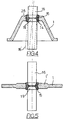
- Fig. 1 zeigt einen Schnitt des gesamten Isolators, der zwischen zwei Wandungen, welche zwei Kammern eines Schaltschrankes begrenzen, angeordnet sind;
- Fig. 2 zeigt im Schnitt ein erstes Ausführungsbeispiel des Isolators;
- Fig. 3 zeigt schematisch den Montagevorgang des Isolators;
- Fig. 4 zeigt schematisch eine erste Ausführungsform des erfindungsgemäßen Isolators; und
- Fig. 5 zeigt eine weitere Ausführungsform eines Isolators gemäß der Erfindung.
- Wie der Fig. 1 zu entnehmen ist, erfolgt die Montage des Isolators 1 unter Zuhilfenahme eines Abstandsringes 2 sowie unter Zuhilfenahme von Befestigungsscheiben 3 und 4, die unter Zuhilfenahme von Schrauben 5 zwischen den Wandungen 6 und 7 befestigt sind. Die Wandungen 6, 7 begrenzen zwei Kammern 8 und 9 eines an sich bekannten elektrischen Schaltschrankes.
- Auf beiden Seiten des Abstandsringes 2 sind Dichtungsringe 10 bzw. 11 angeordnet, welche die Kammern 8 und 9, die mit einem Schutzgas (SF₆) gefüllt sind, abdichten.
- In Fig. 1 ist der Isolator tassenförmig ausgebildet und in seinem Boden ist eine Durchgangsbohrung 14 eingebracht, die erfindungsgemäß eine elastische Hülse 15 aufnimmt, die von einem zylinderförmigen Leiter 16 durchdrungen wird. Mit dem Ende 12 des zylindrischen Leiters 16 ist dieser mit einer rohrförmigen.Klemme 17 verbunden, wogegen das Ende 13 mit einer flachen Klemme 18 verbunden ist.
- In Übereinstimmung mit der Hülse 15, die aus elastischem Material hergestellt ist, weist der Leiter 16 eine Nut 19 auf, in die das innere Stück 20 der rohrförmigen Hülse 15 eindringt. Der Fig. 2 können weitere Einzelheiten der Erfindung entnommen werden.
- So kann der Zeichnung entnommen werden, daß von der Wandung 26, die die Durchgangsbohrung 14 begrenzt, radial zum Inneren der Bohrung 14 eine Verdickung 21 absteht, die formschlüssig mit einer Nut 22, die in die äußere Umfangsfläche 27 der elastischen Hülse 15 eingearbeitet ist, in Wirkverbindung tritt. Selbstverständlich kann die ringförmige Verdickung 21 mit dem elastischen Körper 15 der Hülse auch durch eine einfache Verformung des elastischen Materiales der Hülse 15 in Wirkverbindung treten.
- Das elastische Material der Hülse 15 besteht in vorteilhafter Weise aus Gummi oder einem Polyurethanwerkstoff oder einem anderen Kunststoff, der die erforderliche Elastizität aufweist.
- In vorteilhafter Weise nimmt der durchgehende Leiter 16 in Übereinstimmung mit der elastischen Hülse 15 eine Umfangsnut auf, die gesamthaft mit 19 gekennzeichnet ist. Mit besonderem Vorteil ist die Nut 19 von den Umfangsflächen zweier kegelstumpfartig ausgebildeter Körper 23 und 24 begrenzt; diese sind mit ihren, einen kleineren Durchmesser aufweisenden Enden verbunden.
- In vorteilhafter Weise hat die elastische Hülse 15 derartige Abmessungen, daß sichergestellt ist, daß bei Einbringen des durchgehenden Leiters 16 in die Bohrung 25 der elastischen Hülse 15, diese Hülse elastisch verformt wird und derartig belastet wird, daß ein vorgespannter Körper gebildet wird, der mit einer bestimmten Spannkraft an der Wandung 26 der durchgehenden Bohrung 14 sowie an den Wandungen der Umfangsnute 19 anliegt.
- Mit besonderem Vorteil bildet der Boden 28 der Nut 19 eine Umfangsbande 30, in vorteilhafter Weise eine gerändelte oder gekordelte Bande, die zu einer erhöhten Griffigkeit führt und somit eine sehr sichere Anordnung des durchgehenden Leiters 16 im Inneren des Isolators 1 gewährleistet. Besonders wird dadurch vermieden, daß der durchgehende Leiter 16 eine unerwünschte Drehbewegung um seine Längsachse durchführt.
- Die Verbindung des Isolators 1 mit der elastischen Hülse 15 und dem durchgehenden Leiter 16 wird genauer anhand der Fig. 3 beschrieben.
- In vorteilhafter Weise wird die elastische Hülse 15 unter Vorspannung in die durchgehende Bohrung 14 des Isolators 1 eingesetzt. Daraus folgt, daß dank der ausgewählten Abmessungen die Hülse 15 aus elastischem Material vorgespannt und kraftschlüssig und/oder formschlüssig im Inneren der durchgehenden Bohrung 14 blockiert wird. Im Anschluß wird der Leiter 16, der in vorteilhafter Weise mit einem sich verflüchtigenden Gleitmittel ummantelt ist, einer Kraft (P) ausgesetzt, die zum Beispiel mit dem Stempel einer Montagepresse aufgebracht wird, um somit in die Bohrung 25 der elastischen Hülse 15 eingeführt zu werden. Dadurch wird der Körper der Hülse 15 weiter elastisch verformt und weiter vorgespannt. Der durchgehende Leiter 16 wird unter Einwirken der Kraft (P) soweit vorgeschoben, bis die Nut 19 die elastische Hülse 15 vollständig aufnimmt. Durch die elastische Hülse 15 wird der Leerraum, der von der Umfangsnute 19 begrenzt ist, vollständig ausgefüllt.
- Selbstverständlich sind Hülse 15 und Umfangsnut 19 derartig bemessen, daß sichergestellt wird, daß auch nach einer Wirkverbindung zwischen der Nut 19 und dem Körper der Hülse 15 diese ausreichend zusammengepreßt bleibt, um zu gewährleisten, daß der Umfang 19 fest von der Hülse 15 mit der gewünschten Spannkraft gehalten wird.
- Diese Tatsache garantiert, daß zwischen dem durchgehenden Leiter 16 und dem Isolator 1 ein vollständiges Abdichten erfolgt, was einen Gasaustritt unterbindet. Ferner wird eine feste aber doch elastische Lageanordnung des Leiters 16 im Körper des Isolators 1 erreicht.
- Der Fig. 4 kann entnommen werden, daß der Isolator 1 dank der Vorsehung der elastischen Hülse 15, die mit Vorspannung angeordnet ist, in einer genau festgelegten Lage den durchgehenden Leiter 16 aufnimmt. Gleichzeitig wird aber ein geringes Verschwenken 16' des durchgehenden Leiters 16 (Strichpunktlinie) gegenüber dem Körper des Isolators 1 ermöglicht. Diese Tatsache gestattet eine einfachere Montage des Isolators 1 zusammen mit dem durchgehenden Leiter 16 im Inneren des elektrischen Schaltschrankes und es eröffnet sich die Möglichkeit, gewisse Toleranzen in den Abmessungen auszugleichen. Der durchgehende Leiter 16 ist elastisch im Inneren des Isolators 1 gelagert, was ein Ausgleichen von Schwingungen oder Verformungen der Bauteile aufgrund mechanischer Belastungen oder aufgrund des Vorhandenseins von elektomechanischen Kräften ermöglicht. Die Wand 26, die die durchgehende Bohrung 14 des Isolators 1 begrenzt, ist als konvex gewölbte Wand ausgebildet, die eine Aufnahme bildet, die die Hülse 15 formschlüssig umgibt.
- Der Fig. 5 kann entnommen werden, daß die Erfindung auch mittels eines scheibenförmigen Isolators 1 verwirklicht werden kann, wobei der scheibenförmige Isolator 1 mittig eine Verdickung 1' aufweist und unter Zwischenschaltung einer elastischen Hülse 15 den durchgehenden Leiter 16 aufnimmt, der zu diesem Zweck eine Verbindungsnut 19 aufweist.
Claims (7)
- Isolator für einen durchgehenden Leiter, der zwischen zwei Wandungen (6, 7) benachbarter Kammern (8, 9) eines elektrischen Schaltschrankes angeordnet ist und in einem Durchgang (14) einen durchgehenden Leiter (16) aufnimmt, dadurch gekennzeichnet , daß zwischen der Wandung (26), die den Durchgang (14) begrenzt, und dem Körper des Leiters (16) mit Vorspannung eine Lagerhülse (15) angeordnet ist, die aus elastischem Material besteht.
- Isolator für einen durchgehenden Leiter, nach Patentanspruch 1, dadurch gekennzeichnet , daß von der Wand (26), die den Durchgang (14) im Körper des Isolators (1) begrenzt, eine ringförmige Verdickung (21) absteht, die radial zum Zentrum der Bohrung (14) gerichtet ist.
- Isolator für einen durchgehenden Leiter, nach Patentanspruch 1, dadurch gekennzeichnet , daß der Körper des zylindrisch ausgebildeten durchgehenden Leiters (16) eine Umfangsnut (19) aufweist, in die ein Teil des Körpers der elastischen Hülse (15) eintritt.
- Isolator für einen durchgehenden Leiter, nach Patentanspruch 1, dadurch gekennzeichnet , daß die Wandung (26), die die durchgehende Bohrung (14) des Isolators (1) begrenzt, als konvex zum Zentrum des Durchgangs (14) hin gewölbte Wand ausgebildet ist.
- Isolator für einen durchgehenden Leiter, nach Patentanspruch 2, dadurch gekennzeichnet , daß die Hülse (15) entlang ihrer äußeren Umfangsfläche (27) eine Nut (22) aufweist, mit der sich eine Verdickung (21), die radial von der Wandung des Durchgangs (14) absteht, in Wirkverbindung tritt.
- Isolator für einen durchgehenden Leiter, nach Patentanspruch 3, dadurch gekennzeichnet , daß die Umfangsnut (19) des Leiters (16) von zwei kegelstumpfartig ausgebildeten Körpern (23, 24) begrenzt wird, welche miteinander über ihre, den kleineren Durchmesser aufweisende Enden verbunden sind.
- Isolator für einen durchgehenden Leiter, nach Patentanspruch 3, dadurch gekennzeichnet , daß die Umfangsnut (19) einen Boden (28) aufweist, der von einer gekordelten oder gerändelten Bande (30) gebildet ist.
Applications Claiming Priority (3)
| Application Number | Priority Date | Filing Date | Title |
|---|---|---|---|
| ITMI941994 | 1994-09-30 | ||
| ITMI941994A IT1271230B (it) | 1994-09-30 | 1994-09-30 | Isolatore per conduttore passante |
| DE19514315A DE19514315A1 (de) | 1994-09-30 | 1995-04-18 | Isolator f}r einen durchgehenden Leiter |
Publications (2)
| Publication Number | Publication Date |
|---|---|
| EP0704950A1 true EP0704950A1 (de) | 1996-04-03 |
| EP0704950B1 EP0704950B1 (de) | 1999-06-09 |
Family
ID=26014450
Family Applications (1)
| Application Number | Title | Priority Date | Filing Date |
|---|---|---|---|
| EP95810581A Expired - Lifetime EP0704950B1 (de) | 1994-09-30 | 1995-09-19 | Isolator für einen durchgehenden Leiter |
Country Status (4)
| Country | Link |
|---|---|
| EP (1) | EP0704950B1 (de) |
| DE (2) | DE19514315A1 (de) |
| ES (1) | ES2135030T3 (de) |
| IT (1) | IT1271230B (de) |
Cited By (1)
| Publication number | Priority date | Publication date | Assignee | Title |
|---|---|---|---|---|
| GB2356745A (en) * | 1999-11-23 | 2001-05-30 | Sapco | Seaaled electrical lead-through terminal with anti-rotation locking system |
Citations (1)
| Publication number | Priority date | Publication date | Assignee | Title |
|---|---|---|---|---|
| EP0200309A2 (de) * | 1985-03-04 | 1986-11-05 | Kabushiki Kaisha Meidensha | Metallgekapselte gasisolierte Leistungsanlage |
Family Cites Families (14)
| Publication number | Priority date | Publication date | Assignee | Title |
|---|---|---|---|---|
| US2447489A (en) * | 1943-01-09 | 1948-08-24 | Raytheon Mfg Co | Lead-in bushing |
| US2806080A (en) * | 1953-04-03 | 1957-09-10 | Raytheon Mfg Co | Bushings |
| US2868866A (en) * | 1955-08-04 | 1959-01-13 | Raytheon Mfg Co | Lead-in bushings |
| CH375407A (de) * | 1959-12-19 | 1964-02-29 | Klein Schanzlin & Becker Ag | Gas- und flüssigkeitsdichte elektrische Leiterdurchführung an einer unter hohem Druck und hoher Temperatur stehenden elektrischen Antriebsmaschine |
| CH441697A (de) * | 1966-10-10 | 1967-08-15 | Schenker Storen Maschf | Lamellenstore mit vertikalen Lamellen |
| US3879517A (en) * | 1972-12-26 | 1975-04-22 | Microdot Inc | Method for making a dual seal insulator for multiple conductor connectors |
| CA1052881A (en) * | 1974-10-02 | 1979-04-17 | Bendix Corporation (The) | Moisture sealing grommet for an electrical connector |
| GB1537474A (en) * | 1975-11-14 | 1978-12-29 | Evans D | Electrical feedthrough devices |
| US4460805A (en) * | 1982-05-20 | 1984-07-17 | Betts Industries, Inc. | Strain relief grommet |
| DE3408835C2 (de) * | 1984-03-10 | 1987-01-29 | Fa. Carl Freudenberg, 6940 Weinheim | Warmwasserbereiter |
| DE4312064C1 (de) * | 1993-04-13 | 1994-03-31 | Daimler Benz Ag | Tülle-Halter-Vorrichtung |
| DE4315730A1 (de) * | 1993-05-11 | 1994-11-17 | Minnesota Mining & Mfg | Verbindungsvorrichtung für Schaltanlagen oder dergleichen, insbesondere im Mittelspannungsbereich |
| DE4325420C2 (de) * | 1993-07-29 | 1998-10-08 | Nuesse Octavio K | Kabeldurchgangsvorrichtung zur Durchführung eines ummantelten Kabels durch eine Wandperforation |
| DE9417117U1 (de) * | 1994-10-25 | 1995-01-05 | Lic Langmatz Gmbh, 82467 Garmisch-Partenkirchen | Anordnung zur dichten Durchführung eines Kabels o.dgl. durch eine Wandung |
-
1994
- 1994-09-30 IT ITMI941994A patent/IT1271230B/it active IP Right Grant
-
1995
- 1995-04-18 DE DE19514315A patent/DE19514315A1/de not_active Withdrawn
- 1995-09-19 EP EP95810581A patent/EP0704950B1/de not_active Expired - Lifetime
- 1995-09-19 ES ES95810581T patent/ES2135030T3/es not_active Expired - Lifetime
- 1995-09-19 DE DE59506150T patent/DE59506150D1/de not_active Expired - Fee Related
Patent Citations (1)
| Publication number | Priority date | Publication date | Assignee | Title |
|---|---|---|---|---|
| EP0200309A2 (de) * | 1985-03-04 | 1986-11-05 | Kabushiki Kaisha Meidensha | Metallgekapselte gasisolierte Leistungsanlage |
Cited By (1)
| Publication number | Priority date | Publication date | Assignee | Title |
|---|---|---|---|---|
| GB2356745A (en) * | 1999-11-23 | 2001-05-30 | Sapco | Seaaled electrical lead-through terminal with anti-rotation locking system |
Also Published As
| Publication number | Publication date |
|---|---|
| ITMI941994A1 (it) | 1996-03-30 |
| DE59506150D1 (de) | 1999-07-15 |
| ITMI941994A0 (it) | 1994-09-30 |
| DE19514315A1 (de) | 1996-10-24 |
| ES2135030T3 (es) | 1999-10-16 |
| IT1271230B (it) | 1997-05-27 |
| EP0704950B1 (de) | 1999-06-09 |
Similar Documents
| Publication | Publication Date | Title |
|---|---|---|
| CH682858A5 (de) | Ueberspannungsableiter. | |
| DE2114836B2 (de) | Abgedichteter Steckverbinder für Koaxialkabel | |
| DE3141437A1 (de) | Gasisolierte sammelschiene | |
| DE3308332C2 (de) | ||
| DE69619612T2 (de) | Verfahren zur Herstellung eines Isolators und mit diesem Verfahren hergestellter Isolator | |
| EP0457081B1 (de) | Isolator | |
| EP0729179B1 (de) | Druckkontaktgehäuse für Halbleiterbauelemente | |
| DE102014004284B4 (de) | Hochspannungsdurchführung | |
| EP0847062A1 (de) | Überspannungsableiter | |
| EP0834208B1 (de) | Sammelschienenkupplung durch die benachbarten wände zweier nebeneinanderstehender schaltfelder | |
| EP1249911A1 (de) | Vorrichtung zum elektrischen Verbinden von zwei vorzugsweise Isoliergas-gefüllten Schaltfeldern, insbesondere Sammelschienenkupplung | |
| EP0810705B1 (de) | Isolator | |
| EP0704950B1 (de) | Isolator für einen durchgehenden Leiter | |
| DE3408135A1 (de) | Kupplungsteil zum druckdichten befestigen einer druckmittelleitung an einem druckmittelanschluss | |
| DE2410625A1 (de) | Hochspannungs-verbindungsvorrichtung | |
| EP3794688B1 (de) | Erdungskontakt und verfahren zur ableitung elektrischer ströme | |
| DE3247673A1 (de) | Steckerbuchse | |
| DE4135390C1 (en) | Current connecting plug for power supply - has rotatable fixing ring on housing allowing connection to housing of cooperating socket | |
| DE2740232C3 (de) | Verbindungsmuffe | |
| EP0069803A2 (de) | Batterieklemme | |
| DE8315967U1 (de) | Radio-teleskopantenne fuer kraftfahrzeuge | |
| DE2609079C2 (de) | Kabeleinführung | |
| DE2456471C3 (de) | Übergangsmuffe | |
| DE3508672C2 (de) | Elastischer Potentialausgleicher für elektrische Armaturen, insbesondere für Freileitungsarmaturen | |
| DE3325495A1 (de) | Vakuumschaltroehre und herstellungsverfahren |
Legal Events
| Date | Code | Title | Description |
|---|---|---|---|
| PUAI | Public reference made under article 153(3) epc to a published international application that has entered the european phase |
Free format text: ORIGINAL CODE: 0009012 |
|
| AK | Designated contracting states |
Kind code of ref document: A1 Designated state(s): BE CH DE ES FR GB IT LI NL |
|
| 17P | Request for examination filed |
Effective date: 19960823 |
|
| 17Q | First examination report despatched |
Effective date: 19971022 |
|
| GRAG | Despatch of communication of intention to grant |
Free format text: ORIGINAL CODE: EPIDOS AGRA |
|
| GRAG | Despatch of communication of intention to grant |
Free format text: ORIGINAL CODE: EPIDOS AGRA |
|
| GRAH | Despatch of communication of intention to grant a patent |
Free format text: ORIGINAL CODE: EPIDOS IGRA |
|
| GRAH | Despatch of communication of intention to grant a patent |
Free format text: ORIGINAL CODE: EPIDOS IGRA |
|
| GRAA | (expected) grant |
Free format text: ORIGINAL CODE: 0009210 |
|
| AK | Designated contracting states |
Kind code of ref document: B1 Designated state(s): BE CH DE ES FR GB IT LI NL |
|
| REG | Reference to a national code |
Ref country code: CH Ref legal event code: EP |
|
| REF | Corresponds to: |
Ref document number: 59506150 Country of ref document: DE Date of ref document: 19990715 |
|
| ITF | It: translation for a ep patent filed | ||
| REG | Reference to a national code |
Ref country code: CH Ref legal event code: NV Representative=s name: ASEA BROWN BOVERI AG ABT. TEI-IMMATERIALGUETERRECH |
|
| GBT | Gb: translation of ep patent filed (gb section 77(6)(a)/1977) |
Effective date: 19990902 |
|
| ET | Fr: translation filed | ||
| REG | Reference to a national code |
Ref country code: ES Ref legal event code: FG2A Ref document number: 2135030 Country of ref document: ES Kind code of ref document: T3 |
|
| PLBE | No opposition filed within time limit |
Free format text: ORIGINAL CODE: 0009261 |
|
| STAA | Information on the status of an ep patent application or granted ep patent |
Free format text: STATUS: NO OPPOSITION FILED WITHIN TIME LIMIT |
|
| 26N | No opposition filed | ||
| REG | Reference to a national code |
Ref country code: GB Ref legal event code: IF02 |
|
| PGFP | Annual fee paid to national office [announced via postgrant information from national office to epo] |
Ref country code: CH Payment date: 20060914 Year of fee payment: 12 |
|
| PGFP | Annual fee paid to national office [announced via postgrant information from national office to epo] |
Ref country code: NL Payment date: 20060915 Year of fee payment: 12 |
|
| PGFP | Annual fee paid to national office [announced via postgrant information from national office to epo] |
Ref country code: GB Payment date: 20060921 Year of fee payment: 12 |
|
| PGFP | Annual fee paid to national office [announced via postgrant information from national office to epo] |
Ref country code: FR Payment date: 20060922 Year of fee payment: 12 |
|
| PGFP | Annual fee paid to national office [announced via postgrant information from national office to epo] |
Ref country code: DE Payment date: 20060926 Year of fee payment: 12 |
|
| PGFP | Annual fee paid to national office [announced via postgrant information from national office to epo] |
Ref country code: ES Payment date: 20060928 Year of fee payment: 12 |
|
| PGFP | Annual fee paid to national office [announced via postgrant information from national office to epo] |
Ref country code: IT Payment date: 20060930 Year of fee payment: 12 |
|
| PGFP | Annual fee paid to national office [announced via postgrant information from national office to epo] |
Ref country code: BE Payment date: 20061012 Year of fee payment: 12 |
|
| BERE | Be: lapsed |
Owner name: *ABB SACE S.P.A. Effective date: 20070930 |
|
| REG | Reference to a national code |
Ref country code: CH Ref legal event code: PL |
|
| GBPC | Gb: european patent ceased through non-payment of renewal fee |
Effective date: 20070919 |
|
| PG25 | Lapsed in a contracting state [announced via postgrant information from national office to epo] |
Ref country code: NL Free format text: LAPSE BECAUSE OF NON-PAYMENT OF DUE FEES Effective date: 20080401 |
|
| NLV4 | Nl: lapsed or anulled due to non-payment of the annual fee |
Effective date: 20080401 |
|
| PG25 | Lapsed in a contracting state [announced via postgrant information from national office to epo] |
Ref country code: LI Free format text: LAPSE BECAUSE OF NON-PAYMENT OF DUE FEES Effective date: 20070930 Ref country code: DE Free format text: LAPSE BECAUSE OF NON-PAYMENT OF DUE FEES Effective date: 20080401 Ref country code: CH Free format text: LAPSE BECAUSE OF NON-PAYMENT OF DUE FEES Effective date: 20070930 |
|
| PG25 | Lapsed in a contracting state [announced via postgrant information from national office to epo] |
Ref country code: BE Free format text: LAPSE BECAUSE OF NON-PAYMENT OF DUE FEES Effective date: 20070930 |
|
| REG | Reference to a national code |
Ref country code: FR Ref legal event code: ST Effective date: 20080531 |
|
| PG25 | Lapsed in a contracting state [announced via postgrant information from national office to epo] |
Ref country code: FR Free format text: LAPSE BECAUSE OF NON-PAYMENT OF DUE FEES Effective date: 20071001 |
|
| PG25 | Lapsed in a contracting state [announced via postgrant information from national office to epo] |
Ref country code: GB Free format text: LAPSE BECAUSE OF NON-PAYMENT OF DUE FEES Effective date: 20070919 |
|
| REG | Reference to a national code |
Ref country code: ES Ref legal event code: FD2A Effective date: 20070920 |
|
| PG25 | Lapsed in a contracting state [announced via postgrant information from national office to epo] |
Ref country code: ES Free format text: LAPSE BECAUSE OF NON-PAYMENT OF DUE FEES Effective date: 20070920 |
|
| PG25 | Lapsed in a contracting state [announced via postgrant information from national office to epo] |
Ref country code: IT Free format text: LAPSE BECAUSE OF NON-PAYMENT OF DUE FEES Effective date: 20070919 |