EP0704967B1 - Dispositif à ondes acoustiques de surface - Google Patents
Dispositif à ondes acoustiques de surface Download PDFInfo
- Publication number
- EP0704967B1 EP0704967B1 EP95306381A EP95306381A EP0704967B1 EP 0704967 B1 EP0704967 B1 EP 0704967B1 EP 95306381 A EP95306381 A EP 95306381A EP 95306381 A EP95306381 A EP 95306381A EP 0704967 B1 EP0704967 B1 EP 0704967B1
- Authority
- EP
- European Patent Office
- Prior art keywords
- electrode fingers
- positive
- negative electrode
- surface acoustic
- acoustic wave
- Prior art date
- Legal status (The legal status is an assumption and is not a legal conclusion. Google has not performed a legal analysis and makes no representation as to the accuracy of the status listed.)
- Expired - Lifetime
Links
- 238000010897 surface acoustic wave method Methods 0.000 title claims description 87
- 239000000758 substrate Substances 0.000 claims description 128
- 238000007667 floating Methods 0.000 claims description 93
- 239000010453 quartz Substances 0.000 claims description 31
- VYPSYNLAJGMNEJ-UHFFFAOYSA-N silicon dioxide Inorganic materials O=[Si]=O VYPSYNLAJGMNEJ-UHFFFAOYSA-N 0.000 claims description 31
- 239000000463 material Substances 0.000 claims description 25
- PSHMSSXLYVAENJ-UHFFFAOYSA-N dilithium;[oxido(oxoboranyloxy)boranyl]oxy-oxoboranyloxyborinate Chemical compound [Li+].[Li+].O=BOB([O-])OB([O-])OB=O PSHMSSXLYVAENJ-UHFFFAOYSA-N 0.000 claims description 24
- 229910052751 metal Inorganic materials 0.000 claims description 18
- 239000002184 metal Substances 0.000 claims description 18
- 238000010276 construction Methods 0.000 claims description 13
- GQYHUHYESMUTHG-UHFFFAOYSA-N lithium niobate Chemical compound [Li+].[O-][Nb](=O)=O GQYHUHYESMUTHG-UHFFFAOYSA-N 0.000 claims description 8
- 239000003989 dielectric material Substances 0.000 claims description 7
- 229910012463 LiTaO3 Inorganic materials 0.000 claims description 5
- WSMQKESQZFQMFW-UHFFFAOYSA-N 5-methyl-pyrazole-3-carboxylic acid Chemical compound CC1=CC(C(O)=O)=NN1 WSMQKESQZFQMFW-UHFFFAOYSA-N 0.000 claims description 4
- 229910003327 LiNbO3 Inorganic materials 0.000 claims description 4
- 238000006243 chemical reaction Methods 0.000 description 32
- 229910052782 aluminium Inorganic materials 0.000 description 27
- XAGFODPZIPBFFR-UHFFFAOYSA-N aluminium Chemical compound [Al] XAGFODPZIPBFFR-UHFFFAOYSA-N 0.000 description 27
- 238000003780 insertion Methods 0.000 description 14
- 230000037431 insertion Effects 0.000 description 14
- 230000001902 propagating effect Effects 0.000 description 10
- PCHJSUWPFVWCPO-UHFFFAOYSA-N gold Chemical compound [Au] PCHJSUWPFVWCPO-UHFFFAOYSA-N 0.000 description 7
- 229910052737 gold Inorganic materials 0.000 description 7
- 239000010931 gold Substances 0.000 description 7
- 238000004519 manufacturing process Methods 0.000 description 7
- 238000000034 method Methods 0.000 description 7
- VYZAMTAEIAYCRO-UHFFFAOYSA-N Chromium Chemical compound [Cr] VYZAMTAEIAYCRO-UHFFFAOYSA-N 0.000 description 5
- 229910052804 chromium Inorganic materials 0.000 description 5
- 239000011651 chromium Substances 0.000 description 5
- 230000000694 effects Effects 0.000 description 4
- 239000007772 electrode material Substances 0.000 description 4
- 239000013078 crystal Substances 0.000 description 3
- 238000009826 distribution Methods 0.000 description 3
- TWNQGVIAIRXVLR-UHFFFAOYSA-N oxo(oxoalumanyloxy)alumane Chemical compound O=[Al]O[Al]=O TWNQGVIAIRXVLR-UHFFFAOYSA-N 0.000 description 3
- 230000003247 decreasing effect Effects 0.000 description 2
- 238000005530 etching Methods 0.000 description 2
- 238000003754 machining Methods 0.000 description 2
- 230000008878 coupling Effects 0.000 description 1
- 238000010168 coupling process Methods 0.000 description 1
- 238000005859 coupling reaction Methods 0.000 description 1
- 238000012986 modification Methods 0.000 description 1
- 230000004048 modification Effects 0.000 description 1
- 238000007254 oxidation reaction Methods 0.000 description 1
- 238000010587 phase diagram Methods 0.000 description 1
- 238000000206 photolithography Methods 0.000 description 1
- 238000004088 simulation Methods 0.000 description 1
Images










Classifications
-
- H—ELECTRICITY
- H03—ELECTRONIC CIRCUITRY
- H03H—IMPEDANCE NETWORKS, e.g. RESONANT CIRCUITS; RESONATORS
- H03H9/00—Networks comprising electromechanical or electro-acoustic elements; Electromechanical resonators
- H03H9/02—Details
- H03H9/02535—Details of surface acoustic wave devices
- H03H9/02543—Characteristics of substrate, e.g. cutting angles
-
- H—ELECTRICITY
- H03—ELECTRONIC CIRCUITRY
- H03H—IMPEDANCE NETWORKS, e.g. RESONANT CIRCUITS; RESONATORS
- H03H9/00—Networks comprising electromechanical or electro-acoustic elements; Electromechanical resonators
- H03H9/02—Details
- H03H9/125—Driving means, e.g. electrodes, coils
- H03H9/145—Driving means, e.g. electrodes, coils for networks using surface acoustic waves
- H03H9/14502—Surface acoustic wave [SAW] transducers for a particular purpose
- H03H9/14505—Unidirectional SAW transducers
Definitions
- the present invention relates to a surface acoustic wave device (SAW device) for use in surface acoustic wave filter, surface acoustic resonator and so on, and more particularly to a surface acoustic wave device utilizing a natural single-phase unidirectional transducer property.
- SAW device surface acoustic wave device
- transversal type SAW filter in which on a piezoelectric substrate there are arranged a transmitter side transducer including positive and negative electrodes which are arranged in an interdigital manner and are connected to 180° phase inverted output terminals of a signal source and a receiver side transducer including interdigitally arranged positive and negative electrodes.
- the transducer is of a bidirectionality type, so that a theoretical insertion loss of 6dB is introduced and an insertion loss could not be made smaller than 6dB.
- a multi-electrode structure multi-transducer type
- a plurality of receiver side transducers are arranged on both sides of each of a plurality of transmitter side transducers.
- unidirectional transducers which could realize a low insertion loss smaller than 1 dB as well as good phase and frequency characteristics.
- various kinds of unidirectional transducers and they may be roughly classified into (a) multi-phase unidirectional transducer and (b) single-phase unidirectional transducer.
- the unidirectional transducer As the latter single-phase unidirectional transducer, there have been proposed various types such as a single-phase unidirectional transducer using an asymmetry in an electrode structure or an internal reflection due to a mechanical loading effect of electrode; a reflection bank type single-phase unidirectional transducer having a reflection bank arranged between exciting electrodes; a floating electrode type single-phase unidirectional transducer using a reflection due to a floating electrode; and a natural single-phase unidirectional transducer utilizing an anisotropy of a substrate.
- the unidirectionality is obtained by a fact that phases of an exciting wave and a reflected wave become in-phase in a forward direction, but become opposite-phase in a backward direction.
- the electrode structure becomes very complicated, and particularly a distance between adjacent edges of successive interdigital electrodes and a width of electrode fingers have to be smaller than ⁇ /4, wherein ⁇ is a wavelength of a surface acoustic wave. Upon increasing an operating frequency said distance and width become very small, so that it would be rather difficult to manufacture an electrode structure precisely.
- NSPUDT The natural single-phase unidirectional transducer
- the unidirectionality can be attained by an anisotropy of a substrate itself, so that although a regular or normal type electrode structure in which electrode fingers having a width of ⁇ /4 are arranged with an edge distance of ⁇ /4 is used, it is possible to realize the unidirectionality.
- various piezoelectric substrates which show NSPUDT such as quartz substrate, LiNbO 3 substrate and LiTaO 3 substrate. The inventors have found that a lithium tetraborate substrate having special cut angles reveals good NSPUDT behavior.
- This lithium tetraborate substrate has a large electromechanical coupling constant K 2 , a zero temperature coefficient of delay (TCD) and a zero power flow angle (PFA), so that there is a possibility to realize an ideal surface acoustic wave device.
- a directivity is reversed by making electrodes of one of the transducers of a material different from that of the other transducer, said material having a phase of a reflection coefficient which differs from that of an electrode material of the other transducer by 180°.
- recesses are formed in a surface of a substrate and electrodes are embedded within the recesses to reverse a directivity.
- the present invention has for its object to provide a novel and useful surface acoustic device, which can remove or at least mitigate the above mentioned drawbacks of the known surface acoustic wave devices using NSPUDT behavior, can have good frequency and phase characteristics and can be manufactured easily and precisely.
- a surface acoustic wave device comprises:
- the transmitter side and receiver side electrode structures can be made of a same electrode material and the electrode width and edge distance are based on a size of ⁇ /8, and therefore the electrode structure can be manufactured easily and precisely and desired NSPUDT behavior can be attained.
- the construction of the directionality reversed electrode structure may be modified such that a position of a floating electrode finger may be shifted in a propagating direction of the surface acoustic wave in accordance with a substrate material and cut angles.
- a substrate material and cut angles For instance, when a lithium tetraborate substrate of (0°, 78°, 90°) orientation is used, the floating electrode fingers may be shifted by about 2 ⁇ /56 in order to correct a deviation of a directivity.
- the width and edge distance of electrode fingers allow a tolerance of ⁇ 10% due to a possible error in precise machining.
- a surface acoustic wave device comprises:
- the positive and negative electrode fingers are arranged interdigitally and floating electrode fingers having a different reflection coefficient than that of the positive and negative electrode fingers are arranged between successive positive and negative electrode fingers, so that a directivity can be attained.
- the electrode structure may be easily manufactured by a single precise process.
- the electrode structure may be easily manufactured by selectively etching a laminated electrode film consisting of different material films by using an electrochemical effect, which has been developed by the inventors of the present invention.
- each electrode pairs it is preferable to arrange two floating electrodes symmetrically with respect to the positive and negative electrode fingers, but such a symmetrical arrangement is not always required and an asymmetrical arrangement may be adopted in order to correct a deviation of a directivity.
- a width of said positive and negative electrode fingers is about ⁇ /8 and said floating electrode fingers have a width of about ⁇ /4 and are arranged between successive positive and negative electrode fingers with an edge distance of about ⁇ /16.
- a width of said positive and negative electrode fingers is about ⁇ /8 and said floating electrode fingers are arranged between successive positive, negative electrode fingers such that edges of the floating electrode fingers are opposed to edges of the positive and negative electrode fingers with interposing therebetween very narrow gaps of air or dielectric material, and said floating electrode fingers are formed by a metal film made of a same material as that of the positive and negative electrode fingers, but having a different thickness than that of the positive and negative electrode fingers or are formed by a laminated metal film including a metal film made of a different material than that of the positive and negative electrode fingers.
- a width of said positive and negative electrode fingers is about ⁇ /5 and said floating electrode fingers are arranged between successive positive, negative electrode fingers such that edges of the floating electrode fingers are opposed to edges of the positive and negative electrode fingers with interposing therebetween very narrow gaps of air or dielectric material, and said floating electrode fingers are formed by a metal film made of a same material as that of the positive and negative electrode fingers, but having a different thickness than that of the positive and negative electrode fingers or are formed by a laminated metal film including a metal film made of a different material than that of the positive and negative electrode fingers.
- a width of said positive and negative electrode fingers is about ⁇ /8
- said floating electrode fingers have a width of about ⁇ /8 and are arranged between successive positive and negative electrode fingers with an edge distance of about ⁇ /8
- said floating electrode fingers are formed by a metal film made of a same material as that of the positive and negative electrode fingers, but having a different thickness than that of the positive and negative electrode fingers or are formed by a laminated metal film including a metal film made of a different material than that of the positive and negative electrode fingers.
- a quartz substrate of STX+25° cut a quartz substrate of Euler angles (45°, 55°, 0°) cut
- LiTaO 3 lithium
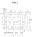
- Fig. 1 is a plan view showing a basic construction of the directionality reversed electrode structure of the surface acoustic wave device according to the invention.
- a positive electrode 11 comprises electrode fingers lla each having a width of ⁇ /8 and arranged at a pitch of ⁇
- a negative electrode 12 includes electrode fingers 12a each having a width of ⁇ /8 and arranged at a pitch of ⁇ .
- the positive electrode fingers 11a and negative electrode fingers 12a are arranged in an interdigital manner with an edge distance of ⁇ /8 viewed in a propagating direction of a surface acoustic wave.
- an aperture length A may be 200 ⁇ for lithium tetraborate substrate, said aperture length being defined as a length of portions of positive and negative electrode fingers 11a and 12a which are overlapped with each other viewed in the propagating direction of the surface acoustic wave.
- Figs. 2A and 2B illustrate exciting centers and reflecting centers of surface acoustic waves in SAW devices in which generally used regular or normal type electrode structure made of aluminum and gold, respectively on a usual piezoelectric substrate having no NSPUDT behavior, e.g. ST cut quartz substrate.
- a white arrow denotes an exciting center and a black arrow represents a reflecting center.
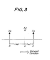
- the surface acoustic waves propagating in the left hand direction are cancelled out, while the surface acoustic waves propagating in the right hand direction are enhanced.
- Fig. 4 shows a principle of an operation of a device in which a regular or normal type electrode structure is provided on an STX + 25° quartz substrate having NSPUDT behavior which can be used in the surface acoustic wave device according to the invention.
- reflection centers X R are shifted in a right hand direction by ⁇ /8 due to an anisotropy of the NSPUDT substrate as compared with a case shown in Fig. 2. If the reflecting centers X R of the normal type electrode structure made of aluminum shown in Fig. 2A are shifted rightwardly, there is introduced a directivity in the right hand direction as shown in Fig. 4A in accordance with the principle explained above with reference to Fig. 3.
- NSPUDT substrates in the present invention it is possible to realize a desired operating property by providing normal type electrode structures including aluminum electrodes and gold electrodes on the substrate to be opposed to each other.
- the electrode structures on the same substrate are made different materials, a manufacturing process would be complicated, a yield is low and a cost is increased.
- signs of reflection coefficient for aluminum and gold electrode structures are identical with each other.
- the directionality reversed electrode structure illustrated in Fig. 1 is designed on the basis of the above mentioned principle.
- Fig. 6 is a schematic view representing a positional relationship between the exciting center X E and reflecting center X R in the electrode structure according to the invention.
- Fig. 6A denotes positions of the exciting center and reflecting center for a usual substrate such as STX cut quartz substrate having no NSPUDT behavior. From a distribution of a fundamental wave of a field distribution, it is seen that a position of the exciting center is shifted by - ⁇ /8 with respect to the center position of the positive electrode finger lla. Furthermore, from the total reflection coefficient, it can be seen that a position of the reflecting center X R is shifted by ⁇ /8 with respect to the center X 0 of the positive electrode finger 11a. This condition corresponds to the case of Fig. 2B.
- Fig. 6B shows a case in which the electrode structure is provided on a substrate having NSPUDT behavior such as STX + 25° cut quartz substrate. A position of the exciting center is not changed, but the reflecting center is shifted rightward by ⁇ /8 due to NSPUDT behavior of the substrate, so that a directionality oriented in the left hand direction can be attained.
- NSPUDT behavior such as STX + 25° cut quartz substrate.
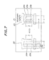
- Fig. 7 is a plan view showing a first embodiment of the surface acoustic wave device according to the invention constructed as a SAW filter using a surface acoustic wave having a wavelength ⁇ of 15 ⁇ m.
- a lithium tetraborate (Li 2 B 4 O 7 ) substrate 21 of Euler cut angles ( ⁇ , ⁇ , ⁇ ) (0°, 51°, 90°) providing an ideal NSPUDT behavior.
- transmitter side transducer 22 and receiver side transducer 23 made of an aluminum film having a thickness of 0.37 ⁇ m.
- the transmitter side transducer 22 is formed by a normal type electrode structure of ⁇ /4 including positive electrode fingers 22a and negative electrode fingers 22b having a width of ⁇ /4, i.e. 15/4 ⁇ m and being interdigitally arranged with an edge distance of ⁇ /4.
- the number of electrode pairs is 50.
- An aperture length A is 200 ⁇ , i.e. 15 ⁇ 200 ⁇ m.
- the receiver side transducer 23 is formed by the directionality reversed electrode structure shown in Fig. 1.
- This directionality reversed electrode structure includes positive and negative electrode fingers 23a and 23b having a width of ⁇ /8 and being arranged at a pitch of ⁇ with an edge distance of ⁇ /8 and floating electrodes 23c are inserted between successive negative electrode fingers 23b and positive electrode fingers 23a with an edge distance of ⁇ /8.
- An aperture length A of the directionality reversed electrode structure of the receiver side transducer 23 is also 200 ⁇ .
- Fig. 7 only one period of the electrode structures of the transmitter side transducer 22 and receiver side transducer 23 is shown for the sake of clearness.
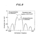
- Fig. 8 represents a conversion loss of the directionality reversed electrode structure of the receiver side transmitter 23 in the present embodiment.
- the surface acoustic wave transmitted by the transmitter side transducer 22 formed by the normal type electrode structure can be efficiently received, so that it is possible to provide a SAW filter having small insertion loss and ripple as well as a good phase characteristic.
- Fig. 9 is a schematic view representing a relationship between crystal axes and substrate coordinates of an STX + 25° cut quartz substrate having NSPUDT behavior.
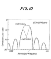
- Fig. 10 is a graph showing an conversion loss of a device in which a normal type electrode structure of ⁇ /4 is provided on such a quartz substrate
- Fig. 11 is a graph illustrating an conversion loss of a device according to the invention, in which the directionality reversed electrode structure is arranged on an STX + 25° cut quartz substrate having NSPUDT behavior.
- a solid line denotes a conversion loss in +x direction
- a broken line represents a conversion loss in -x direction.
- Fig. 12 is a plan view illustrating a second embodiment of the surface acoustic wave device according to the invention.
- a SAW filter is constructed by an STX + 25° cut quartz substrate 31, a transmitter side transducer 32 formed by a normal type electrode structure of ⁇ /4 and a receiver side transducer 33 formed by a directionality reversed electrode structure.
- the transmitter side transducer 32 and receiver side transducer 33 have the entirely same construction as the transducers 22 and 23 of the first embodiment shown in Fig. 7.
- Fig. 13 is a graph showing a theoretical insertion loss of the SAW filter of the present embodiment.
- Fig. 14 illustrates an insertion loss of a known SAW filter in which on an STX + 25° cut quartz substrate, there are provided a normal type electrode structure as the transmitter side transducer and a double electrode structure of ⁇ /8 as the receiver side transducer. By comparing these graphs, it is apparent that according to the invention there is substantially no ripple within a given frequency band and an insertion loss is very small.
- Figs. 15A is a plan view showing a normal type electrode structure of ⁇ /4 provided on an STX + 25° cut quartz substrate or a lithium tetraborate substrate of cut angles (0°, 51°, 90°) having NSPUDT behavior
- Fig. 15B is a cross sectional view thereof.
- a positive electrode 41 comprises electrode fingers 41a having a width of ⁇ /4 and being arranged at a pitch of ⁇
- a negative electrode 42 includes electrode fingers 42a having a width of ⁇ /4 and being arranged at a pitch of ⁇ .
- the positive and negative electrode fingers 41a and 42a are arranged interdigitally with and edge distance of ⁇ /4 viewed in a propagating direction of a surface acoustic wave.
- These electrode fingers 41a and 42a are made of aluminum.
- Fig. 15C shows positions of exciting centers and reflecting centers of a surface acoustic wave when a normal type electrode structure made of generally used aluminum is formed on a usual piezoelectric substrate having no NSPUDT behavior. It should be noted that Fig. 15c corresponds to Fig. 2A. As explained above with reference to Fig. 2A, a white arrow X E denotes the exciting center and a black arrow represents the reflecting center of the electrode finger. In the case of the normal type electrode structure, the positions of the exciting center and reflecting center are identical, so that the directivity does not occur in either right hand direction and left hand direction.
- Fig. 15E there is obtained a directivity in the left hand direction as has been explained with reference to Fig. 4B.
- Fig. 16 is a graph showing a conversion loss of a SAW device, in which the normal electrode structure of ⁇ /4 is provided on the STX + 25° cut quartz substrate having NSPUDT behavior.
- a frequency on an axis of abscissa is normalized by a center frequency of the surface acoustic wave transducer.
- An aperture length A is 250 ⁇ and the number of electrode pairs is 250.
- a conversion loss is theoretically calculated by a simulation while 250 pairs of split electrode structures are used as monitor electrodes.
- Fig. 17 is a graph showing a conversion loss of a SAW device using the above mentioned lithium tetraborate substrate having NSPUDT behavior.
- a conversion loss is theoretically calculated under a condition that an aperture length A is 200 ⁇ and the number of electrode pairs is 50.
- the piezoelectric substrate having NSPUDT behavior when used, it is possible to realize the directivity by using the normal type electrode structure.
- a SAW device such as a SAW filter
- Surface acoustic wave transducers having opposite directivities may be realized by making the transducers of different electrode materials such as aluminum and gold by utilizing a plurality of precise processes.
- the manufacturing process becomes complicated and a yield is liable to be decreased due to misalignment of pattern. Therefore, the SAW device is liable to be expensive in cost.
- reflection coefficients for aluminum and gold are identical with each other for some substrates, so that the above solution could not be adopted.
- the second aspect of the present invention can provide a novel directionality reversed electrode structure which can be advantageously used in combination of piezoelectric substrates having NSPUDT behavior.
- Figs. 18A and 18B are plan and cross sectional views, respectively showing a first embodiment of the surface acoustic wave device according to the second aspect of the invention.
- a directionality reversed electrode structure comprising positive electrode 51, negative electrode 52 and floating electrode 53 is provided on an STX + 25° cut quartz substrate.
- Positive electrode fingers 51a and negative electrode fingers 52a are arranged at a pitch of ⁇ and have a width of ⁇ /8.
- the positive electrode fingers 51a and negative electrode fingers 52a are arranged interdigitally such that a distance between centers of successive positive and negative electrode fingers is about ⁇ /2.
- the floating electrode 53 includes floating electrode fingers 53a having a width of about ⁇ /4 and each of the floating electrode fingers is interposed between successive positive electrode finger 51a and negative electrode finger 52a with an edge distance of about ⁇ /16. Within an electrode pair, two floating electrode fingers 53a are connected to each other by means of a bridge portion 53b. All the positive and negative electrodes 51 and 52 and floating electrode 53 are made of aluminum and have a same thickness as shown in Fig. 18B.
- Fig. 18C denotes positions of exciting and reflecting centers for a SAW device in which the above mentioned electrode structure shown in Figs. 18A and 18B is provided on a piezoelectric substrate having no NSPUDT behavior.
- Fig. 18D shows positions of exciting and reflecting centers of the SAW transducer of the present embodiment. As shown in Figs. 18C and 18D, there appear two reflecting centers X R1 and X R2 . In the present embodiment, a width of the floating electrode 53a is wider than that of the positive and negative electrode fingers 51a and 52a as illustrated in Fig. 18A. Then, reflection coefficients have a relationship of X R1 >X R2 .
- Fig. 18C denotes positions of exciting and reflecting centers for a SAW device in which the above mentioned electrode structure shown in Figs. 18A and 18B is provided on a piezoelectric substrate having no NSPUDT behavior.
- Fig. 18D shows positions of exciting and reflecting centers of the SAW transducer of the present embodiment
- Fig. 18E is equivalent to Fig. 15E.
- the SAW transducer of the present embodiment reveals a directivity in the left direction.
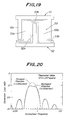
- Fig. 19 is a plan view illustrating a second embodiment of the SAW device according to the second aspect of the invention.
- the construction of the floating electrode 53 is modified. That is, in the first embodiment, the first floating electrode finger 53a arranged between the positive finger and the negative finger viewed in the propagating direction of the surface acoustic wave and the second floating electrode finger 53b arranged between the negative finger 52a and the positive finger 51a also viewed in the propagating direction of the surface acoustic wave are couple with each other by the bridge portion 53b, but the floating electrodes 53 in successive electrode pairs are not connected to each other.
- all the floating electrode fingers 53a are connected to each other via the bridge portions 53b. That is, all the floating electrodes 53 are shortcircuited.
- Fig. 20 is a graph showing a conversion loss of the first and second embodiments of the surface acoustic wave device according to the invention.
- a conversion loss is theoretically calculated under conditions that the number of electrode pairs is 250, an aperture length A is 250 ⁇ , and all the electrodes are formed by an aluminum film having a thickness of 0.01 ⁇ .
- -x direction is the forward direction which is opposite to that of the case shown in Fig. 16.
- Figs. 21A and 21B are plan and cross sectional views, respectively showing a third embodiment of the surface acoustic wave device according to the second aspect of the invention.
- fingers 51a of a positive electrode 51 and fingers 52a of a negative electrode 52 have a width of about ⁇ /5 and are arranged at a pitch of about ⁇ such that centers of successive positive and negative electrode fingers 51a and 52a are separated from each other by a distance of ⁇ /2.
- Fingers 53a of a floating electrode 53 have a width of about ⁇ /5 and are arranged symmetrically between successive positive fingers 51a and negative fingers 52a with an edge distance of about ⁇ /20.
- the two floating electrode fingers 53a within an electrode pair are coupled with each other by means of a bridge portion 53b. Since gaps between the positive and negative electrode fingers 51a and 52a and the floating electrode fingers 53a are very small such as ⁇ /20, this type of the electrode structure is called a narrow gap type.
- a thickness of the floating electrode fingers 53a is larger than a thickness of the positive and negative electrode fingers 51a and 52a as illustrated in Fig. 21B, and all the electrodes are made of aluminum. Then, X R1 > X R2 , and therefore a directivity in the left hand direction can be attained as illustrated in Fig. 21E. It should be noted that Figs. 21C and 21D correspond to Figs. 18C and 18D, respectively.
- the floating electrode 53 is made of a material whose reflection coefficient differs from that of the positive and negative electrodes 51 and 52, a similar result could be obtained.
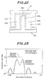
- Fig. 22 is a plan view depicting a fourth embodiment of the surface acoustic device according to the second aspect of the invention.
- all the floating electrode fingers 53b are connected with each other by means of the bridge portions 53b.
- the remaining construction of the present embodiment is similar to the third embodiment shown in Figs. 21A and 21B.
- the floating electrode fingers 53a are arranged symmetrically, and thus operating characteristics of the fourth embodiment shown in Fig. 22 is substantially identical with those of the second embodiment illustrated in Fig. 20.
- Fig. 23 shows a conversion loss of the third and fourth embodiments depicted in Figs. 21 and 22.
- a conversion loss is theoretically calculated under conditions that the number of pairs is 250, an aperture length A is 250 ⁇ , a thickness of the positive and negative electrodes 51 and 52 is 0.01 ⁇ , and a thickness of the floating electrode 53 is 0.02 ⁇ .
- the directivity is obtained such that the forward direction is -x direction. Like as the first and second embodiments shown in Figs. 18 and 19, the directivity is reversed.
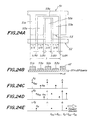
- Figs. 24A and 24B are plan and cross sectional views, respectively showing a fifth embodiment of the surface acoustic wave device according to the second aspect of the present invention.
- the present embodiment differs from the fourth embodiment shown in Fig. 21 in a point that a thickness of the positive and negative electrodes 51 and 52 is larger than a thickness of the floating electrode 53 as shown in Fig. 24B.
- the reflecting coefficients have a relationship of X R2 >X R1 . Therefore, a directivity becomes opposite as shown in Fig. 24E. That is, the directivity in the right hand direction like the normal type electrode structure of ⁇ /4 shown in Fig. 15D.
- the electrode structure of the present embodiment could not be utilized in combination with the normal type electrode structure, but may be advantageously used together with the electrode structures of the third and fourth embodiments shown in Figs. 21 22.
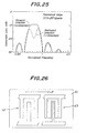
- Fig. 25 shows a conversion loss of the fifth embodiment illustrated in Fig. 24.
- a conversion loss is theoretically calculated under conditions that the number of electrode pairs is 250 ⁇ , an aperture length A is 250 ⁇ , a thickness of the aluminum positive and negative aluminum electrodes 51 and 52 is 0.02 ⁇ , and a thickness of the floating electrode 53 made of aluminum is 0.01 ⁇ .
- Fig. 26 is a plan view depicting an embodiment of a SAW filter according to the invention.
- a transmitter side transducer 62 formed by the normal type electrode structure of ⁇ /4 shown in Fig. 15 and a receiver side transducer 63 formed by the directionality reversed electrode structure shown in Fig. 19.
- Fig. 27 is a plan view illustrating another embodiment of the SAW filter according to the invention.
- a transmitter side transducer 62 constructed by the normal type electrode structure of ⁇ /4 like as the previous embodiment and a receiver side transducer 64 formed by the directionality reversed electrode structure shown in Fig. 19.
- Fig. 28 is a plan view depicting another embodiment of the SAW filter according to the invention.
- a transmitter side transducer 65 formed by the narrow gap type electrode structure shown in Fig. 24 by connecting all the floating electrode fingers by the bridge portions and a receiver side transducer 66 constructed by the directionality reversed electrode structure illustrated in Fig. 22.
- the transmitter side transducer 65 has the directivity which is identical with that of the normal type electrode structure of ⁇ /4, and therefore it is possible to realize the SAW filter having good characteristics by combining the transducer 65 with the directionality reversed electrode structure shown in Fig. 22.
- the surface acoustic wave transmitted from the transmitter side transducer 65 can be efficiently received by the receiver side transducer 66, so that a insertion loss is small, a ripple is also small, and center frequencies are coincided with each other.
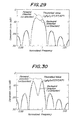
- Fig. 29 is a graph representing a conversion loss of a sixth embodiment of the surface acoustic transducer according to the invention, in which on a lithium tetraborate substrate of Euler angles (0°, 51°, 90°) which reveals an ideal NSPUDT behavior, there is provided the directionality reversed electrode structure shown in Fig. 18.
- a conversion loss is theoretically calculated under conditions that all the electrode fingers are formed by an aluminum film having a thickness of 0.025 ⁇ , an aperture length A is 200 ⁇ , and the number of electrode pairs is 50.
- Fig. 30 is a graph showing a conversion loss of a seventh embodiment of the surface acoustic transducer according to the invention, in which on the above mentioned lithium tetraborate substrate having an ideal NSPUDT behavior, there is provided the narrow gap type directionality reversed electrode structure shown in Fig. 21.
- a conversion loss is theoretically calculated under conditions that the positive and negative electrode fingers are formed by an aluminum film having a thickness of 0.025 ⁇ , the floating electrode fingers are formed by an aluminum film having a thickness of 0.05 ⁇ , an aperture length A is 200 ⁇ , and the number of electrode pairs is 50.
- Fig. 31 is a graph representing a conversion loss of an eighth embodiment of the surface acoustic transducer according to the invention, in which on the above mentioned lithium tetraborate substrate having an ideal NSPUDT behavior, there is provided the narrow gap type directionality reversed electrode structure shown in Fig. 24.
- a conversion loss is theoretically calculated under conditions that the positive and negative electrode fingers are formed by an aluminum film having a thickness of 0.05 ⁇ , the floating electrode fingers are formed by an aluminum film having a thickness of 0.025 ⁇ , an aperture length A is 200 ⁇ , and the number of electrode pairs is 50. From this graph, it can be seen that the present invention reveals the directivity which is the same as the normal type transducer of ⁇ /4.
- Figs. 32A and 32B are plan and cross sectional views, respectively showing a ninth embodiment of the surface acoustic wave transducer according to the second aspect of the invention.
- positive electrode 71 and negative electrode 72 on an STX + 25° cut quartz substrate.
- Positive electrode fingers 71a and negative electrode fingers 72a each having a width of about ⁇ /4 are arranged interdigitally at a pitch of ⁇ while centers of successive fingers is separated by a distance of ⁇ /2.
- Floating electrode fingers 73a having a width of about ⁇ /4 are arranged between successive positive and negative electrode fingers 71a and 72a with interposing narrow gaps therebetween. Therefore, the transducer of the present invention is of the narrow gap type. All the floating electrode fingers 73a are connected to each other by means of bridge portions 73b.
- all the electrodes are made of aluminum and a thickness of the floating electrode fingers 73a is larger than a thickness of the positive and negative electrode fingers 71a and 72a as illustrated in Fig. 32B.
- the gaps between successive electrode fingers 71a, 72a and 73a are filled with aluminum oxide film 74 formed by an anodic oxidization, so that there electrode fingers are electrically isolated by the aluminum oxide film 74 serving as a dielectric material.
- a size of the gap g between the positive and negative electrode fingers 71a and 72a and floating electrode fingers 73a is determined by a thickness of the aluminum oxide film 74 and is generally smaller than 1 ⁇ m. As shown in Fig.
- the directivity of the surface acoustic wave device of the present embodiment is opposite to the directivity of the normal type electrode structure of ⁇ /4. It should be noted that Figs. 32C and 32D correspond to Figs. 18C and 18D, respectively.
- Figs. 33A and 33B are plan and cross sectional views, respectively showing a tenth embodiment of the surface acoustic wave transducer according to the second aspect of the invention.
- positive electrode 81 and negative electrode 82 on an STX + 25° cut quartz substrate, there are provided positive electrode 81 and negative electrode 82.
- Positive electrode fingers 81a and negative electrode fingers 82a each having a width of about ⁇ /8 are arranged interdigitally at a pitch of ⁇ while centers of successive fingers is separated by a distance of ⁇ /2.
- Floating electrode fingers 83a having a width of about ⁇ /8 are arranged between successive positive and negative electrode fingers 81a and 82a with an edge distance of about ⁇ /8. All the floating electrode fingers 83a are connected to each other by means of bridge portions 83b.
- the positive and negative electrode fingers 81a and 82a are formed by an aluminum film having a thickness t 1 and the floating electrode fingers 83a are made of a laminated film of an aluminum film having a thickness of t 1 and a chromium film having a thickness of t 2 .
- Such an electrode structure can be manufactured easily by means of the above mentioned selective etching due to electrochemical effect. That is, after successively applying an aluminum film and a chromium film over a whole surface, both the aluminum and chromium films are removed by a photolithography at portions except for the electrodes.
- the substrate is immersed into an etchant while a voltage is applied to the positive and negative electrodes 81 and 82 to remove only the chromium film on the positive and negative electrodes due to the electrochemical effect.
- the electrode structure shown in Fig. 33B is obtained. It is also possible to use an etchant by means of which a chromium film to which a voltage is not applied is selectively removed. Then, a voltage is applied only to the floating electrode 83. In either cases, a desired electrode structure can be manufactured by only one photolithographic process.
- the surface acoustic wave transducer has the directivity opposite to that of the normal type electrode structure of ⁇ /4 as illustrated in Fig. 33E.
- Figs. 33C and 33D show positions of the exciting and reflecting centers like Figs. 18C and 18D, respectively.
- Fig. 34 is a plan view showing an eleventh embodiment of the surface acoustic wave device according to the second aspect of the invention.
- the present embodiment differs from the tenth embodiment illustrated in Fig. 33 only in a point that all the floating electrode fingers 83a of the floating electrode 83 are not coupled with each other. Within respective electrode pairs, two floating electrode fingers 83 are connected to each other by means of the bridge portion 83b.
- the surface acoustic wave device of the present embodiment has same characteristics as those of the tenth embodiment.
- the piezoelectric substrate having NSPUDT behavior is formed by the (0°, 51°, 90°) cut lithium tetraborate single crystal substrate and STX + 25° cut quartz substrate.
- the piezoelectric substrates having NSPUDT behavior it is possible to use any kind of piezoelectric substrates having NSPUDT behavior.
- piezoelectric substrates other than lithium tetraborate substrate and quartz.
- YZ + 51.25° cut lithium tantalate (LiTaO 3 ) substrate, Y- ⁇ X ( ⁇ 25°-45°) cut lithium niobate substrate and 128° rotated Y cut lithium niobate substrate.
- These substrates have been known to have NSPUDT behavior.
- the object of the present invention could be attained although width, pitch, edge distance and thickness of electrodes deviate from the above mentioned values by about ⁇ 10% error during precise machinings. Moreover, if the directivity deviates from a desired one due to a material and cut angles of a substrate, this deviation can be corrected by slightly shifting a position of the floating electrode.
- all the floating electrode fingers are coupled with each other or the two floating electrodes within respective electrode pairs are coupled with each other. According to the invention, all the floating electrodes may be separated from each other to form the opened-type floating electrode.
- the electrode structure having the reversed directivity can be realized on the substrate having NSPUDT behavior, so that it is possible to obtain the surface acoustic wave device having a low loss and a good phase characteristic.
- the electrode structure can be manufactured by only one process, so that the manufacturing process is simple, a yield is improved and cost is reduced.
- the manufacture becomes very simple and a desired size can be easily realized. Therefore, an insertion loss can be decreased and frequency and phase characteristics can be also improved.
- the directionality reversed electrode structure is constructed under a basic dimension of ⁇ /8 which is sufficiently large than ⁇ /12 of a known directionality reversed electrode structure. Therefore, the directionality reversed electrode structure according to the invention can be manufactured easily and precisely.
- the directivity can be reversed. Therefore, in a SAW filter, characteristics of the transmitter side transducer and receiver side transducer can be matched with each other, so that the center frequencies of these transducers can be easily made coincided with each other.
Landscapes
- Physics & Mathematics (AREA)
- Acoustics & Sound (AREA)
- Surface Acoustic Wave Elements And Circuit Networks Thereof (AREA)
Claims (19)
- Dispositif à ondes acoustiques de surface comprenant :un substrat piézoélectrique ayant des angles de coupe de telle sorte que le substrat révèle un comportement de transducteur unidirectionnel monophasé naturel ; etune structure d'électrode à directionnalité inversée formée sur une surface dudit substrat piézoélectrique et possédant une structure de base dans laquelle des dents d'électrodes positive et négative chacune d'une largeur d'environ λ/8, λ étant une longueur d'onde d'une onde acoustique de surface, sont agencées successivement avec une distance de bord d'environ λ/8, et des dents d'électrode flottante chacune d'une largeur d'environ 3λ/8 sont agencées avec une distance de bord d'environ λ/8 par rapport aux dents d'électrode positive, où λ est une longueur d'onde d'une onde acoustique de surface, et lesdites dents d'électrodes positive et négative peuvent être connectées à deux bornes d'une source de signaux ou d'une charge ayant une différence de phase de 180°.
- Dispositif à ondes acoustiques de surface selon la revendication 1, où ledit substrat piézoélectrique est formé par un substrat sélectionné dans le groupe constitué d'un substrat en quartz à coupe STX+25°, d'un substrat en quartz à coupe (45°, 55°, O°), d'un substrat de tantalate de lithium (LiTaO3) à coupe YZ + 51,25°, d'un substrat en niobate de lithium (LiNbO3) à coupe de Y-X ( = 25°-45°), d'un substrat en niobate de lithium à coupe Y tournée de 128° et d'un substrat en tétraboate de lithium (Li2B4O7) dont les angles de coupe représentés par des angles d'Euler (ψ, , ) satisfont ψ = -5° - +5°, = 9°-29°, 32°-86° et = 85°-95°.
- Dispositif à ondes acoustiques de surface selon la revendication 1, formé comme filtre à ondes acoustiques de surface, où ladite structure d'électrode à directionnalité inversée est prévue sur le substrat comme transducteur côté récepteur, et le dispositif comprend en outre un transducteur côté transmetteur formé par une structure d'électrode de type normal, dans laquelle les dents d'électrode positive et les dents d'électrode négative, chacune d'une largeur d'environ λ/4, sont agencées d'une manière interdigitée, avec une distance de bord d'environ λ/4.
- Dispositif à ondes acoustiques de surface selon la revendication 3, où ledit substrat piézoélectrique est formé par un substrat en quartz à coupe STX+25°.
- Dispositif à ondes acoustiques de surface selon la revendication 3, où ledit substrat piézoélectrique est formé par un substrat en tétraborate de lithium ayant des angles de coupe représentés par des angles d'Euler (ψ, , ) de ψ = -5° - +5°, = 9°-29°, 32°-86° et = 85°-95°.
- Dispositif à ondes acoustiques de surface comprenant :un substrat piézoélectrique ayant de tels angles de coupe que le substrat révèle un comportement de transducteur unidirectionnel monophasé naturel ; etune structure d'électrode incluant des dents d'électrodes positive et négative agencées alternativement avec un pas de λ alors qu'une distance entre les centres des dents successives des électrodes positive et négative est de λ/2, et des dents de l'électrode flottante sont agencées chacune entre des dents successives des électrodes positive et négative et possédant un coefficient de réflexion qui diffère de celui des dents d'électrodes positive et négative, où λ est une longueur d'onde d'une onde acoustique de surface, et lesdites dents d'électrodes positive et négative doivent être connectées à deux bornes d'une source de signaux ou d'une charge ayant une différence de phase de 180°.
- Dispositif à ondes acoustiques de surface selon la revendication 6, où lesdites dents de l'électrode flottante sont agencées symétriquement dans des paires d'électrodes respectives.
- Dispositif à ondes acoustiques de surface selon la revendication 6, où une largeur desdites dents des électrodes positive et négative est d'environ λ/8, et lesdites dents de l'électrode flottante ont une largeur d'environ λ/4 et sont agencées entre des dents successives des électrodes positive et négative , avec une distance de bord d'environ λ/16.
- Dispositif à ondes acoustiques de surface selon la revendication 8, où toutes les dents de ladite électrode flottante sont reliées les unes aux autres par des portions de pont.
- Dispositif à ondes acoustiques de surface selon la revendication 8, où lesdites dents de l'électrode flottante dans les paires d'électrodes respectives sont reliées les unes aux autres.
- Dispositif à ondes acoustiques de surface selon la revendication 6, où une largeur desdites dents des électrodes positive et négative est d'environ λ/4, et lesdites dents de l'électrode flottante sont agencées entre des dents de l'électrode positive et des dents de l'électrode négative successives de telle sorte que les bords des dents de l'électrode flottante sont opposés aux bords des dents des électrodes positive et négative, en interposant entre celles-ci de très petits entrefers ou un matériau diélectrique, et lesdites dents de l'électrode flottante sont formées par un film métallique réalisé dans le même matériau que celui des dents des électrodes positive et négative mais ayant une épaisseur qui diffère de celle des dents des électrodes positive et négative.
- Dispositif à ondes acoustiques de surface selon la revendication 6, où une largeur desdites dents des électrodes positive et négative est d'environ λ/4, et lesdites dents de l'électrode flottante sont agencées entre des dents successives de l'électrode positive et des dents de l'électrode négative de telle sorte que les bords des dents de l'électrode flottante sont opposés aux bords des dents des électrodes positive et négative en interposant entre ceux-ci de très petits entrefers ou un matériau diélectrique, et lesdites dents de l'électrode flottante sont formées par un film métallique laminé incluant un film métallique réalisé en un matériau différent de celui des dents des électrodes positive et négative.
- Dispositif à ondes acoustiques de surface selon la revendication 6, où une largeur desdites dents des électrodes positive et négative est d'environ λ/5, et lesdites dents de l'électrode flottante sont agencées entre des dents successives des électrodes positive et négative de telle sorte que les bords des dents de l'électrode flottante sont opposés aux bords des dents des électrodes positive et négative en interposant entre ceux-ci de très petits entrefers ou un matériau diélectrique, et lesdites dents de l'électrode flottante sont formées par un film métallique réalisé dans le même matériau que celui des dents des électrodes positive et négative mais ayant une épaisseur différente de celle des dents des électrodes positive et négative.
- Dispositif à ondes acoustiques de surface selon la revendication 6, où une largeur desdites dents des électrodes positive et négative est d'environ λ/5, et lesdites dents de l'électrode flottante sont agencées entre les dents successives des électrodes positive et négative de telle sorte que les bords des dents de l'électrode flottante sont opposés aux bords des dents des électrodes positive et négative, en interposant entre ceux-ci des entrefers très étroits ou un matériau diélectrique, et lesdites dents de l'électrode flottante sont formées par un film métallique laminé incluant un film métallique réalise en un matériau différent de celui des dents des électrodes positive et négative.
- Dispositif à ondes acoustiques de surface selon la revendication 6, où une largeur desdites dents des électrodes positive et négative est d'environ λ/8, lesdites dents de l'électrode flottante ont une largeur d'environ λ/8 et sont agencées entre des dents successives des électrodes positive et négative, avec une distance de bord d'environ λ/8, et lesdites dents de l'électrode flottante sont constituées par un film métallique réalisé dans le même matériau que celui des dents des électrodes positive et négative mais ayant une épaisseur différente de celle des dents des électrodes positive et négative.
- Dispositif à ondes acoustiques de surface selon la revendication 6, où une largeur desdites dents des électrodes positive et négative est d'environ λ/8, lesdites dents de l'électrode flottante ont une largeur d'environ λ/8 et sont agencées entre des dents successives des électrodes positive et négative, avec une distance de bord d'environ λ/8, et lesdites dents de l'électrode flottante sont formées par un film métallique laminé comprenant un film métallique réalisé en un matériau différent de celui des dents des électrodes positive et négative.
- Dispositif à ondes acoustiques de surface selon la revendication 6, où ledit substrat piézoélectrique est formé par un substrat sélectionné dans le groupe constitué d'un substrat en quartz à coupe STX+25°, d'un substrat en quartz à coupe (45°, 55°, 0°), d'un substrat en tantalate de lithium (LiTaO3) à coupe YZ + 51,25°, d'un substrat en niobate de lithium (LiNbO3) à coupe Y-X ( = 25°-45°) d'un substrat en niobate de lithium à coupe Y tourné de 128° et d'un substrat en tétraborate de lithium (Li2B4O7) dont les angles de coupe représentés par des angles d'Euler (ψ, , ) satisfont ψ = -5° - +5°, = 9°-29°, 32°-86° et = 85°-95°.
- Dispositif à ondes acoustiques de surface selon la revendication 6, formé comme filtre à ondes acoustiques de surface, où ladite structure d'électrode est prévue sur le substrat comme un transducteur côté récepteur ou transmetteur, et le dispositif comprend en outre un transducteur côté transmetteur ou récepteur formé par une structure d'électrode de type normal, dans laquelle les dents de l'électrode positive et les dents de l'électrode négative, chacune d'une largeur d'environ λ/4, sont agencées d'une manière interdigitée avec une distance de bord d'environ λ/4.
- Dispositif à ondes acoustiques de surface selon la revendication 6, formé comme un filtre à ondes acoustiques de surface, où ladite structure d'électrode est prévue sur le substrat comme transducteur côté transmetteur ou récepteur, et le dispositif comprend en outre un transducteur côté récepteur ou transmetteur constitué par une seconde structure d'électrode ayant une construction correspondant à celle de ladite structure d'électrode mais ayant une directivité opposée à celle de ladite structure d'électrode.
Applications Claiming Priority (9)
| Application Number | Priority Date | Filing Date | Title |
|---|---|---|---|
| JP23355094A JP3484237B2 (ja) | 1994-09-28 | 1994-09-28 | 弾性表面波デバイス |
| JP23355094 | 1994-09-28 | ||
| JP233550/94 | 1994-09-28 | ||
| JP6260488A JP3014930B2 (ja) | 1994-10-25 | 1994-10-25 | 弾性表面波デバイス |
| JP26048894 | 1994-10-25 | ||
| JP260488/94 | 1994-10-25 | ||
| JP804895 | 1995-01-23 | ||
| JP7008048A JP3040928B2 (ja) | 1995-01-23 | 1995-01-23 | 弾性表面波トランスデューサ |
| JP8048/95 | 1995-01-23 |
Publications (3)
| Publication Number | Publication Date |
|---|---|
| EP0704967A2 EP0704967A2 (fr) | 1996-04-03 |
| EP0704967A3 EP0704967A3 (fr) | 1997-08-27 |
| EP0704967B1 true EP0704967B1 (fr) | 2001-08-08 |
Family
ID=27277852
Family Applications (1)
| Application Number | Title | Priority Date | Filing Date |
|---|---|---|---|
| EP95306381A Expired - Lifetime EP0704967B1 (fr) | 1994-09-28 | 1995-09-12 | Dispositif à ondes acoustiques de surface |
Country Status (3)
| Country | Link |
|---|---|
| US (1) | US5773911A (fr) |
| EP (1) | EP0704967B1 (fr) |
| DE (1) | DE69522066T2 (fr) |
Families Citing this family (21)
| Publication number | Priority date | Publication date | Assignee | Title |
|---|---|---|---|---|
| DE69522066T2 (de) * | 1994-09-28 | 2002-03-28 | Ngk Insulators, Ltd. | Akustische Oberflächenwellenanordnung |
| JP3268179B2 (ja) * | 1995-11-08 | 2002-03-25 | 正男 竹内 | 弾性表面波変換器及びこの変換器を用いた弾性表面波フィルタ |
| DE69712654T2 (de) * | 1996-02-22 | 2002-09-05 | Seiko Epson Corp., Tokio/Tokyo | Tintenstrahlaufzeichnungskopf, Tintenstrahlaufzeichnungsgerät damit versehen und Herstellungsverfahren eines Tintenstrahlaufzeichnungskopfes |
| JPH10256870A (ja) * | 1997-03-14 | 1998-09-25 | Ngk Insulators Ltd | 弾性表面波デバイス |
| AU8488398A (en) * | 1997-07-16 | 1999-02-10 | Sawtek, Inc. | An optimal cut for saw devices on quartz |
| DE19907640A1 (de) * | 1998-03-25 | 1999-10-07 | Dresden Ev Inst Festkoerper | Akustisches Oberflächenwellenbauelement |
| JP3291255B2 (ja) * | 1998-09-22 | 2002-06-10 | 日本碍子株式会社 | 弾性表面波デバイス |
| US6420815B1 (en) * | 1999-09-16 | 2002-07-16 | Sanyo Electric Co., Ltd. | Substrate for surface acoustic wave device and surface acoustic wave device |
| US6242844B1 (en) * | 1999-12-28 | 2001-06-05 | Cts Corporation | Wide-band single-phase unidirectional transducer |
| DE10041040A1 (de) * | 2000-08-22 | 2002-03-07 | Zeiss Carl | Vorrichtung und Verfahren zur Belichtung einer strahlungsempfindlichen Schicht mittels geladener Teilchen sowie Maske hierfür |
| GB0024853D0 (en) * | 2000-10-11 | 2000-11-22 | Morgan David P | Transducers for surface acoustic wave devices |
| DE10113788A1 (de) | 2001-03-21 | 2002-09-26 | Zeiss Carl | Beugungsoptische Komponente, Beleuchtungssystem und Belichtungssystem mit einer solchen beugungsoptischen Komponente und Belichtungsverfahren unter Verwendung eines solchen Belichtungssystems |
| JP2003124778A (ja) * | 2001-10-05 | 2003-04-25 | Samsung Electro Mech Co Ltd | 一方向性弾性表面波変換器 |
| WO2003065575A2 (fr) * | 2002-01-25 | 2003-08-07 | Michigan State University | Dispositifs a ondes acoustiques de surface a base de diamant nanocristallin non poli |
| RU2195069C1 (ru) * | 2002-04-08 | 2002-12-20 | Зао Нпп "Элко" | Однонаправленный преобразователь поверхностных акустических волн |
| US7233095B2 (en) * | 2002-06-26 | 2007-06-19 | Lg Innotek Co., Ltd. | Single crystal substrate and cutting method thereof |
| JP4182157B2 (ja) * | 2002-08-12 | 2008-11-19 | 株式会社村田製作所 | 表面波装置 |
| CA2542328A1 (fr) * | 2003-10-08 | 2005-04-21 | Rf Saw Components, Incorporated | Transducteur unidirectionnel monophase a onde acoustique de surface, et reflecteurs ameliores |
| DE102010041973B4 (de) * | 2010-10-05 | 2015-04-16 | Leibniz-Institut Für Festkörper- Und Werkstoffforschung Dresden E.V. | Bauelement auf der Basis akustischer Oberflächenwellen |
| CN205992889U (zh) * | 2014-03-31 | 2017-03-01 | 株式会社村田制作所 | 声表面波滤波器 |
| US12494768B2 (en) * | 2021-12-28 | 2025-12-09 | Murata Manufacturing Co., Ltd. | Transversely-excited film bulk acoustic resonators with gap dielectric stripes in busbar-electrode gaps |
Family Cites Families (23)
| Publication number | Priority date | Publication date | Assignee | Title |
|---|---|---|---|---|
| US3686518A (en) * | 1970-09-02 | 1972-08-22 | Clinton S Hartmann | Unidirectional surface wave transducers |
| US4087714A (en) * | 1971-10-18 | 1978-05-02 | Hazeltine Corporation | Three phase unidirectional transducer |
| US3748603A (en) * | 1972-03-27 | 1973-07-24 | Zenith Radio Corp | Surface wave filter with reflection suppression |
| FR2290786A1 (fr) * | 1974-11-08 | 1976-06-04 | Thomson Csf | Dispositif a reflexion selective d'ondes elastiques de surface |
| US4006438A (en) * | 1975-08-18 | 1977-02-01 | Amp Incorporated | Electro-acoustic surface-wave filter device |
| US4353046A (en) * | 1980-11-04 | 1982-10-05 | R F Monolithics, Inc. | Surface acoustic wave device with reflectors |
| JPS57103420A (en) * | 1980-12-18 | 1982-06-28 | Toko Inc | Grouped unidirectional surface acoustic wave transducer |
| US4521711A (en) * | 1982-04-14 | 1985-06-04 | Clarion Co., Ltd. | Unidirectional transducer for a surface-acoustic-wave device and a method of making same |
| US4910839A (en) * | 1984-12-03 | 1990-03-27 | R.F. Monolithics, Inc. | Method of making a single phase unidirectional surface acoustic wave transducer |
| US4818961A (en) * | 1987-04-15 | 1989-04-04 | Hitachi, Ltd. | Surface acoustic wave filter with capacitive phase shifter |
| JPH0244169A (ja) * | 1988-08-04 | 1990-02-14 | Nippon Kentetsu Co Ltd | 冷蔵オープンショーケースの運転制御方法 |
| JP2709520B2 (ja) * | 1988-10-16 | 1998-02-04 | 和彦 山之内 | 電極指間ギャップ微小な弾性表面波変換器の構造及びその製造方法 |
| JP3107381B2 (ja) * | 1989-05-26 | 2000-11-06 | 株式会社日立製作所 | 弾性表面波デバイス |
| US5051644A (en) * | 1990-04-19 | 1991-09-24 | R. F. Monolithics, Inc. | Electrode structure with constant velocity and predetermined reflectivity |
| JP3096102B2 (ja) * | 1991-08-29 | 2000-10-10 | 和彦 山之内 | 弾性表面波フィルタ装置 |
| FR2682833B1 (fr) * | 1991-10-18 | 1993-12-03 | Thomson Csf | Filtre a ondes de surface et a trajet acoustique replie. |
| JP3244094B2 (ja) * | 1992-03-13 | 2002-01-07 | キンセキ株式会社 | 弾性表面波装置 |
| JP3363937B2 (ja) * | 1992-03-26 | 2003-01-08 | 日本碍子株式会社 | 弾性表面波フィルタ装置 |
| JPH05328736A (ja) * | 1992-05-15 | 1993-12-10 | Yuasa Corp | 三相インバータの制御回路 |
| DE4330438B4 (de) * | 1992-09-09 | 2010-07-01 | Hitachi, Ltd. | Oberflächenakustikwelleneinrichtung |
| FR2695771B1 (fr) * | 1992-09-15 | 1994-10-28 | Thomson Csf | Transducteur d'ondes unidirectionnel. |
| DE69522066T2 (de) * | 1994-09-28 | 2002-03-28 | Ngk Insulators, Ltd. | Akustische Oberflächenwellenanordnung |
| US5545940A (en) * | 1994-11-07 | 1996-08-13 | Rf Monolithics, Inc. | Multitrack transversely folded surface acoustic wave structure |
-
1995
- 1995-09-12 DE DE69522066T patent/DE69522066T2/de not_active Expired - Fee Related
- 1995-09-12 EP EP95306381A patent/EP0704967B1/fr not_active Expired - Lifetime
-
1997
- 1997-07-29 US US08/901,277 patent/US5773911A/en not_active Expired - Fee Related
Also Published As
| Publication number | Publication date |
|---|---|
| DE69522066D1 (de) | 2001-09-13 |
| EP0704967A3 (fr) | 1997-08-27 |
| US5773911A (en) | 1998-06-30 |
| DE69522066T2 (de) | 2002-03-28 |
| EP0704967A2 (fr) | 1996-04-03 |
Similar Documents
| Publication | Publication Date | Title |
|---|---|---|
| US5773911A (en) | Surface acoustic wave device | |
| KR100303636B1 (ko) | 탄성표면파필터 | |
| EP0704966B1 (fr) | Dispositif à ondes acoustiques de surface | |
| US5438306A (en) | Surface acoustic wave filter device with symmetrical electrode arrangement | |
| KR20030051385A (ko) | 표면탄성파소자 및 그것을 구비한 듀플렉서 | |
| EP0865156A2 (fr) | Dispositif à ondes acoustiques de surface comportant un substrat de langasite monocristallin | |
| US6194809B1 (en) | Surface acoustic wave device comprising langasite single crystal substrate | |
| EP1120908A1 (fr) | Dispositif a onde elastique | |
| EP0562876B1 (fr) | Dispositif de filtrage à ondes acoustiques de surface | |
| US6246150B1 (en) | Surface acoustic wave device | |
| EP0802627B1 (fr) | Convertisseur d'ondes sonores de surface et dispositif de filtrage acoustique l'utilisant | |
| KR100889231B1 (ko) | 탄성경계파 장치 | |
| JPH03133209A (ja) | 一方向性sawフィルタ | |
| JP2002141768A (ja) | 表面弾性波素子 | |
| JP3040928B2 (ja) | 弾性表面波トランスデューサ | |
| JP3014930B2 (ja) | 弾性表面波デバイス | |
| GB2120892A (en) | Surface-acoustic-wave device unidirectional transducer | |
| JP3197883B2 (ja) | 弾性表面波トランスデューサ | |
| JP4379143B2 (ja) | トランスバーサル型弾性表面波フィルタ | |
| JPH053930B2 (fr) | ||
| WO2026075153A1 (fr) | Dispositif à ondes élastiques, substrat piézoélectrique, dispositif de communication et procédé de fabrication de substrat piézoélectrique | |
| JP2583384B2 (ja) | 内部反射形一方向性弾性表面波変換器及びこれを用いた電子装置 | |
| JPS621310A (ja) | 弾性表面波装置 | |
| JPH06152309A (ja) | 一方向性弾性表面波変換器及びこれを用いた 電子装置 | |
| JP4506394B2 (ja) | 一方向性弾性表面波変換器及びそれを用いた弾性表面波デバイス |
Legal Events
| Date | Code | Title | Description |
|---|---|---|---|
| PUAI | Public reference made under article 153(3) epc to a published international application that has entered the european phase |
Free format text: ORIGINAL CODE: 0009012 |
|
| AK | Designated contracting states |
Kind code of ref document: A2 Designated state(s): DE FR GB |
|
| PUAL | Search report despatched |
Free format text: ORIGINAL CODE: 0009013 |
|
| AK | Designated contracting states |
Kind code of ref document: A3 Designated state(s): DE FR GB |
|
| 17P | Request for examination filed |
Effective date: 19980109 |
|
| GRAG | Despatch of communication of intention to grant |
Free format text: ORIGINAL CODE: EPIDOS AGRA |
|
| 17Q | First examination report despatched |
Effective date: 20001109 |
|
| GRAG | Despatch of communication of intention to grant |
Free format text: ORIGINAL CODE: EPIDOS AGRA |
|
| GRAH | Despatch of communication of intention to grant a patent |
Free format text: ORIGINAL CODE: EPIDOS IGRA |
|
| GRAH | Despatch of communication of intention to grant a patent |
Free format text: ORIGINAL CODE: EPIDOS IGRA |
|
| GRAA | (expected) grant |
Free format text: ORIGINAL CODE: 0009210 |
|
| AK | Designated contracting states |
Kind code of ref document: B1 Designated state(s): DE FR GB |
|
| REF | Corresponds to: |
Ref document number: 69522066 Country of ref document: DE Date of ref document: 20010913 |
|
| REG | Reference to a national code |
Ref country code: GB Ref legal event code: IF02 |
|
| ET | Fr: translation filed | ||
| PLBE | No opposition filed within time limit |
Free format text: ORIGINAL CODE: 0009261 |
|
| STAA | Information on the status of an ep patent application or granted ep patent |
Free format text: STATUS: NO OPPOSITION FILED WITHIN TIME LIMIT |
|
| 26N | No opposition filed | ||
| PGFP | Annual fee paid to national office [announced via postgrant information from national office to epo] |
Ref country code: GB Payment date: 20020902 Year of fee payment: 8 |
|
| PGFP | Annual fee paid to national office [announced via postgrant information from national office to epo] |
Ref country code: FR Payment date: 20020917 Year of fee payment: 8 |
|
| PGFP | Annual fee paid to national office [announced via postgrant information from national office to epo] |
Ref country code: DE Payment date: 20020923 Year of fee payment: 8 |
|
| PG25 | Lapsed in a contracting state [announced via postgrant information from national office to epo] |
Ref country code: GB Free format text: LAPSE BECAUSE OF NON-PAYMENT OF DUE FEES Effective date: 20030912 |
|
| PG25 | Lapsed in a contracting state [announced via postgrant information from national office to epo] |
Ref country code: DE Free format text: LAPSE BECAUSE OF NON-PAYMENT OF DUE FEES Effective date: 20040401 |
|
| GBPC | Gb: european patent ceased through non-payment of renewal fee |
Effective date: 20030912 |
|
| PG25 | Lapsed in a contracting state [announced via postgrant information from national office to epo] |
Ref country code: FR Free format text: LAPSE BECAUSE OF NON-PAYMENT OF DUE FEES Effective date: 20040528 |
|
| REG | Reference to a national code |
Ref country code: FR Ref legal event code: ST |