EP0704983A2 - Verfahren und Schaltung zur Behandlung von Mehrträgersignalen - Google Patents
Verfahren und Schaltung zur Behandlung von Mehrträgersignalen Download PDFInfo
- Publication number
- EP0704983A2 EP0704983A2 EP95306626A EP95306626A EP0704983A2 EP 0704983 A2 EP0704983 A2 EP 0704983A2 EP 95306626 A EP95306626 A EP 95306626A EP 95306626 A EP95306626 A EP 95306626A EP 0704983 A2 EP0704983 A2 EP 0704983A2
- Authority
- EP
- European Patent Office
- Prior art keywords
- signal
- multicarrier
- carrier
- modified
- modifier
- Prior art date
- Legal status (The legal status is an assumption and is not a legal conclusion. Google has not performed a legal analysis and makes no representation as to the accuracy of the status listed.)
- Granted
Links
Images



Classifications
-
- H—ELECTRICITY
- H04—ELECTRIC COMMUNICATION TECHNIQUE
- H04L—TRANSMISSION OF DIGITAL INFORMATION, e.g. TELEGRAPHIC COMMUNICATION
- H04L27/00—Modulated-carrier systems
- H04L27/26—Systems using multi-frequency codes
- H04L27/2601—Multicarrier modulation systems
- H04L27/2647—Arrangements specific to the receiver only
-
- H—ELECTRICITY
- H04—ELECTRIC COMMUNICATION TECHNIQUE
- H04L—TRANSMISSION OF DIGITAL INFORMATION, e.g. TELEGRAPHIC COMMUNICATION
- H04L27/00—Modulated-carrier systems
- H04L27/26—Systems using multi-frequency codes
- H04L27/2601—Multicarrier modulation systems
- H04L27/2647—Arrangements specific to the receiver only
- H04L27/2655—Synchronisation arrangements
- H04L27/2657—Carrier synchronisation
-
- H—ELECTRICITY
- H04—ELECTRIC COMMUNICATION TECHNIQUE
- H04B—TRANSMISSION
- H04B1/00—Details of transmission systems, not covered by a single one of groups H04B3/00 - H04B13/00; Details of transmission systems not characterised by the medium used for transmission
- H04B1/06—Receivers
- H04B1/10—Means associated with receiver for limiting or suppressing noise or interference
- H04B1/109—Means associated with receiver for limiting or suppressing noise or interference by improving strong signal performance of the receiver when strong unwanted signals are present at the receiver input
-
- H—ELECTRICITY
- H04—ELECTRIC COMMUNICATION TECHNIQUE
- H04L—TRANSMISSION OF DIGITAL INFORMATION, e.g. TELEGRAPHIC COMMUNICATION
- H04L27/00—Modulated-carrier systems
- H04L27/26—Systems using multi-frequency codes
- H04L27/2601—Multicarrier modulation systems
- H04L27/2647—Arrangements specific to the receiver only
- H04L27/2649—Demodulators
Definitions
- the present invention relates to multicarrier signal processing and, more particularly, to methods and apparatus which alter the dynamic range of a multicarrier signal.
- a radio receiver In radio transmission and reception systems, a radio receiver is typically confronted with a multicarrier signal, i.e., a signal comprising a plurality of carrier signals having differing signal characteristics, such as different frequencies. Due to variations in broadcast strength and the different locations from which they are broadcast, respective carrier signals of a multicarrier signal arrive at a particular radio receiver have varying strengths. The difference in strength between the highest and lowest constituent carrier signals defines the dynamic range of the multicarrier signal.
- a multicarrier signal i.e., a signal comprising a plurality of carrier signals having differing signal characteristics, such as different frequencies. Due to variations in broadcast strength and the different locations from which they are broadcast, respective carrier signals of a multicarrier signal arrive at a particular radio receiver have varying strengths. The difference in strength between the highest and lowest constituent carrier signals defines the dynamic range of the multicarrier signal.
- FIG. 1 depicts a schematic diagram of the front-end of a conventional radio receiver.
- Receiver 100 receives the broadband signal via antenna 101.
- Bandpass filter 105 takes the received broadband signal and passes only the multicarrier signal, eliminating signals whose frequencies are outside the multicarrier range defined by the filter.
- the multicarrier signal is mixed down by mixer 117 cooperating with local oscillator 125 and sent to a second bandpass filter 119.
- Bandpass filter 119 selects the particular frequency band or bands of interest which form the output signal.
- the utility of a radio receiver is limited by the dynamic range of the receiver components that process the signals of interest. More specifically, the dynamic range which the radio receiver can satisfactorily process is usually limited, at one extreme, by noise, and at the other extreme, by the inherent physical characteristics of mixer 117.
- the multicarrier signal processor includes a controller configured to receive at least a portion of a multicarrier signal, the controller analyzing the signal to identify at least one carrier signal of the multicarrier signal to be modified.
- At least one signal modifier communicates with the controller, the signal modifier receiving at least a portion of a multicarrier signal.
- the signal modifier isolates a carrier signal to be modified as directed by the controller, and modifies the isolated carrier signal.
- a signal combiner receives the modified carrier signal and combines it with an unmodified multicarrier signal.
- the multicarrier signal processor is used to reduce the dynamic range of a multicarrier signal.
- FIG. 1 depicts a schematic diagram of a conventional radio receiver front-end.
- FIG. 2 depicts an illustrative radio receiver according to the present invention.
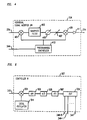
- FIG. 3 depicts a block diagram of an illustrative embodiment of the present invention.
- FIG. 4 is a block diagram of the individual signal modifier of FIG.3.
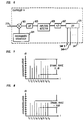
- FIG. 5 is a block diagram of an illustrative controller as shown in FIG. 3.
- FIG.6 is a block diagram of another illustrative controller as shown in FIG.3.
- FIG. 7 depicts the spectral content of an exemplary multicarrier signal.
- FIG.8 depicts the spectral content of the multicarrier signal of FIG.7 after it has been altered according to the present invention.
- FIG.9 is a schematic illustration of a cellular communications system which incorporates the multicarrier signal processor of the present invention.
- FIG. 2 depicts a schematic diagram of a multicarrier signal processor 201 according to the present invention.
- signal processor 201 is described as part of radio receiver front-end 100.
- Radio receiver front-end 100 processes a multicarrier signal comprising a plurality, P, of carrier signals, each of which is individually situated in one of a plurality, P, of distinct frequency bands. Any group of frequency bands can be employed, including those frequency bands having varying widths and non-contiguous frequency bands. The grouping of frequency bands defines a frequency range R.
- FIG. 7 schematically depicts the spectral content of a typical multicarrier signal comprising nine constituent carrier signals, labeled S to S9, each of which is situated in a distinct frequency band.
- the dynamic range of the multicarrier signal is 70 dB (the difference in magnitude between the strongest constituent carrier signal, S3, and the weakest constituent carrier signal, S5).
- the dynamic range of the multicarrier signal in FIG. 7 is reducible by 40 dB, as shown in FIG. 8, by attenuating the power of signals S3 and S6 by 20 dB and boosting the power of signal S5 by 20 dB.
- the dynamic range of the processed signal of FIG. 8 is 30 dB.
- Multicarrier signal processor 201 is typically employed in radio receiver front-end 100 to reduce the dynamic range of a group of P carrier signals of a multicarrier signal.
- the radio receiver front-end generally comprises antenna 101, bandpass filter 105, multicarrier signal processor 201, amplifier 107, mixer 117, and local oscillator 125.
- the radio receiver front-end components are selected from any components or group of components which perform the stated functions, and will not be described in detail. Further description of radio components such as those used in receiver front-end 100 is found in Hickman, Newnes practical RF Handbook, (Newnes, Oxford), c. 1993, the disclosure of which is incorporated by reference herein.
- FIG. 9 depicts cellular communications system 800, partitioned into a number of geographically distinct areas called cells.
- Cell 810 is schematically depicted as a hexagon, however, in practice a cell typically has an irregular shape depending upon the topography of the terrain serviced by the cellular system.
- a cell site 820 which generally includes a base station 822 cooperating with an antenna 824.
- Radio receiver front end 100 is typically incorporated within the base station of cell site 820.
- Wireless terminals 840 communicate with cell site 820 via radio links.
- the expression “wireless terminals” refers to any communications device which receives or transmits an electromagnetic signal through the atmosphere including, but not limited to, mobile telephones, pagers, and personal communicators.
- Cell site 820 optionally communicates with a mobile telecommunications switching office (MTSO) 850, also known as a mobile switching center (MSC).
- the MTSO typically comprises a large switch (e.g., the SESS ® switch available from AT&T Corp.) that routes call to and from wireless terminals in the cellular system and, if necessary, to and from the public switched telephone network (PTSN) via a local office switch 860.
- PTSN public switched telephone network
- Detailed descriptions of cellular communications systems are found in Lee, Mobile Cellular Telecommunications Systems , (McGraw-Hill, N.Y.), c. 1989, Lee, Mobile Communications Design Fundamentals , (Wiley-Interscience), c. 1993, Transmission Systems For Communications , (Bell Telephone Laboratories, NJ), c.
- a multicarrier signal typically comprises a plurality of carrier signals with greatly disparate relative powers, i.e., a signal with a large dynamic range.
- Large dynamic range multicarrier signals negatively impact the performance of numerous system components with limited dynamic ranges such as mixers, amplifiers, and analog-to-digital converters.
- mixer 117 can introduce intermodulation products into the multicarrier signal.
- the intermodulation products combine with the carrier signals, creating a distorted output Multicarrier signal processor 201 mitigates such problems in an exemplary embodiment by analyzing the multicarrier signal to determine the relative power of each of the constituent carrier signals.
- the multicarrier signal processor targets one or more of the constituent carrier signals whose power is beyond a particular range, the range being preset or determined from the multicarrier signal analysis.
- the multicarrier signal processor samples the multicarrier signal and sends at least one sampled multicarrier signal to a signal modifier which changes the phase and/or amplitude of the targeted constituent carrier signal.
- the targeted constituent signal is selected from an individual frequency band or a block or frequency bands, depending upon system needs.
- the modified signal is injected back into the unmodified multicarrier signal in a feedforward architecture. In this manner, the modified signal interacts with the corresponding unmodified constituent carrier signal to reduce the overall dynamic range of the multicarrier signal.
- Multicarrier signal processor 201 reduces the dynamic range of a multicarrier signal in an exemplary embodiment depicted in FIG. 3.
- FIG. 3 depicts a block diagram of the processor 201, which comprises amplifier 390, signal divider 301, signal combiner 303, delay 305, controller 307, and one or more individual signal modifiers, represented by 35N.
- N represents the number of individual signal modifiers in a given embodiment. While there can be any number, N, of individual signal modifiers for a particular application, N is typically less than P.
- the number of individual signal modifiers used in an embodiment is selected based on system considerations, larger numbers of individual signal modifiers generally increase the ability of the multicarrier signal processor to reduce the dynamic range of a multicarrier signal.
- the individual signal modifiers of the present invention can be coupled in series such that a multicarrier signal is sequentially processed by the individual signal modifiers.
- the incoming multicarrier signal is processed by signal divider 301.
- Signal divider 301 receives the multicarrier signal and takes N+2 samples of it, each of which is typically an analog representation of the multicarrier signal.
- Signal divider 301 places one sample of the multicarrier signal onto each of signal paths 311, 315, 371,..., 37N-1 and 37N.
- signal divider 301 is fabricated so that the majority of the power of the multicarrier signal is put onto signal path 311.
- Signal divider 301 is advantageously selected from compound splitters, which generally comprise a combination of 1:2 or 1:3 Wilkinson or hybrid couplers. However, any element which takes an incoming signal and provides plural outputs can be used as signal divider 301.
- Controller 307 receives this multicarrier signal sample and performs several functions. First, the controller analyzes the multicarrier signal to determine the relative power of each of the carrier signals. This may be done on all of the carrier signals simultaneously (e.g., with a fast fourier transform) or serially by scanning for individual carrier signals, one at a time, across the frequency range, R.
- controller 307 is programmed with a threshold.
- the threshold is typically a range selected such that any constituent carrier signal having a power below the threshold lower limit is amplified and any constituent carrier signal having a power above upper limit is attenuated. In this manner, individual carrier signals with power levels that are excessively high or excessively low relative to the other carrier signals are automatically attenuated or automatically amplified.
- This threshold programming may be performed in any known manner.
- the multicarrier signal processor operates with CDMA (code division multiple access) cellular communications systems such that the CDMA equipment is not overwhelmed by signals from analog systems.
- the multicarrier signal comprises both CDMA signals, i.e., spread-spectrum-modulated signals, and higher-powered analog signals, e.g., amplitude-modulated and frequency-modulated signals.
- Controller 307 is preset with a upper threshold which eliminates the substantially higher-powered analog signals.
- the controller instructs the individual signal modifiers to modify the large carrier signal such that the modified signal, when combined with the unmodified multicarrier signal, substantially eliminates the large carrier signal.
- the controller is typically positioned in the CDMA receiver after the bandpass filter, such that the mixer and other dynamic-range-sensitive components are not influenced by the higher-powered analog signals.
- controller 307 After analyzing the incoming multicarrier signal, controller 307 directs individual signal modifiers 351,...35N-1, 35N via pathways 341...34N-1, 34N to isolate and modify a particular constituent carrier signal from the multicarrier signal.
- Each individual signal modifier, 351...35N-1, 35N respectively receives an unmodified multicarrier signal sample from signal divider 301 through paths 371...37N-1, 37N.
- the individual signal modifier isolates its targeted constituent carrier signal or block of carrier signals as directed by controller 307, and modifies it.
- the phase and/or amplitude of the targeted signal is/are changed in preparation for injection back into the unmodified multicarrier signal.
- the amplitude can be decreased by the signal modifier.
- a constituent carrier signal can be created having the same amplitude but 180° out of phase with the corresponding unmodified constituent carrier signal.
- the strength of the constituent carrier signal within the multicarrier signal is reduced upon combination with the corresponding unmodified constituent carrier signal.
- the modified constituent carrier signals are output through signal pathways 381, 38N-1, 38N to signal combiner 303 for combination with the unmodified multicarrier signal.
- Signal combiner 303 receives N+1 signals: one from signal path 311 and one from each of the N individual signal modifiers through pathways 381...38N-1, 38N, and injects the modified isolated signals back into the unmodified multicarrier signal. Typically, combiner 303 creates an output signal that is the vector sum of all N+1 signals.
- Signal combiner 303 is generally selected from any compound splitter, particularly, compound splitters which comprise a combination of 1:2 or 1:3 Wilkinson or hybrid couplers. However, any component which combines signals received from plural pathways can be employed as signal combiner 303.
- the signal sample received from path 311 is a delayed, unmodified multicarrier signal.
- Delay 305 in signal path 311 is preferably set so that the delay through signal path 311 is equal to the delay through signal paths 37N, individual signal modifiers 35N and signal paths 38N.
- Delay elements impart a negative phase slope to the signal upon which they act.
- Delay 305 and the phase shift imparted by each individual signal modifier must be carefully coordinated so that signal combiner 303 effectively performs a vector addition of all of the signals which enter it.
- delay 305 must be set so that the multicarrier signal through signal path 311 and the isolated and modified signal through individual signal modifier 35N arrive at signal combiner 303 at the same time.
- the phase of the output signal from the individual signal modifier is shifted 180° relative to the phase of the unmodified carrier signal, so that the two signals destructively interfere.
- delay 305 is eliminated from signal path 311 and a negative delay element is inserted in signal paths 381, 38N-1, 38N.
- Negative delay elements such as negative group delays, create signals which appear to have propagated a shorter distance than the actual path length by imparting a positive phase slope to the signal.
- the use of negative delay elements in signal paths 381, 38N-1,38N reduces the loss of the unmodified multicarrier signal in signal path 311. Since, in an exemplary embodiment, the majority of the signal strength traverses signal path 311, the overall loss in the multicarrier signal processor is reduced through the use of negative group delays. Exemplary negative group delays are described in U.S. Patent 5,291,156, the disclosure of which is incorporated by reference herein.
- the delay 305 is identical, since the time through the signal paths is the same. However, the phase of the modified carrier signal from the individual signal modifier is adjusted, relative to the phase of the respective unmodified carrier signal, so that the two signals are constructively added.
- FIG. 4 schematically depicts an individual signal modifier 35N for use in the multicarrier signal processor.
- Each individual signal modifier i.e., individual signal modifier 351, 35N-1, and 35N, isolates a targeted carrier signal and modifies its phase and/or amplitude in preparation for being injected back into the unmodified multicarrier signal.
- the individual signal modifier of FIG. 4 comprises mixer 401, bandpass filter 403, phase-shifter 405, amplitude modifier 407, mixer 409, amplifier 411 and programmable synthesizer 413.
- a sample of the multicarrier signal enters mixer 401 from signal path 37N.
- Mixer 401 mixes down the multicarrier signal, so that bandpass filter 403 can isolate the constituent carrier signal targeted for modification by controller 307.
- Programmable synthesizer 413 directs mixer 401 to shift the incoming multicarrier signal such that the targeted carrier signal is positioned at the pass frequency of bandpass filter 403. In this manner, the carrier signal targeted by controller 307 is isolated from the multicarrier signal by bandpass filter 403.
- the carrier signal that is isolated by bandpass filter 403 will be referred to as an isolated carrier signal.
- Bandpass filter 403 is typically a high Q bandpass filter with a passband equal to the frequency bandwidth of the targeted signal or block of signals.
- Phase-shifter 405 selectively changes the phase of the isolated carrier signal by a given number of degrees. For example, by shifting the phase of the signal such that the signal is 180° out of phase with the unmodified carrier signal, the modified carrier signal destructively interferes with the unmodified carrier signal.
- the phase shifter is set such that the modified and unmodified carrier signals are in phase with one another.
- Phase-shifter 405 is provided with either a fixed phase shift, i.e., a phase shift preset for a given number of degrees, or it is provided with a variable capability that is controlled by controller 307.
- phase shifter 407 is programmable such that it adjusts the phase of the signal according to its frequency.
- the isolated carrier signal next enters amplitude modifier 407.
- amplitude modifier 407 is illustratively depicted as an attenuator, the modifier is selected from elements which can amplify, attenuate, or alternatively amplify or attenuate an incoming signal, e.g., amplifiers which are capable of both attenuating and amplifying.
- the amount by which signal modifier 407 either amplifies or attenuates the isolated carrier signal is selected to be either fixed or variable, depending upon system considerations. When the amount is variable, controller 307 directs the amount of attenuation or amplification to be produced by amplitude modifier 407.
- each individual signal modifier can either attenuate or amplify the isolated carrier signal
- signals are only attenuated. Attenuation of signals tends to result in an overall better noise figure for the multicarrier signal processor.
- amplitude modifier 407 is selected to be an attenuator. Typically, the attenuator attenuates the isolated carrier signal by approximately 20 to 30 dB.
- the modified isolated carrier signal enters mixer 409.
- Mixer 409 mixes up the modified isolated carrier signal, as directed by programmable synthesizer 413, to the frequency band in which the carrier signal resided prior to mixing down by mixer 401.
- the modified isolated carrier signal is amplified by amplifier 411, then output to signal combiner 303 via path 38N.
- the modified multicarrier signal is optionally input to another multicarrier signal processor serially connected to the previous multicarrier signal processor. This arrangement provides further reduction in the dynamic range of a multicarrier signal.
- FIG. 5 depicts a block diagram of an illustrative embodiment of controller 307, in which the multicarrier signal is analyzed with a fast fourier transform.
- controller 307 comprises mixer 501, local oscillator 511, bandpass filter 503, analog-to- digital converter 505, fast-fourier transform analyzer 507 and digital signal processor 509.
- the multicarrier signal received from signal divider 301 via signal path 315 is mixed down by mixer 501 to an intermediate frequency, in well-known fashion.
- Mixer 501 is controlled by local oscillator 511.
- the mixed-down signal is input to bandpass filter 503.
- Bandpass filter 503 is preferably a high Q filter with a passband width equal to the frequency range, R, of interest.
- the filtered multicarrier signal is passed to analog-to-digital converter 505.
- Analog-to-digital converter 505 converts the analog output of bandpass filter 503 to a digital format for analysis by fast-fourier transformer 507.
- Fast-fourier transformer 507 takes the multicarrier signal and produces its spectral content, as illustrated in FIGS. 7 and 8.
- Digital signal processor 509 takes the output of fast-fourier transformer 507, and analyzes the dynamic range, determining which carrier signals should be targeted for attenuation (or amplification) and, optionally, the amount of attenuation or amplification. In one embodiment, digital signal processor 509 also determines the amount of phase shift for each targeted carrier signal or block of carrier signals. Additionally, digital signal processor 509 sends a signal to each individual signal modifier indicating which targeted carrier signal the individual signal modifier is to isolate for attenuation or amplification.
- FIG. 6 depicts a block diagram of an alternate embodiment of controller 307, which analyzes the multicarrier signal by scanning across it for individual carrier signals in sequential fashion.
- controller 307 comprises mixer 601, programmable synthesizer 611, bandpass filter 603, amplitude detector 605, analog-to-digital converter 607 and digital signal processor 609.
- Mixer 601 mixes down the multicarrier signal from signal path 315 to an intermediate frequency, as directed by programmable synthesizer 611.
- the mixed-down signal is sent to bandpass filter 603.
- Bandpass filter 603 is typically a high Q filter with a passband width equal to the frequency range of interest.
- Amplitude detector 605 takes the filtered multicarrier signal and determines the average power of the individual scanned signal, in well-known fashion.
- Analog-to-digital converter 607 converts the analog output of amplitude detector 605 to a digital format for use by digital signal processor 609.
- Digital signal processor 609 determines the amplitude of the carrier signal being analyzed, and directs programmable synthesizer 611 to serially tune to a different carrier signal until all of the carrier signals in the multicarrier signal have been analyzed. Additionally, digital signal processor 609 determines which carrier signals should be targeted for attenuation or amplification.
- the digital signal processor directs each individual signal modifier by sending a signal indicating which carrier signal that individual signal modifier is to isolate and attenuate or amplify and, optionally, the amount of carrier signal amplification or attenuation.
- multicarrier signal processors of the present invention Numerous advantages are realized through the use of the multicarrier signal processors of the present invention.
- conventional systems typically employ interdigital filters in the position of filter 105 which are expensive to produce and bulky to install at cell sites. Such filters are needed in conjunction with conventional receivers to prevent interference between the bands of the A and B carriers within a cellular market.
- the present invention permits the use of smaller, less expensive filters in the receiver since the multicarrier signal processor essentially creates the effect of an ideal filter.
- Exemplary filters for use with the present invention are barium titanate duplex filters. Barium titanate duplex filters are described in U.S. Patent No. 3,938,064, the disclosure of which is incorporated herein by reference.
- the present invention advantageously reduces the dynamic range of a multicarrier signal without eliminating carrier signals and the information which they carry. Because individual carrier signals are merely attenuated or amplified, only the dynamic range is reduced without excluding the information-carrying frequency bands of the multicarrier signal.
Landscapes
- Engineering & Computer Science (AREA)
- Computer Networks & Wireless Communication (AREA)
- Signal Processing (AREA)
- Digital Transmission Methods That Use Modulated Carrier Waves (AREA)
- Reduction Or Emphasis Of Bandwidth Of Signals (AREA)
- Measurement And Recording Of Electrical Phenomena And Electrical Characteristics Of The Living Body (AREA)
Applications Claiming Priority (2)
| Application Number | Priority Date | Filing Date | Title |
|---|---|---|---|
| US08/315,382 US5694395A (en) | 1994-09-30 | 1994-09-30 | Method and apparatus for processing multicarrier signals |
| US315382 | 1994-09-30 |
Publications (3)
| Publication Number | Publication Date |
|---|---|
| EP0704983A2 true EP0704983A2 (de) | 1996-04-03 |
| EP0704983A3 EP0704983A3 (de) | 1999-07-14 |
| EP0704983B1 EP0704983B1 (de) | 2002-03-06 |
Family
ID=23224148
Family Applications (1)
| Application Number | Title | Priority Date | Filing Date |
|---|---|---|---|
| EP95306626A Expired - Lifetime EP0704983B1 (de) | 1994-09-30 | 1995-09-20 | Verfahren und Schaltung zur Behandlung von Mehrträgersignalen |
Country Status (6)
| Country | Link |
|---|---|
| US (2) | US5694395A (de) |
| EP (1) | EP0704983B1 (de) |
| JP (1) | JP3294082B2 (de) |
| KR (1) | KR100580797B1 (de) |
| CA (1) | CA2157310C (de) |
| DE (1) | DE69525702T2 (de) |
Cited By (4)
| Publication number | Priority date | Publication date | Assignee | Title |
|---|---|---|---|---|
| WO2000039936A1 (en) * | 1998-12-24 | 2000-07-06 | Nokia Networks Oy | A device and method for reducing the amplitude of signals |
| WO2001099316A1 (en) * | 2000-06-16 | 2001-12-27 | Fujitsu Limited | Multi-carrier amplifier |
| WO2003036892A1 (de) * | 2001-09-28 | 2003-05-01 | Siemens Aktiengesellschaft | Vorrichtung und verfahren zur unterdrückung von periodischen störsignalen |
| DE102009008269A1 (de) * | 2009-02-10 | 2010-08-12 | Bayerische Motoren Werke Aktiengesellschaft | Verfahren zum Rundfunkempfang |
Families Citing this family (54)
| Publication number | Priority date | Publication date | Assignee | Title |
|---|---|---|---|---|
| JP3672056B2 (ja) * | 1995-08-18 | 2005-07-13 | 松下電器産業株式会社 | タイミング信号発生回路 |
| SE9801241L (sv) * | 1997-04-09 | 1998-10-10 | Daewoo Telecom Ltd | PC-CDMA-multibärfrekvenssystem |
| US5898362A (en) * | 1997-06-02 | 1999-04-27 | Motorola, Inc. | System for transmitting and receiving polarized CDMA signals and method of operation thereof |
| US6195537B1 (en) * | 1997-09-25 | 2001-02-27 | Lucent Technologies, Inc. | Method and apparatus for strong signal suppression in multi-carrier signals |
| US6400697B1 (en) * | 1998-01-15 | 2002-06-04 | At&T Corp. | Method and apparatus for sector based resource allocation in a broadhand wireless communications system |
| US6396819B1 (en) | 1998-03-21 | 2002-05-28 | Richard D. Fleeter | Low-cost satellite communication system |
| US6704317B1 (en) | 1998-05-27 | 2004-03-09 | 3Com Corporation | Multi-carrier LAN modem server |
| US6507585B1 (en) | 1998-05-27 | 2003-01-14 | 3Com Corporation | Multi-carrier LAN adapter device using frequency domain equalizer |
| US6891887B1 (en) | 1998-05-27 | 2005-05-10 | 3Com Corporation | Multi-carrier LAN adapter device using interpolative equalizer |
| US6377683B1 (en) | 1998-05-29 | 2002-04-23 | 3Com Corporation | Low complexity frequency domain echo canceller for DMT transceivers |
| US6603811B1 (en) | 1998-05-29 | 2003-08-05 | 3Com Corporation | Low complexity frequency domain equalizer having fast re-lock |
| US6445747B1 (en) | 1998-07-14 | 2002-09-03 | At&T Corporation | Method and apparatus to reduce peak to average power ratio in multi-carrier modulation |
| US6590906B1 (en) * | 1998-08-24 | 2003-07-08 | Matsushita Electric Industrial Co., Ltd. | Multi-carrier transmitter circuit and communication equipment |
| US6324407B1 (en) * | 1999-02-26 | 2001-11-27 | Motorola, Inc. | Method and apparatus for signal transmission within a wireless communication system |
| US6208207B1 (en) | 1999-05-05 | 2001-03-27 | Simon Fraser University | Adaptive linearizer for RF power amplifiers |
| KR100680075B1 (ko) * | 1999-09-13 | 2007-02-09 | 유티스타콤코리아 유한회사 | 코드 분할 다중 접속방식 이동통신 기지국 시스템의 무선주파수 수신장치에서 에프에이간 전력레벨 제어장치 |
| US6961369B1 (en) | 1999-11-09 | 2005-11-01 | Aware, Inc. | System and method for scrambling the phase of the carriers in a multicarrier communications system |
| US7227884B2 (en) | 2000-02-28 | 2007-06-05 | Aeroastro, Inc. | Spread-spectrum receiver with progressive fourier transform |
| KR100377197B1 (ko) | 2000-12-26 | 2003-03-26 | 한국전자통신연구원 | 다중 캐리어 무선통신 수신 시스템의 캐리어 분리 장치 및그 방법 |
| US6734731B2 (en) * | 2001-06-28 | 2004-05-11 | Simon Fraser University | Self-calibrated power amplifier linearizers |
| US7015751B2 (en) | 2001-06-28 | 2006-03-21 | Simon Fraser University | Decorrelated power amplifier linearizers |
| US6683495B2 (en) | 2001-06-28 | 2004-01-27 | Simon Fraser University | Reduced architecture for multibranch feedforward power amplifier linearizers |
| AU2002328010A1 (en) * | 2002-08-28 | 2004-04-23 | Agency For Science, Technology And Research | Method for dynamic range reduction in a wideband receiver |
| US8159982B2 (en) * | 2003-01-21 | 2012-04-17 | Nokia Corporation | Method, system and network entity for providing digital broadband transmission |
| JP4157506B2 (ja) * | 2003-07-29 | 2008-10-01 | 株式会社東芝 | 無線受信装置及び無線受信方法 |
| US9026070B2 (en) | 2003-12-18 | 2015-05-05 | Qualcomm Incorporated | Low-power wireless diversity receiver with multiple receive paths |
| US8019303B2 (en) * | 2004-09-28 | 2011-09-13 | Intel Corporation | Multi-antenna multicarrier receiver and methods for adaptively adjusting a receive data rate based on channel utilization |
| FR2890808A1 (fr) * | 2005-09-13 | 2007-03-16 | France Telecom | Caracterisation de spectre pour equipements de communication |
| US9450665B2 (en) | 2005-10-19 | 2016-09-20 | Qualcomm Incorporated | Diversity receiver for wireless communication |
| WO2007136415A2 (en) | 2005-12-30 | 2007-11-29 | Comtech Mobile Datacom Corporation | Mobile satellite communications |
| US7904047B2 (en) * | 2007-10-31 | 2011-03-08 | Broadcom Corporation | Radio frequency filtering technique with auto calibrated stop-band rejection |
| US8385871B2 (en) * | 2008-12-01 | 2013-02-26 | Rockstar Consortium Us Lp | Frequency agile filter using a digital filter and bandstop filtering |
| US8548107B1 (en) | 2009-01-26 | 2013-10-01 | Comtech Mobile Datacom Corporation | Advanced multi-user detector |
| US9106364B1 (en) | 2009-01-26 | 2015-08-11 | Comtech Mobile Datacom Corporation | Signal processing of a high capacity waveform |
| US8675711B1 (en) * | 2009-09-25 | 2014-03-18 | Comtech Mobile Datacom Corporation | System and methods for dynamic spread spectrum usage |
| WO2012000761A1 (en) * | 2010-06-28 | 2012-01-05 | Alcatel Lucent | Multicarrier receiver in a wireless telecommunication network |
| US9178669B2 (en) | 2011-05-17 | 2015-11-03 | Qualcomm Incorporated | Non-adjacent carrier aggregation architecture |
| US9252827B2 (en) | 2011-06-27 | 2016-02-02 | Qualcomm Incorporated | Signal splitting carrier aggregation receiver architecture |
| US9154179B2 (en) | 2011-06-29 | 2015-10-06 | Qualcomm Incorporated | Receiver with bypass mode for improved sensitivity |
| US20130016634A1 (en) * | 2011-07-12 | 2013-01-17 | Telefonaktiebolaget L M Ericsson (Publ) | Electronic duplexer |
| US12081243B2 (en) | 2011-08-16 | 2024-09-03 | Qualcomm Incorporated | Low noise amplifiers with combined outputs |
| US8774334B2 (en) | 2011-11-09 | 2014-07-08 | Qualcomm Incorporated | Dynamic receiver switching |
| US9172402B2 (en) | 2012-03-02 | 2015-10-27 | Qualcomm Incorporated | Multiple-input and multiple-output carrier aggregation receiver reuse architecture |
| US9362958B2 (en) | 2012-03-02 | 2016-06-07 | Qualcomm Incorporated | Single chip signal splitting carrier aggregation receiver architecture |
| US9118439B2 (en) * | 2012-04-06 | 2015-08-25 | Qualcomm Incorporated | Receiver for imbalanced carriers |
| US9154356B2 (en) | 2012-05-25 | 2015-10-06 | Qualcomm Incorporated | Low noise amplifiers for carrier aggregation |
| US9867194B2 (en) | 2012-06-12 | 2018-01-09 | Qualcomm Incorporated | Dynamic UE scheduling with shared antenna and carrier aggregation |
| US9300420B2 (en) | 2012-09-11 | 2016-03-29 | Qualcomm Incorporated | Carrier aggregation receiver architecture |
| US9543903B2 (en) | 2012-10-22 | 2017-01-10 | Qualcomm Incorporated | Amplifiers with noise splitting |
| US20140226973A1 (en) * | 2013-02-11 | 2014-08-14 | Peter H. Wolff | System and Method for Isolating RF Signals for Transmission Over Multiple Channels on a Single Transmission Path |
| US8995591B2 (en) | 2013-03-14 | 2015-03-31 | Qualcomm, Incorporated | Reusing a single-chip carrier aggregation receiver to support non-cellular diversity |
| US20150181615A1 (en) * | 2013-12-23 | 2015-06-25 | Adc Telecommunications, Inc. | Systems and methods for capacity management for a distributed antenna system |
| US9240815B1 (en) * | 2014-03-25 | 2016-01-19 | Rockwell Collins, Inc. | Reconfigurable filter |
| US10177722B2 (en) | 2016-01-12 | 2019-01-08 | Qualcomm Incorporated | Carrier aggregation low-noise amplifier with tunable integrated power splitter |
Citations (1)
| Publication number | Priority date | Publication date | Assignee | Title |
|---|---|---|---|---|
| US3938064A (en) | 1973-09-04 | 1976-02-10 | Bell Telephone Laboratories, Incorporated | Devices using low loss dielectric material |
Family Cites Families (15)
| Publication number | Priority date | Publication date | Assignee | Title |
|---|---|---|---|---|
| US4583049A (en) * | 1984-06-15 | 1986-04-15 | Trw Inc. | Feed-forward circuit |
| US4811422A (en) * | 1986-12-22 | 1989-03-07 | Kahn Leonard R | Reduction of undesired harmonic components |
| US4953156A (en) * | 1988-09-08 | 1990-08-28 | Gte Laboratories, Incorporated | Wideband subcarrier multiplexed optical communication system operating over more than one octave |
| US4879519A (en) * | 1988-10-31 | 1989-11-07 | American Telephone And Telegraph Company, At&T Bell Labs | Predistortion compensated linear amplifier |
| US4885551A (en) * | 1988-10-31 | 1989-12-05 | American Telephone And Telegraph Company At&T Bell Laboratories | Feed forward linear amplifier |
| US5012490A (en) * | 1989-12-26 | 1991-04-30 | At&T Bell Laboratories | Varying bandwidth digital signal detector |
| US5222106A (en) * | 1990-02-07 | 1993-06-22 | Kokusai Denshin Denwa Kabushiki Kaisha | Interference detection and reduction |
| US5168508A (en) * | 1990-08-07 | 1992-12-01 | Clarion Co., Ltd. | Spread spectrum receiver |
| JPH05191178A (ja) * | 1992-01-16 | 1993-07-30 | Japan Radio Co Ltd | 電力増幅装置 |
| US5252934A (en) * | 1992-08-25 | 1993-10-12 | At&T Bell Laboratories | Microwave delay assembly |
| US5300894A (en) * | 1992-10-20 | 1994-04-05 | At&T Bell Laboratories | Circuitry for minimizing peak power in an amplifier carrying a plurality of signals of differing frequencies |
| US5291156A (en) * | 1993-02-10 | 1994-03-01 | At&T Bell Laboratories | Method and apparatus for imparting positive phase slope to a narrowband signal |
| US5304945A (en) * | 1993-04-19 | 1994-04-19 | At&T Bell Laboratories | Low-distortion feed-forward amplifier |
| US5489875A (en) * | 1994-09-21 | 1996-02-06 | Simon Fraser University | Adaptive feedforward linearizer for RF power amplifiers |
| US5570350A (en) * | 1994-09-30 | 1996-10-29 | Lucent Technologies Inc. | CDMA cellular communications with multicarrier signal processing |
-
1994
- 1994-09-30 US US08/315,382 patent/US5694395A/en not_active Expired - Lifetime
-
1995
- 1995-08-31 CA CA002157310A patent/CA2157310C/en not_active Expired - Lifetime
- 1995-09-20 DE DE69525702T patent/DE69525702T2/de not_active Expired - Lifetime
- 1995-09-20 EP EP95306626A patent/EP0704983B1/de not_active Expired - Lifetime
- 1995-09-28 JP JP27366195A patent/JP3294082B2/ja not_active Expired - Lifetime
- 1995-09-29 KR KR1019950032611A patent/KR100580797B1/ko not_active Expired - Lifetime
- 1995-12-29 US US08/581,418 patent/US5694396A/en not_active Expired - Lifetime
Patent Citations (1)
| Publication number | Priority date | Publication date | Assignee | Title |
|---|---|---|---|---|
| US3938064A (en) | 1973-09-04 | 1976-02-10 | Bell Telephone Laboratories, Incorporated | Devices using low loss dielectric material |
Cited By (7)
| Publication number | Priority date | Publication date | Assignee | Title |
|---|---|---|---|---|
| WO2000039936A1 (en) * | 1998-12-24 | 2000-07-06 | Nokia Networks Oy | A device and method for reducing the amplitude of signals |
| US7035360B2 (en) | 1998-12-24 | 2006-04-25 | Nokia Corporation | Device and method for reducing the amplitude of signals |
| CN100438352C (zh) * | 1998-12-24 | 2008-11-26 | 诺基亚公司 | 降低信号幅度的一种设备和方法 |
| WO2001099316A1 (en) * | 2000-06-16 | 2001-12-27 | Fujitsu Limited | Multi-carrier amplifier |
| WO2003036892A1 (de) * | 2001-09-28 | 2003-05-01 | Siemens Aktiengesellschaft | Vorrichtung und verfahren zur unterdrückung von periodischen störsignalen |
| DE102009008269A1 (de) * | 2009-02-10 | 2010-08-12 | Bayerische Motoren Werke Aktiengesellschaft | Verfahren zum Rundfunkempfang |
| DE102009008269B4 (de) | 2009-02-10 | 2023-06-29 | Bayerische Motoren Werke Aktiengesellschaft | Verfahren zum Rundfunkempfang |
Also Published As
| Publication number | Publication date |
|---|---|
| JPH08125576A (ja) | 1996-05-17 |
| US5694396A (en) | 1997-12-02 |
| CA2157310C (en) | 2000-06-20 |
| DE69525702T2 (de) | 2002-10-17 |
| KR100580797B1 (ko) | 2006-08-23 |
| JP3294082B2 (ja) | 2002-06-17 |
| CA2157310A1 (en) | 1996-03-31 |
| KR960012805A (ko) | 1996-04-20 |
| DE69525702D1 (de) | 2002-04-11 |
| EP0704983B1 (de) | 2002-03-06 |
| EP0704983A3 (de) | 1999-07-14 |
| US5694395A (en) | 1997-12-02 |
Similar Documents
| Publication | Publication Date | Title |
|---|---|---|
| US5694395A (en) | Method and apparatus for processing multicarrier signals | |
| US5570350A (en) | CDMA cellular communications with multicarrier signal processing | |
| US5625871A (en) | Cellular communications system with multicarrier signal processing | |
| RU2414064C2 (ru) | Технологии повторителя для системы с множеством входов и множеством выходов с использованием формирователей диаграммы направленности | |
| US6567648B1 (en) | System combining radio frequency transmitter and receiver using circulator and method for canceling transmission signal thereof | |
| EP0704982B1 (de) | Rundfunk Empfänger zur Verarbeitung eines Mehrträgersignals mit grossem dynamischen Bereich | |
| US6738609B1 (en) | Receiver and method of receiving | |
| US7035360B2 (en) | Device and method for reducing the amplitude of signals | |
| EP0569504A4 (de) | Intermodulationsausgleichung in einem empfangssystem. | |
| JPH09312587A (ja) | 無線通信装置 | |
| EP1710920A1 (de) | Empfang von modulierten Funksignalen | |
| US20030206576A1 (en) | Apparatus for improving intermodulation distortion characteristics in a CDMA mobile terminal | |
| US6393011B1 (en) | Receiving circuit of mobile communication terminal having feed forward linearizer | |
| US6545487B1 (en) | System and method for producing an amplified signal with reduced distortion | |
| US6608523B1 (en) | System and method for producing a pilot signal in a distortion reduction system | |
| US6785524B2 (en) | Device and method for controlling the amplitude of signals | |
| Williamson et al. | Performance Analysis of Adaptive Wideband Duplexer | |
| CN1295385A (zh) | 电磁信号的发射/接收装置 | |
| KR200199765Y1 (ko) | 이득조정기능을 갖는 무선중계기용 채널선택장치와, 이를이용한 채널선택형 무선중계기 | |
| KR100226360B1 (ko) | 인접 송수신 안테나간의 무선주파수 간섭제거 시스템 | |
| KR100652001B1 (ko) | 이동 단말기의 대역 필터 및 그 제어 방법 | |
| KR20020041950A (ko) | 피드포워드 방식 선형 전력증폭기의 불요파 대역 신호제거 장치 | |
| HK1008709A (en) | A radio receiver for processing a multi-carrier signal with a large dynamic range |
Legal Events
| Date | Code | Title | Description |
|---|---|---|---|
| PUAI | Public reference made under article 153(3) epc to a published international application that has entered the european phase |
Free format text: ORIGINAL CODE: 0009012 |
|
| AK | Designated contracting states |
Kind code of ref document: A2 Designated state(s): DE GB |
|
| PUAL | Search report despatched |
Free format text: ORIGINAL CODE: 0009013 |
|
| AK | Designated contracting states |
Kind code of ref document: A3 Designated state(s): DE GB |
|
| RIC1 | Information provided on ipc code assigned before grant |
Free format text: 6H 04B 1/10 A, 6H 03F 1/32 B |
|
| 17P | Request for examination filed |
Effective date: 19991210 |
|
| 17Q | First examination report despatched |
Effective date: 20000524 |
|
| GRAG | Despatch of communication of intention to grant |
Free format text: ORIGINAL CODE: EPIDOS AGRA |
|
| GRAG | Despatch of communication of intention to grant |
Free format text: ORIGINAL CODE: EPIDOS AGRA |
|
| GRAH | Despatch of communication of intention to grant a patent |
Free format text: ORIGINAL CODE: EPIDOS IGRA |
|
| GRAH | Despatch of communication of intention to grant a patent |
Free format text: ORIGINAL CODE: EPIDOS IGRA |
|
| REG | Reference to a national code |
Ref country code: GB Ref legal event code: IF02 |
|
| GRAA | (expected) grant |
Free format text: ORIGINAL CODE: 0009210 |
|
| AK | Designated contracting states |
Kind code of ref document: B1 Designated state(s): DE GB |
|
| REF | Corresponds to: |
Ref document number: 69525702 Country of ref document: DE Date of ref document: 20020411 |
|
| PLBE | No opposition filed within time limit |
Free format text: ORIGINAL CODE: 0009261 |
|
| STAA | Information on the status of an ep patent application or granted ep patent |
Free format text: STATUS: NO OPPOSITION FILED WITHIN TIME LIMIT |
|
| 26N | No opposition filed |
Effective date: 20021209 |
|
| PGFP | Annual fee paid to national office [announced via postgrant information from national office to epo] |
Ref country code: DE Payment date: 20140922 Year of fee payment: 20 |
|
| PGFP | Annual fee paid to national office [announced via postgrant information from national office to epo] |
Ref country code: GB Payment date: 20140919 Year of fee payment: 20 |
|
| REG | Reference to a national code |
Ref country code: DE Ref legal event code: R071 Ref document number: 69525702 Country of ref document: DE |
|
| REG | Reference to a national code |
Ref country code: GB Ref legal event code: PE20 Expiry date: 20150919 |
|
| PG25 | Lapsed in a contracting state [announced via postgrant information from national office to epo] |
Ref country code: GB Free format text: LAPSE BECAUSE OF EXPIRATION OF PROTECTION Effective date: 20150919 |