EP0705047A2 - Méthode et système pour l'appel d'un terminal mobile dans un système de communication mobile - Google Patents
Méthode et système pour l'appel d'un terminal mobile dans un système de communication mobile Download PDFInfo
- Publication number
- EP0705047A2 EP0705047A2 EP95306643A EP95306643A EP0705047A2 EP 0705047 A2 EP0705047 A2 EP 0705047A2 EP 95306643 A EP95306643 A EP 95306643A EP 95306643 A EP95306643 A EP 95306643A EP 0705047 A2 EP0705047 A2 EP 0705047A2
- Authority
- EP
- European Patent Office
- Prior art keywords
- base station
- identifier
- mobile terminal
- location registration
- mobile
- Prior art date
- Legal status (The legal status is an assumption and is not a legal conclusion. Google has not performed a legal analysis and makes no representation as to the accuracy of the status listed.)
- Granted
Links
- 238000010295 mobile communication Methods 0.000 title claims description 45
- 238000000034 method Methods 0.000 title claims description 42
- 238000012546 transfer Methods 0.000 claims abstract description 16
- 238000005266 casting Methods 0.000 claims 1
- 230000008569 process Effects 0.000 description 22
- 238000010276 construction Methods 0.000 description 17
- 101150080339 BTS1 gene Proteins 0.000 description 16
- 238000012790 confirmation Methods 0.000 description 10
- 230000000875 corresponding effect Effects 0.000 description 9
- 238000010586 diagram Methods 0.000 description 9
- 230000004044 response Effects 0.000 description 8
- 230000001276 controlling effect Effects 0.000 description 5
- 101100232406 Arabidopsis thaliana IBS1 gene Proteins 0.000 description 3
- 101100398918 Arabidopsis thaliana IPMS2 gene Proteins 0.000 description 3
- 101100041621 Arabidopsis thaliana SAC6 gene Proteins 0.000 description 3
- 101100018850 Luffa aegyptiaca IMS1 gene Proteins 0.000 description 3
- 238000004891 communication Methods 0.000 description 3
- 238000005516 engineering process Methods 0.000 description 3
- 230000006870 function Effects 0.000 description 3
- 238000005259 measurement Methods 0.000 description 3
- 101100107120 Arabidopsis thaliana ZEP gene Proteins 0.000 description 2
- 230000001413 cellular effect Effects 0.000 description 2
- 230000002596 correlated effect Effects 0.000 description 2
- 238000007796 conventional method Methods 0.000 description 1
- 230000003247 decreasing effect Effects 0.000 description 1
- 230000009467 reduction Effects 0.000 description 1
- 238000013519 translation Methods 0.000 description 1
Images





Classifications
-
- H—ELECTRICITY
- H04—ELECTRIC COMMUNICATION TECHNIQUE
- H04W—WIRELESS COMMUNICATION NETWORKS
- H04W68/00—User notification, e.g. alerting and paging, for incoming communication, change of service or the like
Definitions
- the present invention relates to a method for calling a mobile terminal in a mobile communication system and a device using the calling method and, more particularly, to a method and a device thereof for calling a mobile terminal locating in a location registration area comprising a plurality of radio zones.
- a conventional mobile communication system such as a cellular phone or a portable phone has employed a small zone system which covers its whole service areas by a plurality of radio zones.
- the radio zone refers to a range where a radio channel communication is executed between each base station and a mobile terminal (a radio terminal or a portable phone) equipped in an automobile and so on.
- Each radio zone has one base station placed therein.
- a plurality of mobile terminals are allowed to move in or out of any radio zones.
- the mobile communication system employing the small zone system requires each mobile terminal to register the radio zone in which it currently locates so as to inform the base station of its current location for a call reception.
- a plurality of location registration areas are set by dividing the whole service area into groups of some adjacent radio zones.
- the mobile terminal registers its location at every movement to the location registration area.
- the information on the location registration area to which the mobile terminal belongs is reported to a mobile exchange office and stored.
- the mobile exchange office receives a call for a mobile terminal, the mobile exchange office sends a call signal to all base stations within a location registration area to which the mobile terminal belongs. Responding to the call signal, all base stations begin to execute simultaneous calling to the addressed mobile terminal.
- the number of radio zones that belong to a location registration area is increased when the number of location registration signals has increased. While, the number of radio zones that belong to a location registration area is decreased when the number of call signals has increased.
- Fig. 10 is a block diagram of a method for controlling mobile communication channel disclosed in a Japanese Patent Laid Open No. 289898 (1991).
- a function of a mobile exchange office 1A of Fig. 10 is divided into a mobile communication gateway exchange office, a location control means and a mobile communication exchange office.
- the mobile communication system divides a specific field into a plurality of radio zones 51 to 59, and disposes base stations BTS1 to BTS9 to cover the respective radio zones.
- a mobile exchange office 1A for controlling those base stations BTS1 to BTS9 is provided in the mobile communication system.
- the mobile exchange office 1A is connected to a public channel network 3 and to a mobile exchange office 2A for controlling other base stations (not shown).
- a mobile exchange office 2A has the same function as that of the mobile exchange office 1A.
- a mobile terminal 4 in the form of an automotive cellular phone or a portable phone is allowed to communicate with another subscriber connected to the public channel network 3 or the mobile exchange office 2A via a base station (if the mobile terminal 4 locates in a radio zone 52, its base station is BTS2.) placed corresponding to the radio zone (the radio zone 52) in which it locates and the mobile exchange office 1A.
- the radio zones 51 to 59 in Fig. 10 are grouped into location registration areas A1 to A3. That is, the radio zones 51 to 53 belong to the location registration area A1.
- the radio zones 54 to 56 likewise belong to the location registration area A2.
- the radio zones 57 to 59 belong to the location registration area A3.
- the mobile terminal 4 When the mobile terminal 4 moves from one location where location registration is covering the respective base stations BTS1 to BTS9 to its adjacent location registration area, it sends a location registration signal to the mobile exchange office 1A via the base station where the location is registered.
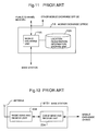
- Fig. 11 is a block diagram of an example of a construction of the mobile exchange office 1A shown in Fig. 10.
- Fig. 12 is a block diagram of an example of a construction of the base station BTS1 shown in Fig. 10.
- the mobile exchange office 2A has the same construction as that shown in Fig. 11 and is connected to base stations (not shown).
- the base stations BTS2 to BTS9 have the same construction as that of the base station BTS1 shown in Fig. 12.
- mobile terminal identifiers IBTS1, IBTS2, ... and IBTSN are preliminary allocated to each mobile terminal.
- the base station BTS1 to BTS9 have their own registration identifiers IBTS1 to IBTS9 allocated thereto, respectively.
- the mobile exchange office 1A comprises a location registration information storing unit 12A which stores location registration information representing correlation among the mobile terminal identifiers of the mobile terminal 4, location registration area to which the mobile terminal 4 belongs and registration identifier of the base station belonging to the location registration area.
- the mobile exchange office 1A further comprises a mobile exchange unit 11A connected to the base stations BTS1 to BTS9 as well as the public channel network and other mobile exchange office 2A for calling the addressed mobile terminal 4 by referring the content of the received call from the public channel network or the mobile exchange office, and updating the content of the location registration storing unit 12A upon receiving the location registration signal from the mobile terminal 4 via the base station.
- the base station BTS1 shown in Fig. 12 comprises a cable send and receive unit 23A connected to the mobile exchange office 1A for receiving a signal including the call signal sent from the mobile exchange office 1A and sending the signal output from the radio send and receive unit to the mobile exchange office 1A.
- the BTS1 further comprises a radio send and receive unit 22A for sending an output of the cable send and receive unit 23A via a radio channel and outputting a signal sent from the mobile terminal 4 to the cable send and receive unit 23A.
- Fig. 13 is a flowchart showing a calling process executed in the mobile communication system shown in Fig. 10.
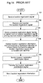
- Fig. 14 is a flowchart showing a location registration process executed in the mobile communication system shown in Fig. 10.
- a mobile exchange unit 11A reads out a location registration area code representing the registered identifier contained in the received call by referring the content of the location registration information storing unit 12A (step 92). It further reads out registration identifiers allocated to all the base stations contained in the location registration area (step 93).
- the mobile exchange office 11A sends a call signal to all the base stations (BTS1 to BTS3) allocated to the registration identifiers which have been read out (step 94). That is, simultaneous read out is executed.
- the base stations (BTS1 to BTS3 in Fig. 10) which receive the above call signal send a call signal to the mobile terminal 4 in return (step 95).
- the mobile terminal 4 stores the location registration area where it currently locates. When moving to the adjacent location registration area, the mobile terminal 4 sends a location registration signal containing a mobile terminal identifier which has been preliminary allocated thereto (step 101).
- the base stations BTS1, BTS2 and BTS 4 receive the location registration signal, they add their registration identifiers to the received location registration signal and transfer them as location registration signals to the mobile exchange office 1A (step 102).
- the mobile exchange office 1A compares the level of the respective location registration signals, and select the location registration system with the highest level (step 103). Assuming that the base station which has sent the location registration signal with the highest level is, for example, the BTS2 which has sent the location registration signal with the highest level compared with those from the BTS1 and BTS4, it is determined that the mobile terminal locates in the location registration area containing the base station BTS2.
- the location registration information representing the correlation between the location registration area A1 containing the mobile terminal identifier allocated to the addressed mobile terminal and registration identifiers IBTS1, IBTS2 and IBTS3 of the base stations BTS1, BTS2 and BTS3 in the radio zone covered by the location registration area A1 is updated and stored in the location registration information storing unit 12A (step 104).
- the mobile exchange office 1A generates a location registration confirmation signal of the mobile terminal 4 and send it to the base station BTS2 (step 105).
- the base station BTS2 transfers this location registration confirmation signal to the mobile terminal 4 (step 106).
- the mobile terminal 4 receives the location registration confirmation signal, the mobile terminal 4 stores its contents, i.e., the location registration area contained in the location registration confirmation signal (step 107).
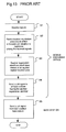
- Fig. 15 is a flowchart of a channel establishment process in the mobile communication systems of both a prior art and the present invention.
- the mobile terminal 4 upon receiving a call signal, the mobile terminal 4 outputs a response signal in a predetermined manner (step 81).
- a plurality of base stations for example, BTS2 and BTS3, receive the response signal, they add their own registration identifiers to the response signal, respectively, as response signals, then transfer them to the mobile exchange office 1A (step 82).
- the mobile exchange office 1A compares levels of a plurality of received response signals and selects a response signal at the highest level sent from, for example, the BTS2 (step 83).
- the mobile exchange office 1A establishes a channel connecting to the base station which has sent the selected response signal for communication. (step 85).
- the mobile exchange office 1A stops setting the channel (step 86).
- the mobile exchange office if a call for a mobile terminal is received by a mobile exchange office of the mobile communication system, the mobile exchange office sends call signals to all the base stations contained in the location registration area including the radio zone where the addressed mobile terminal currently locates.
- the invention provides a method for calling a mobile terminal in a mobile communication system with a plurality of radio zones each of the radio zones has a base station, the method comprising steps of: making a base station store identifiers of predetermined base stations except for own identifier; making a mobile exchange office controlling the plurality of base stations store an identifier of a mobile terminal and an identifier of a base station where these two identifiers are corresponding each other; making the mobile exchange office search an identifier of a mobile terminal from among stored identifiers when the mobile exchange office has received a call signal for the mobile terminal, making the mobile exchange office search an identifier of a base station corresponding to the searched identifier from among the stored identifiers; making the mobile exchange office send the call signal for the mobile terminal to a base station of which identifier has been searched; making a base station discriminate a sender of the call signal when the base station has received the call signal; making a base station call the mobile terminal in a radio zone belonging the base station
- the invention provides a mobile communication system having a plurality of base stations provided in respective radio zones and a mobile exchange office for controlling the plurality of base stations, and calling a mobile terminal via the base station when the mobile exchange office has received a call signal for the mobile terminal
- the mobile communication system having: the mobile exchange office comprising: first storing means for storing an identifier of each mobile terminal and an identifier of a base station, wherein these two identifiers are corresponding each other; and means for searching an identifier of a base station corresponding to an identifier of a mobile terminal from the first storing means when having received a call signal for the mobile terminal, and sending the call signal for the mobile terminal to a base station of which identifier has been searched; and the base stations, each of the base stations comprising: second storing means for storing identifiers of the base stations except for own identifier; means for discriminating a sender of a call signal; and means for transferring the call signal to a base station of which identifier is stored in the
- the mobile exchange office stores the location registration information in which a mobile terminal identifier is correlated with a registration identifier of a base station in a radio zone holding the mobile terminal having the above-identified mobile terminal identifier.
- the base station when responding to the receipt of a call by the mobile exchange office, only one base station corresponding to the mobile terminal identifier of the addressed mobile terminal is read out from location registration information within the mobile exchange office. Then a call signal is sent only to the corresponding base station. Receiving the call signal, the base station transfers the signal to another base station which has been preliminary stored for simultaneous calling to the mobile terminals.
- the load accompanied by the calling process of the mobile exchange office is reduced and its process is partially executed by the base station. Therefore even if a plurality of calls for different mobile terminals are received, calling processes may be executed to mobile terminals more quickly.
- Fig. 1 is a construction view of a mobile communication system of the present embodiment.
- Fig. 2 is a block diagram showing a construction of a mobile exchange office in the mobile communication system of the present embodiment.
- Fig. 3 is an explanatory view showing a content of location registration information stored in a location registration area information storing unit.
- Fig. 4 is a block diagram of a construction of a base station of the present embodiment.
- Fig. 5 is an explanatory view showing a content of location registration area information stored in the location registration area information storing unit.
- the mobile communication system of the embodiment has the same construction as that of the above-mentioned conventional mobile communication system except that mobile exchange offices 1 and 2 are employed instead of 1A and 2A and base stations BS1 to BS9 are employed instead of BTS1 to BTS9.
- the base stations BS1 to BS9 have registration identifiers IBS1 to IBS9 allocated thereto, respectively.
- the mobile terminal 4 has a mobile terminal identifier IMS1 allocated thereto.
- the different mobile terminal identifiers have been preliminary allocated to the "n" sets of the mobile terminals 4, respectively.
- the mobile exchange office 1 comprises a mobile exchange unit 11 connected to a public channel network 3, another mobile exchange office (for example, a mobile exchange office 2) and the base stations BS1 to BS9, and a location registration information storing unit 12 connected to the mobile exchange unit 11 for storing the location registration information.
- the location registration information storing unit 12 stores the location registration information representing correlation between a mobile terminal identifier of the mobile terminal and an identifier of a base station at every mobile terminal which locates and registers in location registration areas A1 to A3 under the control of the mobile exchange office 1.
- Fig. 3 shows a content of the location registration information stored in the location registration information storing unit 12 when the mobile terminal 4 having a mobile terminal identifier IMS1 registers its location in the base station BS2 having a registration identifier of IBS2. Updating of the location registration information is described later.
- the mobile exchange office 2 has the same construction as that of the mobile exchange office 1.
- a reference numeral 22 is a radio send and receive unit for transmitting/receiving signals to/from the mobile terminal 4.
- a reference numeral 21 is an antenna connected to the radio send and receive unit 22 for communicating with the mobile terminal 4.
- a reference numeral 23 is a cable send and receive unit for outputting a signal received by an antenna 21 to the mobile exchange office 1.
- the cable send and receive unit 23 receives a signal from the mobile exchange office 1 and other base stations (e.g., base station BS2), the cable send and receive unit 23 outputs a signal to the radio send and receive unit 22 or a call signal transfer unit 25 (described later) depending on the content of the received signal.
- a reference numeral 24 is a location registration area information storing unit for storing the location registration area information representing registration identifiers of other base stations to which the call signal sent from the mobile exchange office 1 should be transferred.
- the location registration area information is stored within the location registration area information storing unit 24 in such a manner that each registration identifier of the base station to which a call signal received from the mobile exchange office 1 should be transferred is marked off with a comma.
- Fig. 5 shows that the call signal is transferred from the base station BS1 to base stations BS1 and BS3.
- a reference numeral 25 is a call signal transfer unit for outputting a signal by determining a sender of the call signal, i.e., whether the call signal received from the cable send and receive unit 23 has been sent from the mobile exchange office or other base station, (e.g., base station BS3).
- a reference numeral 26 is an adjacent base station information update unit for outputting an identifier of each base station extracted from path information sent from the mobile terminal to an adjacent base station information storing unit.
- the path information is well-known for being transmitted when the mobile terminal executes location registration, which has been disclosed in the US Patent No. 5,305,466.
- a reference numeral 27 is an adjacent base station information storing unit for calculating appearance frequency of the identifier of the radio relay station output from the adjacent base station information update unit 26, and stores the frequency information as shown in Fig. 6.
- a reference numeral 28 is a call traffic measurement unit for measuring traffic of the call signal among those received by the cable send and receive unit 23.
- a reference numeral 29 is a location registration area information update unit for updating the stored content of the location registration area information storing unit 24.
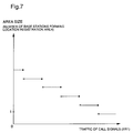
- the location registration area information update unit 29 determines the number of the identifiers of the base station, "n", based on the measurement results of the call traffic measurement unit 28 and a correlation as shown in Fig. 7. Among information stored in the adjacent base station information storing unit 27, "n" identifiers are selected sequentially in order of the greatest appearance frequency. Then the stored content of the location registration area information storing unit 24 is updated into the selected identifiers.
- This embodiment presents a method for measuring the call signal traffic as a method for updating the location registration area.
- Other methods for example, for using traffic of the location registration signal are available. An explanation of the above method is omitted because detailed description has been disclosed in the U.S. Patent No. 5,305,466.
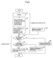
- Fig. 8 is a flowchart showing a calling process of th mobile communication system of the present embodiment.
- Fig. 9 is a flowchart showing a location registration process of the present embodiment.
- a mobile exchange office 1 calls a mobile terminal 4 upon receiving the call addressed thereto from outside.
- the mobile terminal 4 is assumed to present in a location registration area including the radio zone of the base station BS2.
- the mobile exchange unit 11 receives the call and reads out a registration identifier allocated to the base station corresponding to the registration identifier of the addressed mobile terminal 4 which has been contained in the received signal by detecting the stored content of the location registration information storing unit 12 (step 62).
- the identifier of the base station corresponding to the mobile terminal identifier IMS1 of the mobile terminal 4 is IBS2.
- the mobile exchange unit 11 sends a call signal to the base station BS2 having the registration identifier IBS2 which has been read out (step 63). At this time the mobile exchange unit 11 adds information identifying a sender as the mobile exchange office 1 to the call signal.
- the cable send and receive unit 23 of the base station BS2 determines whether or not it is addressed to its own station (step 64). If the call signal is addressed to its own station, the call signal is output to the call signal transfer unit 25.
- the call signal transfer unit 25 determines whether an input call signal has been sent from the mobile exchange office 1 or other base station (step 65).
- registration identifiers IBS1 and IBS3 are read out from other base stations by detecting stored content of the location registration area information storing unit 24. Then a call signal is sent to the base stations BS1 and BS3 having registration identifiers IBS1 and IBS3, respectively via the cable send and receive unit 23 (step 67).
- the call signal transfer unit 25 adds information identifying a sender as the base station BS2 to the call signal.
- the call signal is output to the radio send and receive unit 22 of its own station (step 66).
- the call signal is output to the radio send and receive unit 22 of its own station (step 66).
- the mobile terminal 4 Moving out of a predetermined location registration area to its adjacent location registration area, the mobile terminal 4 outputs a location registration signal in the same manner as a conventional mobile communication system (step 71).
- the location registration signal accommodates registration identifiers of the base station (e.g., BS2) where the mobile terminal 4 locates (e.g.,BS2) and other base stations (e.g., BS1, BS3 and BS5) which have received the location registration signal as additional information.
- the location registration signal is, then, transferred to the mobile exchange office 1 (step 72).
- the mobile exchange unit 11 compares each level of the location registration signal and selects the one at the highest level (step 73).
- the mobile exchange unit 11 determines that the mobile terminal 4 locates in the radio zone of the base station which has sent the selected location registration signal at the highest level and further stores the location registration information by updating into the one representing the correlation between the registration identifier of the determined base station and the mobile terminal identifier of the mobile terminal 4 (step 74).
- the mobile exchange unit 11 generates a location registration signal addressed to the mobile terminal 4 and outputs a location registration confirmation signal to the base station which has sent the location registration signal at the highest level (step 75).
- the base station transfers the received location registration confirmation signal to the mobile terminal 4 (step 76).
- the mobile terminal 4 identifies as to which location registration area it is currently registered by referring the location registration area information contained in the location registration confirmation signal. The information is further stored in the mobile terminal 4 (step 77).
- This embodiment employs 1 set of the mobile terminal, 3 location registration areas and 3 radio zones contained in the location registration area. However, it is obvious that they may be set to desired numbers.
Landscapes
- Engineering & Computer Science (AREA)
- Computer Networks & Wireless Communication (AREA)
- Signal Processing (AREA)
- Mobile Radio Communication Systems (AREA)
Applications Claiming Priority (3)
| Application Number | Priority Date | Filing Date | Title |
|---|---|---|---|
| JP23274794 | 1994-09-28 | ||
| JP232747/94 | 1994-09-28 | ||
| JP6232747A JP2590754B2 (ja) | 1994-09-28 | 1994-09-28 | 移動体通信システムの呼出し方法とその装置 |
Publications (3)
| Publication Number | Publication Date |
|---|---|
| EP0705047A2 true EP0705047A2 (fr) | 1996-04-03 |
| EP0705047A3 EP0705047A3 (fr) | 1998-01-07 |
| EP0705047B1 EP0705047B1 (fr) | 2005-11-23 |
Family
ID=16944130
Family Applications (1)
| Application Number | Title | Priority Date | Filing Date |
|---|---|---|---|
| EP95306643A Expired - Lifetime EP0705047B1 (fr) | 1994-09-28 | 1995-09-20 | Méthode et système pour l'appel d'un terminal mobile dans un système de communication mobile |
Country Status (4)
| Country | Link |
|---|---|
| US (1) | US5812949A (fr) |
| EP (1) | EP0705047B1 (fr) |
| JP (1) | JP2590754B2 (fr) |
| DE (1) | DE69534626T2 (fr) |
Cited By (2)
| Publication number | Priority date | Publication date | Assignee | Title |
|---|---|---|---|---|
| US6518993B2 (en) | 2000-03-10 | 2003-02-11 | Nokia Mobile Phones Limited | Mobile imaging |
| AU776221B2 (en) * | 2000-03-31 | 2004-09-02 | Nec Platforms, Ltd. | Mobile communication system and mobile communication method |
Families Citing this family (20)
| Publication number | Priority date | Publication date | Assignee | Title |
|---|---|---|---|---|
| KR100441473B1 (ko) * | 1996-06-27 | 2004-11-03 | 가부시키가이샤 엔.티.티.도코모 | 무선호출방식 |
| JP4124499B2 (ja) * | 1996-11-14 | 2008-07-23 | 富士通株式会社 | 移動体通信システムにおいてソフトハンドオフを実施する方法及びそのための移動体通信システム並びに無線基地局 |
| US6073016A (en) * | 1997-01-02 | 2000-06-06 | Telxon Corporation | Mobile device ID allocation system and method |
| US6792267B1 (en) * | 1998-05-29 | 2004-09-14 | Ericsson Inc. | Systems and methods for uplinking downsampled radiotelephone signals from cellular radiotelephone base stations to a cellular radio exchange |
| DE19824141A1 (de) * | 1998-05-29 | 1999-12-02 | Siemens Ag | Übergabeverfahren (Roaming) für mobile Endeinrichtungen |
| JP3717805B2 (ja) * | 2001-06-07 | 2005-11-16 | 三洋電機株式会社 | 移動通信端末機 |
| US8041815B2 (en) * | 2001-09-21 | 2011-10-18 | Microsoft Corporation | Systems and methods for managing network connectivity for mobile users |
| JP2003264860A (ja) * | 2002-01-07 | 2003-09-19 | Fujitsu Ltd | 移動機の使用者の行動を反映する情報の提供方法とそれを実現する移動交換局、情報提供装置および移動機 |
| US7472135B2 (en) * | 2002-10-18 | 2008-12-30 | Nokia Corporation | Method and system for recalling details regarding past events |
| JP4136710B2 (ja) * | 2003-02-21 | 2008-08-20 | 富士通株式会社 | 移動通信網装置、基地局、及び移動局 |
| EP2034751B1 (fr) * | 2006-06-06 | 2017-08-23 | Panasonic Intellectual Property Management Co., Ltd. | Système de communication radio, terminal radio, station de base et procédé de recherche de station de base |
| US8855830B2 (en) | 2009-08-21 | 2014-10-07 | Allure Energy, Inc. | Energy management system and method |
| US8498749B2 (en) | 2009-08-21 | 2013-07-30 | Allure Energy, Inc. | Method for zone based energy management system with scalable map interface |
| US9838255B2 (en) | 2009-08-21 | 2017-12-05 | Samsung Electronics Co., Ltd. | Mobile demand response energy management system with proximity control |
| US9209652B2 (en) | 2009-08-21 | 2015-12-08 | Allure Energy, Inc. | Mobile device with scalable map interface for zone based energy management |
| US20130054863A1 (en) | 2011-08-30 | 2013-02-28 | Allure Energy, Inc. | Resource Manager, System And Method For Communicating Resource Management Information For Smart Energy And Media Resources |
| US9716530B2 (en) | 2013-01-07 | 2017-07-25 | Samsung Electronics Co., Ltd. | Home automation using near field communication |
| US10063499B2 (en) | 2013-03-07 | 2018-08-28 | Samsung Electronics Co., Ltd. | Non-cloud based communication platform for an environment control system |
| CA2936076C (fr) | 2014-01-06 | 2022-07-26 | Allure Energy, Inc. | Systeme, dispositif et appareil de coordination d'environnements utilisant des dispositifs de reseau et des informations sensorielles distantes |
| CN106464551A (zh) | 2014-01-06 | 2017-02-22 | 魅力能源公司 | 一种使用网络装置和基于遥感的信息来协调环境的系统、装置和设备 |
Citations (2)
| Publication number | Priority date | Publication date | Assignee | Title |
|---|---|---|---|---|
| JPH03289898A (ja) | 1990-04-06 | 1991-12-19 | Nippon Telegr & Teleph Corp <Ntt> | 移動通信回線制御方式 |
| US5305466A (en) | 1990-02-20 | 1994-04-19 | Nec Corporation | Location registration and paging procedure for mobile communication |
Family Cites Families (1)
| Publication number | Priority date | Publication date | Assignee | Title |
|---|---|---|---|---|
| EP0546572B1 (fr) * | 1991-12-12 | 1999-04-07 | Nec Corporation | Système de communications mobile avec un poste de radio central pour faire appeler des usagers mobiles par la voie des stations de base |
-
1994
- 1994-09-28 JP JP6232747A patent/JP2590754B2/ja not_active Expired - Fee Related
-
1995
- 1995-09-20 DE DE69534626T patent/DE69534626T2/de not_active Expired - Lifetime
- 1995-09-20 EP EP95306643A patent/EP0705047B1/fr not_active Expired - Lifetime
- 1995-09-22 US US08/532,889 patent/US5812949A/en not_active Expired - Fee Related
Patent Citations (2)
| Publication number | Priority date | Publication date | Assignee | Title |
|---|---|---|---|---|
| US5305466A (en) | 1990-02-20 | 1994-04-19 | Nec Corporation | Location registration and paging procedure for mobile communication |
| JPH03289898A (ja) | 1990-04-06 | 1991-12-19 | Nippon Telegr & Teleph Corp <Ntt> | 移動通信回線制御方式 |
Cited By (2)
| Publication number | Priority date | Publication date | Assignee | Title |
|---|---|---|---|---|
| US6518993B2 (en) | 2000-03-10 | 2003-02-11 | Nokia Mobile Phones Limited | Mobile imaging |
| AU776221B2 (en) * | 2000-03-31 | 2004-09-02 | Nec Platforms, Ltd. | Mobile communication system and mobile communication method |
Also Published As
| Publication number | Publication date |
|---|---|
| DE69534626D1 (de) | 2005-12-29 |
| JP2590754B2 (ja) | 1997-03-12 |
| EP0705047A3 (fr) | 1998-01-07 |
| DE69534626T2 (de) | 2006-05-18 |
| US5812949A (en) | 1998-09-22 |
| EP0705047B1 (fr) | 2005-11-23 |
| JPH0898232A (ja) | 1996-04-12 |
Similar Documents
| Publication | Publication Date | Title |
|---|---|---|
| US5812949A (en) | Method for calling a mobile terminal in a mobile communication system and a device thereof | |
| US5384824A (en) | Method for carrying out a location updating from a mobile cellular radiophone system to another cellular radiophone system | |
| JP2628950B2 (ja) | 携帯電話システムにおける位置登録方法 | |
| EP0660991B1 (fr) | Remise a jour de la localisation dans un reseau radio cellulaire | |
| EP0165929B1 (fr) | Controle de systemes de commutation de telecommunications | |
| US5960356A (en) | Paging a mobile station within a public land mobile network (PLMN) | |
| US5873047A (en) | Method for setting up perch channels in mobile communication by cellular system | |
| JP3127957B2 (ja) | 移動通信システムにおける位置登録方法 | |
| EP0475865A2 (fr) | Système d'enregistrement de localisation pour communication mobile | |
| JPH0856378A (ja) | 移動体パケット通信方式 | |
| US5442684A (en) | Method and arrangement of locating cordless units in wide area cordless telephone system | |
| JP2800455B2 (ja) | 移動通信システムの位置登録方式および呼出し方式 | |
| US6108519A (en) | Mobile communications system | |
| US7933551B2 (en) | Mobile communication system and mobile communication method | |
| JP2000512822A (ja) | セルラー方式無線システムにおける位置管理及びページング方法 | |
| AU668793B2 (en) | Private branch radio extension terminating system | |
| US5640443A (en) | Movable telephone communication system | |
| AU7948498A (en) | Method and system for paging a mobile station | |
| EP1118233B1 (fr) | Procede permettant de determiner une zone locale pour un terminal d'abonne, systeme radio associe et element de reseau d'abonne | |
| JP2947263B2 (ja) | 移動通信システムおよび無線基地局ならびに移動機 | |
| JPH0927985A (ja) | 移動体通信システム | |
| JP3487258B2 (ja) | 移動通信システム及び呼び出し制御方法 | |
| GB2362299A (en) | Paging a mobile station | |
| HK1007372B (en) | Method for carrying out a location updating from a mobile cellular radiophone system to another cellular radiophone system | |
| MXPA97007296A (es) | Sistema y metodo para localizar una terminal movildentro del area de servicio de un sistema detelecomunicacion celular |
Legal Events
| Date | Code | Title | Description |
|---|---|---|---|
| PUAI | Public reference made under article 153(3) epc to a published international application that has entered the european phase |
Free format text: ORIGINAL CODE: 0009012 |
|
| AK | Designated contracting states |
Kind code of ref document: A2 Designated state(s): DE FR GB |
|
| PUAL | Search report despatched |
Free format text: ORIGINAL CODE: 0009013 |
|
| AK | Designated contracting states |
Kind code of ref document: A3 Designated state(s): DE FR GB |
|
| 17P | Request for examination filed |
Effective date: 19971217 |
|
| 17Q | First examination report despatched |
Effective date: 20040812 |
|
| GRAP | Despatch of communication of intention to grant a patent |
Free format text: ORIGINAL CODE: EPIDOSNIGR1 |
|
| GRAS | Grant fee paid |
Free format text: ORIGINAL CODE: EPIDOSNIGR3 |
|
| GRAA | (expected) grant |
Free format text: ORIGINAL CODE: 0009210 |
|
| AK | Designated contracting states |
Kind code of ref document: B1 Designated state(s): DE FR GB |
|
| REG | Reference to a national code |
Ref country code: GB Ref legal event code: FG4D |
|
| REF | Corresponds to: |
Ref document number: 69534626 Country of ref document: DE Date of ref document: 20051229 Kind code of ref document: P |
|
| ET | Fr: translation filed | ||
| PLBE | No opposition filed within time limit |
Free format text: ORIGINAL CODE: 0009261 |
|
| STAA | Information on the status of an ep patent application or granted ep patent |
Free format text: STATUS: NO OPPOSITION FILED WITHIN TIME LIMIT |
|
| 26N | No opposition filed |
Effective date: 20060824 |
|
| PGFP | Annual fee paid to national office [announced via postgrant information from national office to epo] |
Ref country code: GB Payment date: 20090916 Year of fee payment: 15 |
|
| PGFP | Annual fee paid to national office [announced via postgrant information from national office to epo] |
Ref country code: DE Payment date: 20090917 Year of fee payment: 15 |
|
| PGFP | Annual fee paid to national office [announced via postgrant information from national office to epo] |
Ref country code: FR Payment date: 20091012 Year of fee payment: 15 |
|
| GBPC | Gb: european patent ceased through non-payment of renewal fee |
Effective date: 20100920 |
|
| REG | Reference to a national code |
Ref country code: FR Ref legal event code: ST Effective date: 20110531 |
|
| REG | Reference to a national code |
Ref country code: DE Ref legal event code: R119 Ref document number: 69534626 Country of ref document: DE Effective date: 20110401 |
|
| PG25 | Lapsed in a contracting state [announced via postgrant information from national office to epo] |
Ref country code: FR Free format text: LAPSE BECAUSE OF NON-PAYMENT OF DUE FEES Effective date: 20100930 Ref country code: DE Free format text: LAPSE BECAUSE OF NON-PAYMENT OF DUE FEES Effective date: 20110401 |
|
| PG25 | Lapsed in a contracting state [announced via postgrant information from national office to epo] |
Ref country code: GB Free format text: LAPSE BECAUSE OF NON-PAYMENT OF DUE FEES Effective date: 20100920 |