EP0705212B1 - Pneumatische fördereinrichtung mit dämpferlöser steuerung und verfahren zum fördern von gesammelten artikeln - Google Patents
Pneumatische fördereinrichtung mit dämpferlöser steuerung und verfahren zum fördern von gesammelten artikeln Download PDFInfo
- Publication number
- EP0705212B1 EP0705212B1 EP94920199A EP94920199A EP0705212B1 EP 0705212 B1 EP0705212 B1 EP 0705212B1 EP 94920199 A EP94920199 A EP 94920199A EP 94920199 A EP94920199 A EP 94920199A EP 0705212 B1 EP0705212 B1 EP 0705212B1
- Authority
- EP
- European Patent Office
- Prior art keywords
- air
- louvers
- conveyor
- downstream
- conveyor surface
- Prior art date
- Legal status (The legal status is an assumption and is not a legal conclusion. Google has not performed a legal analysis and makes no representation as to the accuracy of the status listed.)
- Expired - Lifetime
Links
Images

Classifications
-
- B—PERFORMING OPERATIONS; TRANSPORTING
- B65—CONVEYING; PACKING; STORING; HANDLING THIN OR FILAMENTARY MATERIAL
- B65G—TRANSPORT OR STORAGE DEVICES, e.g. CONVEYORS FOR LOADING OR TIPPING, SHOP CONVEYOR SYSTEMS OR PNEUMATIC TUBE CONVEYORS
- B65G51/00—Conveying articles through pipes or tubes by fluid flow or pressure; Conveying articles over a flat surface, e.g. the base of a trough, by jets located in the surface
- B65G51/02—Directly conveying the articles, e.g. slips, sheets, stockings, containers or workpieces, by flowing gases
- B65G51/03—Directly conveying the articles, e.g. slips, sheets, stockings, containers or workpieces, by flowing gases over a flat surface or in troughs
-
- B—PERFORMING OPERATIONS; TRANSPORTING
- B65—CONVEYING; PACKING; STORING; HANDLING THIN OR FILAMENTARY MATERIAL
- B65G—TRANSPORT OR STORAGE DEVICES, e.g. CONVEYORS FOR LOADING OR TIPPING, SHOP CONVEYOR SYSTEMS OR PNEUMATIC TUBE CONVEYORS
- B65G2201/00—Indexing codes relating to handling devices, e.g. conveyors, characterised by the type of product or load being conveyed or handled
- B65G2201/02—Articles
- B65G2201/0235—Containers
- B65G2201/0244—Bottles
Definitions
- This invention relates to an air conveyor apparatus for use with generally cylindrical lightweight articles and more particularly to a damperless conveyor which controls the conveying speed of the articles whether en masse or in a sparse or individual flow of articles.
- air conveyors have become popular for conveying lightweight articles, such as cylindrical lightweight beverage containers, both during the manufacturing of the containers and during the filling operation.
- Such conveyors have enjoyed considerable success because they allow the conveying of the containers at a much higher speed than was possible with mechanical conveyors.
- These air conveyors have used, in various forms, air jets and louvers for moving the containers along the conveying surface.
- the angle at which air is introduced to the conveying surface has included jets or louvers directing the air parallel to the direction of movement as well as various angles transversely to the direction of movement. In general, it has been the intent of these devices to use the blowing force of the air to move the containers in the desired direction.
- Barker U.S. Patent No. 3,105,720, shows the use of louvers at opposite ends of cylindrical containers for moving them vertically from one conveyor to another.
- Futer, U.S. Patent No. 3,180,688, discloses a mass conveyor which utilizes a series of louvers and vertical jets.
- the vertical jets suspend the articles above the conveyor while the louvers provide a downstream propelling force for moving the articles in the downstream direction.
- U.S. Patent No. 3,385,490 discloses a device for conveying web or sheet material along a conveyor in which louvers are provided which are angled inwardly from the outboard edges of the conveyor toward the center.
- An exhaust grid is provided at the center of the device for evacuation of air.
- This device is intended to center a sheet of material and convey it downstream due to the downstream force component of the air passing through the louvers.
- the inboard component of the air from the louvers is intended to be equal on both sides and therefore center the sheet material over the conveyor.
- Hassan et al. U.S. Patent No. 4,165,132, discloses an air conveyor for conveying semiconductor wafers wherein air jets are provided at an inboard angle from the side edges of the conveyor for suspending and centering the wafers over the conveyor. These jets also create a downstream force component which moves the wafer along the conveyor in the downstream direction.
- the pressure is set too low in an attempt to slow the speed of the article, the article will not be levitated sufficiently above the deck surface and cannot be conveyed. Conversely, if the pressure is set too high, in order to convey the article at the higher speed, the article will be levitated too high above the deck and may wobble, so that it does not flow smoothly down the air conveyor and may tip over, creating a jam along the conveyor.
- an air conveyor comprising: a coverless conveyor surface extending from an upstream location to a downstream location for moving articles en masse from said upstream location to said downstream location, said surface having first and second opposite side edges and an underside; a common plenum connectable to a source of air under pressure and attached to said underside of said conveyor for supplying air under pressure; a first set of louvers extending across said conveyor surface and through said conveyor surface at an incline to said conveyor surface so that the air passing therethrough has a downstream force vector of a first magnitude; and a second set of louvers selectively spaced from said first set of louvers and extending across said conveyor surface and through said conveyor surface at an incline to said conveyor surface so that the air passing therethrough has an upstream force vector of a second magnitude which is less than said first magnitude creating a force differential favouring the downstream direction to cause the articles to move in a downstream direction from said upstream location to said downstream location.
- a method of conveying articles en masse at a controlled speed along a coverless air conveyor from an upstream location to a downstream location wherein the air conveyor includes a mass conveyor surface extending from the upstream location to the downstream location and an air plenum for supplying air to the conveyor surface said method comprising: directing air along the conveyor surface from the plenum at an upward incline thereto by passing the air through a first set of laterally extending louvers so that the air has a downstream vector of a first larger magnitude, directing air along the conveyor surface from the plenum at an upward incline thereto by passing the air through a second set of laterally extending louvers selectively spaced from said first set of louvers, and wherein the first and second sets of louvers are positionable so that the air has an upstream vector of a second lesser magnitude resulting in a differential force vector in the downstream direction.
- isometric means and refers to opposing air volumes creating opposed force vectors along the upper surface of the deck of the conveyor.
- a first set of louvers extends through the conveyor surface in a downstream direction at an incline to the conveying surface so that the air passing through the louvers has a downstream force vector of a first magnitude.
- a second set of louvers extends through the conveyor surface in an upstream direction at an incline to the conveying surface so that the air passing through the louvers has a upstream force vector of a second magnitude which is less than the first magnitude thereby creating a vector force differential in the downstream direction to cause movement of the articles in the downstream direction.
- louvers along each edge of the conveying surface may be angled in the inboard direction to cause a cross flow of air which creates an air barrier through which a single or sparse flow of articles must move, thereby limiting the speed of the single or sparse articles.
- the inboard cross flow of air also creates a low pressure drafting effect at the trailing edge of the sparse articles to assist in maintaining them in an upright position.
- a first set of longitudinally extending louvers is arranged in alternating longitudinal rows with a second set of longitudinally extending louvers wherein an outboard row of louvers on each side of the deck or conveying surface is always part of the first set. This assures that there is at least one more row of louvers in the downstream direction than in the upstream direction.
- multiple rows of longitudinally extending louvers in the downstream direction can be provided with longitudinally extending upstream louvers interspaced therebetween.
- at least the first outboard row of downstream longitudinally extending louvers can be angled in the inboard direction to provide air flowing transversely of the direction of movement of the containers to create an air barrier to impede movement of single or sparse flow of articles.
- the longitudinally extending louvers will all be substantially covered so that the only flow of air is against the bottom of the containers to move them en masse in the desired downstream direction due to the net downstream force vector.
- the rows of longitudinally extending louvers have been defined as longitudinally traversing the conveyor surface, however; the rows of louvers can also be defined as traversing laterally across the conveyor surface. That is, depending upon the various embodiments disclosed herein, the first and second sets of louvers can be defined as arrangements of either laterally or longitudinally extending rows that traverse the conveyor surface.
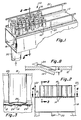
- a conveyor 10 which has a conveying surface in the form of a deck 12 with louvers 14 therein for conveying containers 16 from an upstream location to a downstream location as will be more fully discussed below.
- a plenum 18 is attached to the bottom side of deck 12 and is supplied by air from a common air supply, such as a blower (not shown) through an inlet 20.
- Open rails 22 are provided along the outboard edges of deck 12 to hold the containers on the conveying surface.
- the air passes through the louvers and, due to the Coanda Effect, travels along the surface of the deck in the direction of arrows 24.
- the flow of air emitted from the louvers creates a low pressure area thereby holding the bottom 26 of container 16 closely adjacent the deck 12.
- the isometric deck design of this invention is based upon opposing air volumes at identical velocities.
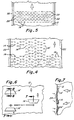
- a preferred longitudinal louver design across the conveyor deck width is shown in Figure 4.
- the first two longitudinal rows of louvers 14 from each outboard edge direct flow in the downstream flow direction.
- the next inboard row of longitudinal louvers 13 is in the opposing upstream direction followed by the next two inboard rows of longitudinal louvers 14 in the downstream flow direction and then repeating the pattern.
- the following will exemplify the pattern: 16 longitudinal rows are in the downstream flow direction and seven longitudinal rows are in the upstream opposing upstream flow direction. This gives 228% more louvers in the downstream flow direction.
- a first set of lateral rows 15 laterally extend or traverse across the conveyor surface wherein an interspersed and alternating second set of lateral rows 17 extend or traverse laterally across the conveyor surface.
- the first set of louvers 15, as shown in Figure 5 direct flow in the upstream direction and the second set of louvers 17 direct flow in the downstream direction.
- the same type of calculations as described above with respect to Figure 4 can be made. That is, providing more louvers in the downstream direction and then adjusting the area of the louvers in the upstream direction is one manner in which desired speed can be achieved.
- the louver in the deck is of a trapezoid design, as shown in Figures 6 and 7.
- the cross-sectional area of the louver may be varied within very close parameters which also controls the volume of air dispersed through the louver.
- H the vector force differential can be precisely controlled.
- Ambient air is also drawn in through side rail 22, as shown by arrows 27 in Figure 9, which assists in moving the containers in the downstream direction.
- the isometric deck design may be configured to decelerate random containers prior to entering a turn and accelerate them out of the turn at any point within the turn and then resume the maximum set speed. If the air conveyor were to interface with a mechanical conveyor supplying the containers, the isometeric deck design may be configured to accelerate the containers away from the mechanical conveyor so as to disperse the density at which they are being supplied and then a gradual deceleration to the maximum set speed.
- the above is a deck design which will propel a single container along any distance at a maximum speed of approximately 61 meters per minute (200 FPM) without a top cover on the air conveyor.
- This same deck design is also capable of conveying any container density shown at the FPM shown with minimum static pressure within the plenum.
- the container-to-container impact noise is extremely low. The containers are conveyed so gently that no container damage was detected.
- FIG. 10 A still further embodiment is shown in Figure 10 wherein three diagonally extending rows of angled louvers 30 are provided along each outboard edge of deck 12. This creates cross flow air which acts as a barrier through which a single or sparse flow of containers must move. This cross flow air also has a drafting effect on the back or trailing side of the single or sparse flow of containers creating a low pressure area which pulls this trailing edge toward deck 12.
- a mass of containers say 100% density
- the cross flow air is restricted and the louvers act only on the bottom of containers to move the mass of containers in the downstream direction due to the net downstream force vector, previously described.
- louvers 30 The greater the volume of air discharged through the angled louvers 30, the more effective they will be in slowing the speed of single or sparse containers, yet at the same time, the angled louvers 30 will be effectively increasing the speed of densely grouped containers that pass over louvers 30.
- an object such as a 340g (12oz) aluminum container, requires 1.27cm (0.5 inches) of static pressure to provide an optimum volume of air beneath it to levitate it about 0.127mm (0.005 inches) above the conveyor deck.
- the air velocity through louvers having an opening of 0.052cm 2 (0.00808 square inches) is at a speed of 863m per minute (2,832 feet per minute, FPM).
- the inboard angle A of louvers 30 is sixty (60) degrees, the FVV is thirty percent (30%) of 863m per minute (2.832 FPM) or 259m per minute (850 FPM), a desired speed for conveying a dense pack of containers.
- Controlling the speed of a container in an air conveyor is an absolute prerequisite in today's market because of the ever increasing lighter containers.
- the lighter the container the more it is susceptible to damage from container-to-container impact or container-to-guide rail impact at turns in the conveyor which are downstream of a straightaway conveyor section.
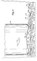
- the angle of incline of the louvers from the deck surface is approximately 25° to 30°, as seen in Figures 8 and 11, creating a laminar flow of air across the deck surface, because of the Coanda Effect, which air travels at a high velocity relative to the surrounding ambient air.
- the angle of incline range set forth above is exemplary only. The actual angle may be somewhat greater or lesser. This greater air speed produces a decrease in pressure in accordance with the Bernoulli Principle.
- the Coanda Effect is the tendency of a jet of gas when discharged adjacent a surface to follow that surface even though it curves away from the jet axis. This causes entrainment of ambient air surrounding the wall thereby reducing the pressure above it.
- This low pressure area 32 acts to stabilize and pull the container toward the deck, as illustrated by arrows 34 while the air escaping beneath the diameter of the container, through the very slight 0.076mm (0.003 inch) to 0.127mm (0.005 inch) vertical space between the deck and the bottom of the container, also creates a low pressure area further enhancing the drafting effect to draw the container toward the deck surface.
- the shallow angle of incline of the louvers to the deck surface maintains the majority of the air flow at or very near the base of the container which is well below the center of gravity of the container.
- a damperless, controlled speed, coverless air conveyor has been provided in which damage of fragile containers, such as lightweight aluminum beverage containers, is greatly minimized.
- the number and/or size of the louvers can be varied to provide a very precise differential downstream air flow to upstream air flow to very precisely control the speed of a mass of containers moving from an upstream location to a downstream location along the conveyor.
- air barriers can be created by the cross flowing air to impede the movement of single or sparsely bunched containers so that they do not reach terminal velocity but rather flow at approximately the same rate as a mass of containers.
- the number or size of the louvers along the deck precise increases and decreases in the velocity of the containers can be obtained as required for making turns or entering or leaving a mechanical conveying device.
- the net air volume in the downstream direction is substantially the same at an incremental position along the deck surface when the ratio of downstream louver area to upstream louver area is constant.
- the deck can have an upward incline from the upstream location to the downstream location of 7.9mm (5/16") per linear foot without requiring additional static pressure for moving the article.
- This isometric conveyor of this invention is usable with aluminum, steel, and plastic containers, as well as cylinders which are open at both ends and flat STYROFOAM® plates.
Landscapes
- Physics & Mathematics (AREA)
- Engineering & Computer Science (AREA)
- Fluid Mechanics (AREA)
- Mechanical Engineering (AREA)
- Attitude Control For Articles On Conveyors (AREA)
- Intermediate Stations On Conveyors (AREA)
Claims (21)
- Pneumatischer Förderer (10), der umfaßt:eine abdeckungslose Förderfläche (12), die sich von einer stromauf gelegenen Position zu einer stromab gelegenen Position erstreckt und dazu dient, Gegenstände (16) in einer Masse von der stromauf gelegenen Position zu der stromab gelegenen Position zu bewegen, wobei die Fläche einen ersten und einen zweiten seitlichen Rand, die einander gegenüberliegen, und eine Unterseite hat; eine gemeinsame Luftkammer, die mit einer Quelle von Druckluft verbunden werden kann und an der Unterseite des Förderers angebracht ist, um Druckluft zuzuführen;eine erste Gruppe von Luftschlitzen (14), die sich quer zu der Förderfläche (12) und durch die Förderfläche (12) hindurch zu der Förderfläche (12) geneigt erstrecken, so daß durch sie hindurchtretende Luft einen stromab gerichteten Kraftvektor einer ersten Größe hat; undeine zweite Gruppe von Luftschlitzen (13), die wahlweise von der ersten Gruppe von Luftschlitzen (14) beabstandet sind und sich in quer zu der Förderfläche (12) und durch die Förderfläche (12) hindurch zu der Förderfläche (12) geneigt erstrecken, so daß die durch sie hindurchtretende Luft einen stromauf gerichteten Kraftvektor einer zweiten Größe hat, die kleiner ist als die erste Größe, so daß eine Kräftedifferenz zugunsten der Stromabrichtung entsteht und sich die Gegenstände (16) in einer Stromabrichtung von der stromauf gelegenen Position zu der stromab gelegenen Position bewegen.
- Luftförderer (10) nach Anspruch 1, wobei die erste und die zweite Gruppe von Luftschlitzen (13, 14) im wesentlichen die gleiche Menge an Gesamtluftvolumen an jeder beliebigen aufeinanderfolgenden Position in der Stromabrichtung von der stromauf gelegenen Position zu der stromab gelegenen Position erzeugen, so daß sich die Gegenstände (16) mit einer konstanten einheitlichen Geschwindigkeit von der stromauf gelegenen Position zu der stromab gelegenen Position bewegen.
- Pneumatischer Förderer (10) nach Anspruch 1, wobei eine größere Anzahl von Luftschlitzen in der ersten Gruppe von Luftschlitzen (14) als in der zweiten Gruppe von Luftschlitzen (13) vorhanden ist, um die Kraftdifferenz zu erzeugen.
- Pneumatischer Förderer (10) nach Anspruch 1, wobei die erste Gruppe von Luftschlitzen (14) eine größere offene Gesamtfläche hat als die zweite Gruppe von Luftschlitzen (13), um die Vektorkraftdifferenz zu erzeugen.
- Pneumatischer Förderer (10) nach Anspruch 1, wobei jeder Luftschlitz (13, 14) der ersten und der zweiten Gruppe von Luftschlitzen in dem Förderer (10) in einer spitzwinkligen Neigung in bezug auf die Förderfläche (12) ausgebildet ist, so daß Luft, die aus den Luftschlitzen (13, 14) austritt, sich im wesentlichen parallel zu der Förderfläche (12) bewegt und einen Luftdruck, der niedriger ist als der Umgebungsluftdruck, zwischen einer Bodenfläche der Gegenstände (16) und der Förderfläche (12) erzeugt, um so die Gegenstände (16) in einer aufrechtstehenden Position und in der Nähe der Förderfläche (12) zu halten, und zu bewirken, daß Umgebungsluft über den ersten und den zweiten, einander gegenüberliegenden Seitenrand angesaugt wird, um die Gegenstände (16) auf der Förderfläche (12) von der stromauf gelegenen Position zu der stromab gelegenen Position zu schieben.
- Pneumatischer Förderer nach Anspruch 5, wobei die Luft, die aus den Luftschlitzen (13, 14) austritt, sich aufgrund des Coanda-Effekts an der Förderfläche (12) entlang bewegt und die Geschwindigkeit der sich bewegenden Luft den Unterdruck aufgrund des Bemoullischen Prinzips erzeugt.
- Pneumatischer Förderer (10) nach einem der Ansprüche 1 bis 6, wobei die erste Gruppe von Luftschlitzen (14) in Reihen (17) angeordnet ist, die sich jeweils quer über die Förderfläche (12) erstrecken, und die zweite Gruppe von Luftschlitzen (13) in Reihen (15) angeordnet ist, die sich jeweils quer über die Förderfläche (12) erstrecken, wobei die Reihen (17) der ersten Gruppe wahlweise in Längsrichtung von den Reihen (15) der zweiten Gruppe beabstandet sind.
- Pneumatischer Förderer (10) nach Anspruch 7, wobei die Reihen (17) der ersten Gruppe und die Reihen (15) der zweiten Gruppe in abwechselnder Reihenanordnung positioniert werden können.
- Pneumatischer Förderer (10) nach Anspruch 1 oder Anspruch 8, der des weiteren eine dritte Gruppe von Luftschlitzen (28, 30) enthält, die an dem ersten und dem zweiten Seitenrand des Förderers (10), die einander gegenüberliegen, angeordnet sind, wobei die dritte Gruppe von Luftschlitzen (28, 30) einen nach innen gerichteten Kraftvektor aufweist, der eine Luftsperre erzeugt, durch die sich ein einzelner Gegenstand (16) oder wenige Gegenstände (16) in einem Strom der Masse von Gegenständen (16) hindurchbewegen müssen, so daß die Geschwindigkeit der Gegenstände verringert wird.
- Pneumatischer Förderer (10) nach Anspruch 1 in Kombination mit einer Vielzahl von aufrechtstehenden leichten Behältern (16), wobei es sich bei den Behältern um die Gegenstände (16) handelt, jeder Behälter (16) eine zylindrische Seitenwand hat, die sich von einer Bedenfläche (26) desselben aus erstreckt, die Bedenfläche (26) jedes der Vielzahl aufrechtstehender leichter Behälter (16) in Fluidverbindungen mit der Förderfläche (12) angeordnet ist und wobei der stromab gerichtete und der stromauf gerichtete Kraftvektor die Vielzahl aufrechtstehender leichter Behälter (16) über der Förderfläche (12) halten, wobei die Luftschlitze (13, 14) einen ersten Unterdruckbereich unter jedem der Vielzahl aufrechtstehender leichter Behälter (16) erzeugen, um die Behälter (16) in einer aufrechtstehenden Position zu halten, in der sie sich ohne zu kippen, stromab bewegen, wobei die erste und die zweite Gruppe von Luftschlitzen in einer vorgegebenen Reihenanordnung auf der Förderfläche (12) angeordnet sind, um gesteuerte Bewegung der Vielzahl aufrechtstehender leichter Behälter (16) mit gesteuerter Geschwindigkeit von der stromauf gelegenen Position zu der stromab gelegenen Position zu ermöglichen.
- Kombination nach Anspruch 10, wobei die erste und die zweite Gruppe von Luftschlitzen (13, 14) im wesentlichen die gleiche Menge an Luftvolumen in der Stromabrichtung an jeder aufeinanderfolgenden Position von der stromauf gelegenen Position aus zur stromab gelegenen Position hin erzeugen, so daß sich die Vielzahl aufrechtstehender leichter Behälter (16) mit einer gesteuerten einheitlichen Geschwindigkeit von der stromauf gelegenen Position zu der stromab gelegenen Position bewegt.
- Kombination nach Anspruch 10, wobei in der ersten Gruppe von Luftschlitzen (14) eine größere Anzahl von Luftschlitzen vorhanden ist als in der zweiten Gruppe von Luftschlitzen (13), so daß eine Stromabvektorkraftdifferenz erzeugt wird.
- Kombination nach Anspruch 10, wobei die erste und die zweite Gruppe von Luftschlitzen (13, 14) wahlweise in Längsrichtung beabstandet sind, so daß die vorgegebene Reihenanordnung gesteuerte Bewegung der Vielzahl aufrechtstehender leichter Behälter (16) ermöglicht.
- Kombination nach Anspruch 10, wobei die erste und die zweite Gruppe von Luftschlitzen (13, 14) wahlweise quer beabstandet sind, so daß die vorgegebene Reihenanordnung gesteuerte Bewegung der Vielzahl aufrechtstehender leichter Behälter (16) ermöglicht.
- Kombination nach Anspruch 10, wobei die erste Gruppe von Luftschlitzen (14) eine größere offene Gesamtfläche hat als die zweite Gruppe von Luftschlitzen (13), durch die die unter Druck stehende Luft strömt, so daß gesteuerte Bewegungen der Vielzahl aufrechtstehender leichter Behälter (16) möglich ist.
- Kombination nach Anspruch 10, die des weiteren eine dritte Gruppe von Luftschlitzen (28, 30) enthält, die an dem ersten und zweiten, einander gegenüberliegenden Seitenrand der Förderfläche (12) positioniert sind, wobei die dritte Gruppe von Luftschlitzen (28, 30) jeweils einen Kraftvektor der Luft aufweist, der auf eine Mitte der Förderfläche (12) gerichtet ist und eine Luftsperre erzeugt, durch die sich einzelne oder in geringer Anzahl vorhandene Behälter aus der Vielzahl aufrechtstehender leichter Behälter (16) bewegen, um die Geschwindigkeit der einzelnen oder in geringer Anzahl vorhandenen Behälter der Vielzahl aufrechtstehender leichter Behälter (16) zu beschränken und einen zweiten Unterdruckbereich an hinteren Rändern jedes der einzelnen oder in geringer Anzahl vorhandenen Behältern der Vielzahl aufrechtstehender leichter Behälter (16) zu erzeugen und die hinteren Ränder auf die Förderfläche (12) zu ziehen, um die einzelnen oder in geringer Anzahl vorhandenen Behälter der Vielzahl aufrechtstehender leichter Behälter (16) in einer aufrecht stehenden Position zu halten.
- Verfahren zum Transportieren von Gegenständen (16) in einer Masse mit einer gesteuerten Geschwindigkeit auf einem abdeckungslosen pneumatischen Förderer (10) von einer stromauf gelegenen Position zu einer stromab gelegenen Position, wobei der pneumatische Förderer eine Massenförderfläche (12) enthält, die sich von der stromauf gelegenen Position zu der stromab gelegenen Position erstreckt und eine Luftkammer (18), die der Förderfläche (12) Luft zuführt, wobei das Verfahren umfaßt:das Leiten von Luft an der Förderfläche (12) entlang aus der Luftkammer (18) mit nach oben gerichteter Neigung dazu durch das Hindurchleiten der Luft durch eine erste Gruppe sich quer erstreckender Luftschlitze (14), so daß die Luft einen stromab gerichteten Vektor einer ersten Größe hat, das Leiten von Luft an der Förderfläche (12) entlang aus der Luftkammer (18) in einer nach oben gerichteten Neigung dazu durch das Leiten von Luft durch eine zweite Gruppe sich quer erstreckender Luftschlitze (13), die wahlweise von der ersten Gruppe von Luftschlitzen (14) beabstandet sind, wobei die erste und die zweite Gruppe von Luftschlitzen (13,14) so positioniert werden können, daß die Luft einen stromauf gerichteten Vektor einer zweiten, kleineren Größe hat, wodurch ein Differenzkraftvektor in der Stromabrichtung entsteht.
- Verfahren nach Anspruch 17, das des weiteren den Schritt der Erzeugung eines einheitlichen Gesamtvolumens von Luft aus der Luftkammer (18) in der Stromabrichtung an jeder beliebigen aufeinanderfolgenden Position zwischen der stromauf gelegenen Position und der stromab gelegenen Position einschließt.
- Verfahren nach Anspruch 17, das des weiteren den Schritt des Erzeugens eines Querstroms von Luft über die Förderfläche (12) aus der Luftkammer (18) einschließt, um eine Luftsperre zu erzeugen, die die Bewegung einzelner oder in geringer Anzahl vorhandener Gegenstände (16) der Masse von Gegenständen (16) in der Stromabrichtung einschränkt, und einen Unterdruckbereich an den hinteren Rändern der Gegenstände (16) zu erzeugen, um ihre Bewegung auf dem Förderer zu stabilisieren.
- Verfahren nach Anspruch 17, wobei es sich bei den Gegenständen um aufrechtstehende leichte Behälter (16) handelt, die jeweils eine Seitenwand und eine tragende Bodenfläche (26) haben, wobei das Verfahren das Positionieren der aufrechtstehenden leichten Behälter (16) auf der Förderfläche (12) an der stromauf gelegenen Position zum Transport zu der stromab gelegenen Position einschließt, wobei die Bodenfläche (26) jedes Behälters (16) so groß ist, daß die Bodenfläche (26) einen Teil sowohl der ersten als auch der zweiten Gruppe von Luftschlitzen (13, 14) auf der Förderfläche (12) abdeckt, das Zuführen der Luft zu der ersten und der zweiten Gruppe von Luftschlitzen (13, 14) aus der Luftkammer (18) mit einem Druck und einem Volumen, die ausreichen, um die Vielzahl aufrechtstehender leichter Behälter (16) über die Förderfläche (12) anzuheben, das Leiten der Luft durch die erste und zweite Gruppe von Luftschlitzen (13, 14) in einer Richtung im wesentlichen parallel zur Förderfläche (12), um einen ersten Unterdruckbereich zwischen der Bodenfläche (26) jedes Behälters (16) und der Förderfläche (12) zu erzeugen und so die Behälter (16) in einer aufrechtstehenden Position und nahe an der Förderfläche (12) zu halten, das Regulieren der Gesamtfläche der ersten Gruppe von Luftschlitzen (14) in Bezug auf die Gesamtfläche der zweiten Gruppe von Luftschlitzen (13), so daß der Vektor mit dem ersten Betrag größer ist als der Vektor mit dem zweiten Betrag; und das Bewegen der Vielzahl aufrechtstehender leichter Behälter (16) von der stromauf gelegenen Position zu der stromab gelegenen Position auf dem Förderer (10) über den Luftstrom, der durch den Unterschied zwischen dem Vektor mit dem ersten Betrag und dem Vektor mit dem zweiten Betrag erzeugt wird.
- Verfahren nach Anspruch 20, das des weiteren den folgenden Schritt enthält:Leiten eines Querstroms von Luft über die Förderfläche (12) auf die Mitte derselben zu mittels einer dritten Gruppe von Luftschlitzen (28, 30) um die aufrechtstehenden leichten Behälter (16) auf die Mitte der Förderfläche (12) in eine dichte Masse zu drücken und eine stromab gerichtete Kraft zu erzeugen, die dazu beiträgt, die aufrechtstehenden leichten Behälter (16) in der Stromabrichtung zu bewegen, um eine Luftsperre zu erzeugen, mit der die Stromabbewegeung der aufrechtstehenden leichten Behälter (16) in der Stromabrichtung gesteuert wird, und einen zweiten Unterdruckbereich an einem hinteren Rand des Behälters (16) zu erzeugen und die aufrechtstehenden leichten Behälter (16) zu stabilisieren, wenn sie sich auf der Förderfläche (12) bewegen.
Applications Claiming Priority (3)
| Application Number | Priority Date | Filing Date | Title |
|---|---|---|---|
| US80508 | 1993-06-24 | ||
| US08/080,508 US5478173A (en) | 1993-06-24 | 1993-06-24 | Damperless controlled speed air conveyor |
| PCT/US1994/006712 WO1995000424A1 (en) | 1993-06-24 | 1994-06-13 | Damperless controlled speed air conveyor |
Publications (2)
| Publication Number | Publication Date |
|---|---|
| EP0705212A1 EP0705212A1 (de) | 1996-04-10 |
| EP0705212B1 true EP0705212B1 (de) | 1998-09-16 |
Family
ID=22157833
Family Applications (1)
| Application Number | Title | Priority Date | Filing Date |
|---|---|---|---|
| EP94920199A Expired - Lifetime EP0705212B1 (de) | 1993-06-24 | 1994-06-13 | Pneumatische fördereinrichtung mit dämpferlöser steuerung und verfahren zum fördern von gesammelten artikeln |
Country Status (7)
| Country | Link |
|---|---|
| US (1) | US5478173A (de) |
| EP (1) | EP0705212B1 (de) |
| JP (1) | JPH09501900A (de) |
| CN (2) | CN1054825C (de) |
| BR (1) | BR9406980A (de) |
| DE (1) | DE69413396T2 (de) |
| WO (1) | WO1995000424A1 (de) |
Families Citing this family (12)
| Publication number | Priority date | Publication date | Assignee | Title |
|---|---|---|---|---|
| US5549423A (en) * | 1993-06-24 | 1996-08-27 | Simplimatic Engineering Company | Damperless controlled speed air conveyor |
| US5882372A (en) * | 1994-10-26 | 1999-03-16 | Johns Manville International, Inc. | Apparatus for use in confining a gaseous stream containing wet or sticky particles or fibers |
| US5632102A (en) * | 1994-11-14 | 1997-05-27 | Glatt Gmbh | Process and apparatus for the production and/or treatment of particles |
| US6042307A (en) * | 1998-07-30 | 2000-03-28 | Crown Simplimatic, Incorporated | Controlled speed air conveyor for unstable articles |
| AU2003223905A1 (en) * | 2003-04-03 | 2004-11-01 | Braun Gmbh | Device for producing a predetermined orientation |
| EP1491252A1 (de) * | 2003-06-26 | 2004-12-29 | Urea Casale S.A. | Vorrichtung und Verfahren zur Wirbelschichtgranulation |
| JP4526854B2 (ja) * | 2004-04-08 | 2010-08-18 | ユニバーサル製缶株式会社 | 搬送装置用プレートおよび搬送装置 |
| KR101213991B1 (ko) * | 2005-12-16 | 2012-12-20 | 엘아이지에이디피 주식회사 | 기판 이송 장치 및 방법 |
| JP5152477B2 (ja) * | 2007-08-22 | 2013-02-27 | Bellmatic株式会社 | フィルム状物等の浮揚装置 |
| JP2010173857A (ja) * | 2010-03-16 | 2010-08-12 | Watanabe Shoko:Kk | 浮上搬送装置 |
| CN106395321B (zh) * | 2016-08-28 | 2018-10-02 | 义乌市易开盖实业公司 | 未切边罐输送定位装置及其方法 |
| CN111855893B (zh) * | 2019-04-28 | 2022-08-26 | 新典自动化股份有限公司 | 空气品质检测装置 |
Family Cites Families (21)
| Publication number | Priority date | Publication date | Assignee | Title |
|---|---|---|---|---|
| US3105720A (en) * | 1960-10-03 | 1963-10-01 | Barker Company | Pneumatic conveying system |
| US3180688A (en) * | 1963-05-22 | 1965-04-27 | Rudolph E Futer | Air-lift conveying of solids |
| SE310117B (de) * | 1965-07-08 | 1969-04-14 | Svenska Flaektfabriken Ab | |
| US3437335A (en) * | 1967-06-16 | 1969-04-08 | Sperry Rand Corp | Fluid document transporter |
| FR1566557A (de) * | 1968-03-20 | 1969-05-09 | ||
| US3647266A (en) * | 1971-01-08 | 1972-03-07 | Bangor Punta Operations Inc | Velocity control system for air conveyors |
| US4033555A (en) * | 1971-01-11 | 1977-07-05 | The Motch & Merryweather Machinery Company | Fluidized bed for treating granular material |
| US3733056A (en) * | 1971-01-11 | 1973-05-15 | L Fong | Fluidized bed and method of treating granular material |
| US4014576A (en) * | 1975-06-19 | 1977-03-29 | International Business Machines Corporation | Article carrier |
| US4165132A (en) * | 1977-02-28 | 1979-08-21 | International Business Machines Corporation | Pneumatic control of the motion of objects suspended on an air film |
| US4293249A (en) * | 1980-03-03 | 1981-10-06 | Texas Instruments Incorporated | Material handling system and method for manufacturing line |
| US4456406A (en) * | 1980-04-07 | 1984-06-26 | Precision Metal Fabricators, Inc. | Air table system |
| US4392760A (en) * | 1981-03-02 | 1983-07-12 | Futerized Systems, Inc. | Surface flow air conveyor with plenum mounted fan wheel |
| US4500229A (en) * | 1982-04-08 | 1985-02-19 | Goldco Engineering, Inc. | Method and apparatus for forming cylindrical articles into a single line |
| US4732513A (en) * | 1986-08-29 | 1988-03-22 | Precision Metal Fabricators, Inc. | Controlled speed coverless air conveyor |
| US4744702A (en) * | 1987-01-12 | 1988-05-17 | Simplimatic Engineering Co. | Modular air conveyor construction |
| US4874273A (en) * | 1987-03-16 | 1989-10-17 | Hitachi, Ltd. | Apparatus for holding and/or conveying articles by fluid |
| GB9001234D0 (en) * | 1990-01-19 | 1990-03-21 | Morris Christopher P | Improvements relating to conveying and separation apparatus |
| US5037245A (en) * | 1990-03-02 | 1991-08-06 | Simplimatic Engineering Company | Article transfer device and method for air conveyors |
| ATE114120T1 (de) * | 1990-09-11 | 1994-12-15 | Niro Holding As | Verfahren und vorrichtung zum behandeln eines pulverförmigen oder körnigen materials oder produkts mit gas. |
| US5209387A (en) * | 1990-09-20 | 1993-05-11 | Eastman Kodak Company | Gas film conveyor for elongated strips of web material |
-
1993
- 1993-06-24 US US08/080,508 patent/US5478173A/en not_active Expired - Lifetime
-
1994
- 1994-06-13 DE DE69413396T patent/DE69413396T2/de not_active Expired - Fee Related
- 1994-06-13 BR BR9406980A patent/BR9406980A/pt not_active Application Discontinuation
- 1994-06-13 EP EP94920199A patent/EP0705212B1/de not_active Expired - Lifetime
- 1994-06-13 WO PCT/US1994/006712 patent/WO1995000424A1/en not_active Ceased
- 1994-06-13 CN CN94193160A patent/CN1054825C/zh not_active Expired - Fee Related
- 1994-06-13 JP JP7502910A patent/JPH09501900A/ja active Pending
-
1999
- 1999-07-20 CN CN99110640.7A patent/CN1257818A/zh active Pending
Also Published As
| Publication number | Publication date |
|---|---|
| BR9406980A (pt) | 1996-03-05 |
| CN1129436A (zh) | 1996-08-21 |
| JPH09501900A (ja) | 1997-02-25 |
| US5478173A (en) | 1995-12-26 |
| CN1257818A (zh) | 2000-06-28 |
| EP0705212A1 (de) | 1996-04-10 |
| CN1054825C (zh) | 2000-07-26 |
| DE69413396T2 (de) | 1999-03-04 |
| DE69413396D1 (de) | 1998-10-22 |
| WO1995000424A1 (en) | 1995-01-05 |
Similar Documents
| Publication | Publication Date | Title |
|---|---|---|
| EP0117633B1 (de) | Fördereinrichtung zum Bilden einer Einzelreihe stehender Gegenstände | |
| EP0705212B1 (de) | Pneumatische fördereinrichtung mit dämpferlöser steuerung und verfahren zum fördern von gesammelten artikeln | |
| US4732513A (en) | Controlled speed coverless air conveyor | |
| JP4006045B2 (ja) | ボトル搬送装置 | |
| US5549423A (en) | Damperless controlled speed air conveyor | |
| EP0070931A1 (de) | Druckluftförderanlage für Flaschenteile | |
| US4730955A (en) | Divergent single filer | |
| US4347022A (en) | Air table system | |
| US4730956A (en) | Shock absorbant single filer | |
| US4456406A (en) | Air table system | |
| US4462720A (en) | Air table system | |
| GB2038264A (en) | Pneumatic conveying system | |
| JPH027847B2 (de) | ||
| US6042307A (en) | Controlled speed air conveyor for unstable articles | |
| USRE37532E1 (en) | Damperless controlled speed air conveyor | |
| JP3305715B2 (ja) | 高速縦単列装置 | |
| JPH07508961A (ja) | 物品を移送するための流体移送装置 | |
| US4144618A (en) | Material converger | |
| US5451125A (en) | Controlled speed single file conveyor for multisize articles | |
| US5478174A (en) | Controlled speed single file conveyor | |
| US4568223A (en) | Air table system | |
| USRE32684E (en) | Air table system | |
| GB2061856A (en) | Apparatus and method for combining articles delivered in rows into a single output file | |
| JP3036845B2 (ja) | ダンパーレスな一定速度エアコンベア | |
| JP3846470B2 (ja) | ワークの搬送及び姿勢整理装置 |
Legal Events
| Date | Code | Title | Description |
|---|---|---|---|
| PUAI | Public reference made under article 153(3) epc to a published international application that has entered the european phase |
Free format text: ORIGINAL CODE: 0009012 |
|
| 17P | Request for examination filed |
Effective date: 19960103 |
|
| AK | Designated contracting states |
Kind code of ref document: A1 Designated state(s): DE FR GB IT |
|
| 17Q | First examination report despatched |
Effective date: 19970207 |
|
| GRAG | Despatch of communication of intention to grant |
Free format text: ORIGINAL CODE: EPIDOS AGRA |
|
| GRAG | Despatch of communication of intention to grant |
Free format text: ORIGINAL CODE: EPIDOS AGRA |
|
| GRAG | Despatch of communication of intention to grant |
Free format text: ORIGINAL CODE: EPIDOS AGRA |
|
| GRAH | Despatch of communication of intention to grant a patent |
Free format text: ORIGINAL CODE: EPIDOS IGRA |
|
| GRAH | Despatch of communication of intention to grant a patent |
Free format text: ORIGINAL CODE: EPIDOS IGRA |
|
| ITF | It: translation for a ep patent filed | ||
| GRAA | (expected) grant |
Free format text: ORIGINAL CODE: 0009210 |
|
| AK | Designated contracting states |
Kind code of ref document: B1 Designated state(s): DE FR GB IT |
|
| REF | Corresponds to: |
Ref document number: 69413396 Country of ref document: DE Date of ref document: 19981022 |
|
| ET | Fr: translation filed | ||
| PLBE | No opposition filed within time limit |
Free format text: ORIGINAL CODE: 0009261 |
|
| STAA | Information on the status of an ep patent application or granted ep patent |
Free format text: STATUS: NO OPPOSITION FILED WITHIN TIME LIMIT |
|
| 26N | No opposition filed | ||
| PGFP | Annual fee paid to national office [announced via postgrant information from national office to epo] |
Ref country code: FR Payment date: 20000612 Year of fee payment: 7 |
|
| PGFP | Annual fee paid to national office [announced via postgrant information from national office to epo] |
Ref country code: GB Payment date: 20010613 Year of fee payment: 8 |
|
| PGFP | Annual fee paid to national office [announced via postgrant information from national office to epo] |
Ref country code: DE Payment date: 20010618 Year of fee payment: 8 |
|
| REG | Reference to a national code |
Ref country code: GB Ref legal event code: IF02 |
|
| PG25 | Lapsed in a contracting state [announced via postgrant information from national office to epo] |
Ref country code: FR Free format text: LAPSE BECAUSE OF NON-PAYMENT OF DUE FEES Effective date: 20020228 |
|
| PG25 | Lapsed in a contracting state [announced via postgrant information from national office to epo] |
Ref country code: GB Free format text: LAPSE BECAUSE OF NON-PAYMENT OF DUE FEES Effective date: 20020613 |
|
| PG25 | Lapsed in a contracting state [announced via postgrant information from national office to epo] |
Ref country code: DE Free format text: LAPSE BECAUSE OF NON-PAYMENT OF DUE FEES Effective date: 20030101 |
|
| GBPC | Gb: european patent ceased through non-payment of renewal fee |
Effective date: 20020613 |
|
| PG25 | Lapsed in a contracting state [announced via postgrant information from national office to epo] |
Ref country code: IT Free format text: LAPSE BECAUSE OF NON-PAYMENT OF DUE FEES;WARNING: LAPSES OF ITALIAN PATENTS WITH EFFECTIVE DATE BEFORE 2007 MAY HAVE OCCURRED AT ANY TIME BEFORE 2007. THE CORRECT EFFECTIVE DATE MAY BE DIFFERENT FROM THE ONE RECORDED. Effective date: 20050613 |