EP0705384B1 - Programme de mise en marche des regimes de pression de carburant dans une turbine a gaz - Google Patents
Programme de mise en marche des regimes de pression de carburant dans une turbine a gaz Download PDFInfo
- Publication number
- EP0705384B1 EP0705384B1 EP94916364A EP94916364A EP0705384B1 EP 0705384 B1 EP0705384 B1 EP 0705384B1 EP 94916364 A EP94916364 A EP 94916364A EP 94916364 A EP94916364 A EP 94916364A EP 0705384 B1 EP0705384 B1 EP 0705384B1
- Authority
- EP
- European Patent Office
- Prior art keywords
- fuel
- primary
- orifice
- engine
- flow regime
- Prior art date
- Legal status (The legal status is an assumption and is not a legal conclusion. Google has not performed a legal analysis and makes no representation as to the accuracy of the status listed.)
- Expired - Lifetime
Links
- 239000000446 fuel Substances 0.000 title claims description 130
- 238000002485 combustion reaction Methods 0.000 claims description 14
- 238000000034 method Methods 0.000 claims description 11
- 230000001105 regulatory effect Effects 0.000 claims description 4
- 238000011144 upstream manufacturing Methods 0.000 claims description 4
- 230000000977 initiatory effect Effects 0.000 claims description 2
- 239000000203 mixture Substances 0.000 description 5
- 230000015556 catabolic process Effects 0.000 description 3
- 238000006731 degradation reaction Methods 0.000 description 3
- 230000008901 benefit Effects 0.000 description 2
- 238000007599 discharging Methods 0.000 description 2
- 230000004044 response Effects 0.000 description 2
- 239000007921 spray Substances 0.000 description 2
- 230000009977 dual effect Effects 0.000 description 1
- 238000005259 measurement Methods 0.000 description 1
- 230000009467 reduction Effects 0.000 description 1
Images

Classifications
-
- F—MECHANICAL ENGINEERING; LIGHTING; HEATING; WEAPONS; BLASTING
- F02—COMBUSTION ENGINES; HOT-GAS OR COMBUSTION-PRODUCT ENGINE PLANTS
- F02C—GAS-TURBINE PLANTS; AIR INTAKES FOR JET-PROPULSION PLANTS; CONTROLLING FUEL SUPPLY IN AIR-BREATHING JET-PROPULSION PLANTS
- F02C7/00—Features, components parts, details or accessories, not provided for in, or of interest apart form groups F02C1/00 - F02C6/00; Air intakes for jet-propulsion plants
- F02C7/26—Starting; Ignition
-
- F—MECHANICAL ENGINEERING; LIGHTING; HEATING; WEAPONS; BLASTING
- F02—COMBUSTION ENGINES; HOT-GAS OR COMBUSTION-PRODUCT ENGINE PLANTS
- F02C—GAS-TURBINE PLANTS; AIR INTAKES FOR JET-PROPULSION PLANTS; CONTROLLING FUEL SUPPLY IN AIR-BREATHING JET-PROPULSION PLANTS
- F02C9/00—Controlling gas-turbine plants; Controlling fuel supply in air- breathing jet-propulsion plants
- F02C9/26—Control of fuel supply
- F02C9/32—Control of fuel supply characterised by throttling of fuel
- F02C9/34—Joint control of separate flows to main and auxiliary burners
-
- F—MECHANICAL ENGINEERING; LIGHTING; HEATING; WEAPONS; BLASTING
- F23—COMBUSTION APPARATUS; COMBUSTION PROCESSES
- F23R—GENERATING COMBUSTION PRODUCTS OF HIGH PRESSURE OR HIGH VELOCITY, e.g. GAS-TURBINE COMBUSTION CHAMBERS
- F23R3/00—Continuous combustion chambers using liquid or gaseous fuel
- F23R3/28—Continuous combustion chambers using liquid or gaseous fuel characterised by the fuel supply
- F23R3/34—Feeding into different combustion zones
Definitions
- This invention relates to gas turbine engines, and in particular, to a method for regulating fuel flow to the combustor of a gas turbine engine.
- Gas turbine engines are widely used to power aircraft throughout the world.
- the engine provides thrust which powers the aircraft by burning a mixture of fuel and air in one or more combustors.
- a set of circumferentially arrayed fuel nozzles spray such mixture into each combustor in a form suitable for rapid mixing and efficient combustion.
- Fuel nozzles must be able to (a) efficiently atomize fuel at low air flow rates, (b) uniformly atomize fuel at high power regimes, and (c) provide predictable and controllable fuel spray characteristics over a range of engine operating conditions.
- a method for regulating fuel flow through the combustor of the gas engine comprising the steps of: flowing fuel to the combustor during a first fuel flow regime wherein fuel flows to the primary orifice at a pressure between about 1.723 x 10 6 N/m 2 and 2.068 x 10 6 N/m 2 (250 and 300 psi) and to the secondary orifice at a pressure between about 6.894 x 10 3 N/m 2 and 34.47 x 10 3 N/m 2 (1 and 5 psi); flowing fuel to the combustor during a second fuel flow regime wherein fuel flows to both the primary and secondary orifices at
- Figure 1 is a simplified, cross-sectional view of a gas turbine engine, partially cut away to show the combustion and turbine sections of the engine.
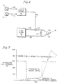
- FIG. 2 is a schematic drawing showing features of the invention.
- Figure 3 is a graphical representation showing fuel pressure through the primary and secondary nozzle orifices as a function of time.
- Figure 1 is a simplified, cross sectional view showing the combustor section 5 of a conventional gas turbine engine.
- the axis of the engine is indicated by the reference numeral A-A.
- the upstream end of the engine is indicated by the reference numeral 10 and the downstream end of the engine is indicated by the reference numeral 15.
- the key features of the combustor section 5 are the combustor 16 and the fuel nozzle 18.
- air and fuel flow through the nozzle 18 and into the combustor 16 in the direction generally indicated by arrows 20, and then pass into the turbine section 25 of the engine.
- the fuel and air mixture is ignited during engine startup by an ignitor (not shown) which is proximate to the nozzle 18.
- the first stage of the turbine section 25 begins with a row of circumferentially spaced apart turbine vanes 35.
- the outer boundary of the combustor 5 is defined by the combustor duct 40.
- the combustcr 16 has an annular shape, and the fuel nozzles 18 are circumferentially spaced about the combustor 16. At least one of the fuel nozzles is of the hybrid type, that is, it has a primary and secondary fuel orifice fed by a primary and secondary manifold, respectively.
- fuel flow to the hybrid nozzle is regulated by an electronic engine control, which is responsive to input signals received from electronic sensors arranged about the engine. These signals include a measurement of the interturbine temperature at_station 4.5 of the engine, sometimes referred to as T 4.5 ; and the high pressure compressor speed, referred to as N 2 . According to this invention, optimum engine operating conditions are met by flowing fuel to the hybrid nozzle in three regimes.
- the first fuel flow regime operates between the time engine start up is initiated to the time that the engine achieves a state of sustainable fuel combustion.
- a measure of when fuel combustion has reached a sustainable state is when T 4.5 reaches about 300 ⁇ 25°C.
- An alternate measure is N 2 speed in the range of about 11 to 13%. (N 2 speed, at any particular point of time during operation of a dual spool gas turbine engine, is typically reported as a percentage of the maximum rotational speed of the high spool of the engine.)
- the second fuel flow regime fuel flows to both the primary and secondary orifice at a fuel pressure between approximately 34.47 x 10 3 N/m 2 and 206.82 x 10 2 N/m 2 (5 and 30 psi); the second fuel flow regime is operational during the time period between achieving a state of stable fuel combustion in the combustor (approximately 300°C T 4.5 ) and the engine achieving approximately 50% N 2 speed.
- the fuel pressure to the secondary orifice during the third fuel flow regime can reach up to about 5.515 x 10 6 N/m 2 (800 psi) for take off conditions, and then decrease to approximately 4.826 x 10 6 N/m 2 (700 psi) during climb, 3.447 x 10 6 N/m 2 (500 psi) during cruise, and then back down to about 206.82 x 10 3 to 275.76 x 10 3 N/m 2 (30 to 40 psi) at ground idle conditions.
- Figure 3 graphically shows the relationship between fuel pressure through the primary and secondary orifice as a function of time of engine operation.
- Figure 3 shows fuel pressure through the primary and secondary orifice are independent of each other, except during Regime II.
- Means for achieving the fuel regimes corresponding to Figure 3 are schematically presented in Figure 2.
- primary and secondary nozzle orifices 50 and 52 respectively, feed fuel nozzle 18.
- Fuel is delivered to the orifices 50, 52 by a conventional hydromechanical unit/fuel pump 54.
- the pump 54 feeds the primary orifice through primary line manifold 56; it feeds the secondary orifice 52 through secondary line manifold 58.
- Fuel line manifold 60 connects the primary and secondary lines 56 and 58 downstream of solenoid activated valve 62.
- the valve 62 is a one-way valve, and functions in response to signals sent by engine control 64 through harness 66.
- the engine control 64 acts in response to signals received from the T 4.5 sensor 70 and N 2 sensor 74. T 4.5 signals are sent to control 64 through connecting harness 68; similarly, signals from N 2 sensor 74 are sent to engine control 64 through harness 72.
- engine control 64 deenergizes the solenoid valve 62, thereby opening the valve.
- Fuel flowing through the primary line 56 at between about 1.723 x 10 6 and 2.068 x 10 6 N/m 2 (250 and 300 psi) is delivered to primary orifice 50.
- Fuel is delivered to secondary orifice 52 through secondary line 58 at fuel pressures between approximately 6.894 . 10 3 and 34.47 x 10 3 N/m 2 (1 and 5 psi).
- T 4.5 reaches approximately 300°C
- the solenoid 62 is energized, thereby closing the primary line upstream of one way valve 60. Accordingly, no fuel flows from the pump 54 through the primary fuel manifold 56 upstream of the valve 60.
- Fuel continues to flow to the secondary line at a pressure no less than about 34.47 x 10 3 N/m 2 (5 psi), and increases up to about 206.82 x 10 3 N/m 2 (30 psi) as the engine accelerates.
- the fuel flows to the secondary orifice 52, and through the one-way valve 60 to the primary orifice 50.
- Regime II fuel flow continues until the engine nearly reaches ground idle speed, or approximately 50% N 2 speed.
- the solenoid valve 52 is de-energized. This opens the valve 60, which allows the 1.723 x 10 6 to 2.068 x 10 6 N/m 2 (250 to 300 psi) fuel to flow through the primary line 56 to the primary orifice 50.
- Fuel pressures to the secondary orifice 52 can range up to about 5.515 x 10 6 N/m 2 (800 psi) for takeoff conditions, and then decrease to about 4.826 x 10 6 N/m 2 (700 psi) for climb, 3.447 x 10 6 N/m 2 (500 psi) for cruise and back down to about 206.82 x 10 3 to 275.76 x 10 3 N/m 2 (30 to 40 psi) after the aircraft lands and the engine returns to ground idle speed.
- Use of the invention allows for safe and reliable engine starting conditions. Excessive degradation of turbine section hardware is prevented by shutting off the high pressure fuel flow to the primary orifice once stable combustion conditions are achieved; thereafter fuel pressure is increased gradually, and as air flow through the engine increases because of increasing N 2 speed, the likelihood of hot spots on turbine section hardware is minimized.
- a further advantage of the invention is that engine start time is reduced nearly 50%, in some engines, from approximately 60 seconds to 30 seconds. This is made possible because the invention allows the use of more aggressive fuel flow schedules during Regime I and Regime II operations. In particular, the rate of fuel flow to the combustor section can be nearly doubled, which accounts for the nearly 50% reduction in engine start time without fear that local hot spots will damage the turbine vane hardware.
Landscapes
- Engineering & Computer Science (AREA)
- Chemical & Material Sciences (AREA)
- Combustion & Propulsion (AREA)
- Mechanical Engineering (AREA)
- General Engineering & Computer Science (AREA)
- Feeding And Controlling Fuel (AREA)
- Control Of Turbines (AREA)
- Monitoring And Testing Of Transmission In General (AREA)
- Mobile Radio Communication Systems (AREA)
Claims (8)
- Procédé de régulation du débit de carburant dans la chambre de combustion (16) d'une turbine à gaz, ladite turbine à gaz possédant un pulvérisateur de carburant hybride (18) comprenant un premier et un second orifices (50; 52), le carburant s'écoulant d'une pompe à carburant (54) à l'orifice primaire (50) du pulvérisateur de carburant hybride (18) en passant par un distributeur de carburant primaire (56), et de la pompe à carburant (54) à l'orifice secondaire (52) en passant par un distributeur de carburant secondaire (58) dans la chambre de combustion (16) de la turbine à gaz, ledit procédé étant caractérisé par les étapes consistant à :faire s'écouler le carburant dans la chambre de combustion (16) pendant un premier régime d'écoulement du carburant dans lequel le carburant s'écoule vers l'orifice primaire (50) à une pression comprise entre environ 1,723 x 106 N/m2 et 2,068 x 106 N/m2 (250 et 300 psi) et vers l'orifice secondaire (52) à une pression comprise entre environ 6,894 x 103 N/m2 et 34,47 x 10³ N/m2 (1 et 5 psi);faire s'écouler le carburant dans la chambre de combustion (16) pendant un second régime d'écoulement du carburant dans lequel le carburant s'écoule vers les deux orifices primaire et secondaire (50; 52) à une pression comprise entre environ 34,47 x 10³ N/m2 et 206,82 x 10³ N/m2 (5 et 30 psi);et faire s'écouler le carburant dans la chambre de combustion (16) pendant un troisième régime d'écoulement du carburant dans lequel le carburant s'écoule vers l'orifice primaire (50) à une pression comprise entre 1,723 x 106 N/m2 et 2,068 x 106 N/m2 (250 et 300 psi) et vers l'orifice secondaire (52) à une pression cohérente avec le fonctionnement de la turbine dépassant de 50 % la vitesse (N2) du compresseur haute pression, le premier régime d'écoulement étant effectif entre le lancement du démarrage du moteur et l'arrivée à une combustion stable du carburant dans la chambre de combustion (16), le second régime d'écoulement étant effectif entre l'arrivée aux conditions de combustion stable du carburant et environ 50 % de la vitesse (N2) du compresseur haute pression et le troisième régime d'écoulement étant effectif ensuite.
- Procédé selon la revendication 1 comprenant l'étape consistant à mesurer la température interturbine (au poste 4.5) de la turbine et à faire cesser l'écoulement du carburant à 1,723 x 106 N/m2 et 2,068 x 106 N/m2 (250 à 300 psi) vers l'orifice primaire (50) pendant le premier régime d'écoulement lorsque cette température est comprise entre environ 275 °C et 325 °C.
- Procédé selon la revendication 1 comprenant l'étape consistant à mesurer la vitesse (N2) du compresseur haute pression de la turbine et à faire cesser l'écoulement du carburant à 1,723 x 106 N/m2 et 2,068 x 106 N/m2 (250 à 300 psi) vers l'orifice primaire (50) pendant le premier régime d'écoulement lorsque cette vitesse (N2) est comprise entre environ 11 % et 13 %.
- Procédé selon la revendication 1, dans lequel le premier régime d'écoulement de carburant comprend l'étape consistant à faire s'écouler le carburant d'une pompe à carburant (54) à l'orifice de carburant primaire (50) en passant par un distributeur de carburant primaire (56), et à faire s'écouler le carburant d'une pompe à carburant (54) à l'orifice de carburant secondaire (52) en passant par un distributeur de carburant secondaire (58).
- Procédé selon la revendication 1, dans lequel le second régime d'écoulement de carburant comprend l'étape consistant à faire s'écouler le carburant du distributeur de carburant secondaire (58) au distributeur de carburant primaire (56) à travers une soupape à une voie (60) s'étendant entre eux, de façon qu'il n'y ait pas de carburant qui s'écoule de la pompe (54) à travers le distributeur de carburant primaire (56) en direction de l'amont de la soupape (60).
- Procédé selon la revendication 1, dans lequel le troisième régime d'écoulement de carburant comprend l'étape-consistant à faire s'écouler le carburant d'une pompe à carburant (54) à l'orifice de carburant primaire (50) à travers un distributeur de carburant primaire (56) et à faire s'écouler le carburant d'une pompe à carburant (54) à l'orifice de carburant secondaire (52) à travers un distributeur de carburant secondaire (58).
- Procédé selon la revendication 5, comprenant l'étape consistant à ouvrir la soupape (60) au début du second régime d'écoulement de carburant et à fermer la soupape (60) à la fin du second régime d'écoulement de carburant.
- Procédé selon la revendication 7, dans lequel l'étape consistant à ouvrir la soupape (60) comprend l'excitation d'une bobine et l'étape consistant à fermer la soupape (60) comprend la désexcitation de la bobine.
Applications Claiming Priority (3)
| Application Number | Priority Date | Filing Date | Title |
|---|---|---|---|
| US08/085,514 US5329759A (en) | 1993-06-30 | 1993-06-30 | Method for regulating fuel flow in a gas turbine engine |
| PCT/IB1994/000150 WO1995001501A1 (fr) | 1993-06-30 | 1994-05-25 | Programme de mise en marche des regimes de pression de carburant dans une turbine a gaz |
| US85514 | 1998-05-27 |
Publications (2)
| Publication Number | Publication Date |
|---|---|
| EP0705384A1 EP0705384A1 (fr) | 1996-04-10 |
| EP0705384B1 true EP0705384B1 (fr) | 1998-01-07 |
Family
ID=22192116
Family Applications (1)
| Application Number | Title | Priority Date | Filing Date |
|---|---|---|---|
| EP94916364A Expired - Lifetime EP0705384B1 (fr) | 1993-06-30 | 1994-05-25 | Programme de mise en marche des regimes de pression de carburant dans une turbine a gaz |
Country Status (5)
| Country | Link |
|---|---|
| US (1) | US5329759A (fr) |
| EP (1) | EP0705384B1 (fr) |
| JP (1) | JPH09501213A (fr) |
| DE (1) | DE69407790T2 (fr) |
| WO (1) | WO1995001501A1 (fr) |
Cited By (2)
| Publication number | Priority date | Publication date | Assignee | Title |
|---|---|---|---|---|
| US7060332B2 (en) | 2001-04-25 | 2006-06-13 | Lg.Philips Lcd Co., Ltd. | Liquid crystal display with alignment film of polyphenylenphthalamide-based material and method for fabricating the same |
| US7429412B2 (en) | 2000-10-04 | 2008-09-30 | Lg Display Co., Ltd. | Liquid crystal display device and method for manufacturing the same |
Families Citing this family (8)
| Publication number | Priority date | Publication date | Assignee | Title |
|---|---|---|---|---|
| US6526741B2 (en) * | 2000-12-18 | 2003-03-04 | General Electric Company | Method and apparatus for removing alkali metal contamination from gas turbine liquid fuels |
| EP1278014B1 (fr) * | 2001-07-18 | 2007-01-24 | Rolls-Royce PLC | Dispositif d'alimentation en carburant |
| JP4900479B2 (ja) * | 2007-04-06 | 2012-03-21 | 株式会社日立製作所 | ガスタービン発電設備及びその起動方法 |
| US8820087B2 (en) * | 2008-09-08 | 2014-09-02 | Siemens Energy, Inc. | Method and system for controlling fuel to a dual stage nozzle |
| US8056343B2 (en) * | 2008-10-01 | 2011-11-15 | General Electric Company | Off center combustor liner |
| US8590310B2 (en) | 2012-03-27 | 2013-11-26 | Hamilton Sundstrand Corporation | Passive equilization flow divider valve |
| US20160169120A1 (en) * | 2014-12-10 | 2016-06-16 | United Technologies Corporation | Fuel Schedule for Robust Gas Turbine Engine Transition Between Steady States |
| US12221926B2 (en) | 2022-06-08 | 2025-02-11 | General Electric Company | Multi-temperature fuel injectors for a gas turbine engine |
Family Cites Families (9)
| Publication number | Priority date | Publication date | Assignee | Title |
|---|---|---|---|---|
| US4019315A (en) * | 1973-06-20 | 1977-04-26 | Westinghouse Electric Corporation | Gas turbine power plant control apparatus including a temperature reset starting control system and an ignition pressure control system |
| US4474014A (en) * | 1981-09-17 | 1984-10-02 | United Technologies Corporation | Partially unshrouded swirler for combustion chambers |
| GB2174147B (en) * | 1985-04-25 | 1989-02-01 | Rolls Royce | Improvements in or relating to the operation of gas turbine engine fuel systems |
| US4903478A (en) * | 1987-06-25 | 1990-02-27 | General Electric Company | Dual manifold fuel system |
| US4817389A (en) * | 1987-09-24 | 1989-04-04 | United Technologies Corporation | Fuel injection system |
| US4920740A (en) * | 1987-11-23 | 1990-05-01 | Sundstrand Corporation | Starting of turbine engines |
| US5165223A (en) * | 1990-12-10 | 1992-11-24 | Sundstrand Corporation | Process for starting a gas turbine and gas turbine |
| US5261222A (en) * | 1991-08-12 | 1993-11-16 | General Electric Company | Fuel delivery method for dual annular combuster |
| CA2072275A1 (fr) * | 1991-08-12 | 1993-02-13 | Phillip D. Napoli | Systeme d'alimentation en carburant pour double chambre annulaire de combustion |
-
1993
- 1993-06-30 US US08/085,514 patent/US5329759A/en not_active Expired - Lifetime
-
1994
- 1994-05-25 EP EP94916364A patent/EP0705384B1/fr not_active Expired - Lifetime
- 1994-05-25 JP JP7503378A patent/JPH09501213A/ja active Pending
- 1994-05-25 DE DE69407790T patent/DE69407790T2/de not_active Expired - Fee Related
- 1994-05-25 WO PCT/IB1994/000150 patent/WO1995001501A1/fr not_active Ceased
Cited By (2)
| Publication number | Priority date | Publication date | Assignee | Title |
|---|---|---|---|---|
| US7429412B2 (en) | 2000-10-04 | 2008-09-30 | Lg Display Co., Ltd. | Liquid crystal display device and method for manufacturing the same |
| US7060332B2 (en) | 2001-04-25 | 2006-06-13 | Lg.Philips Lcd Co., Ltd. | Liquid crystal display with alignment film of polyphenylenphthalamide-based material and method for fabricating the same |
Also Published As
| Publication number | Publication date |
|---|---|
| DE69407790T2 (de) | 1998-08-06 |
| EP0705384A1 (fr) | 1996-04-10 |
| DE69407790D1 (de) | 1998-02-12 |
| US5329759A (en) | 1994-07-19 |
| JPH09501213A (ja) | 1997-02-04 |
| WO1995001501A1 (fr) | 1995-01-12 |
Similar Documents
| Publication | Publication Date | Title |
|---|---|---|
| US9874148B2 (en) | Hybrid slinger combustion system | |
| EP3467385B1 (fr) | Procédé de fonctionnement d'un système de combustion avec des circuits de combustible principaux et pilotes | |
| US4903478A (en) | Dual manifold fuel system | |
| US5036657A (en) | Dual manifold fuel system | |
| US9683744B2 (en) | Combustion system for a gas turbine engine and method of operating same | |
| EP1671065B1 (fr) | Unite d'alimentation auxiliaire dotee d'une bague de projection de combustible rotative | |
| US4920740A (en) | Starting of turbine engines | |
| EP0705384B1 (fr) | Programme de mise en marche des regimes de pression de carburant dans une turbine a gaz | |
| EP1777394A2 (fr) | Contrôle de la formation de trainées chaudes dans une chambre de combustion de turbine à gaz | |
| US4897994A (en) | Method of starting turbine engines | |
| CA2595061C (fr) | Methode et appareil pour la commande active de l'ecoulement de carburant a un melangeur d'une chambre de combustion d'une turbine a gaz | |
| US5388396A (en) | Low carbon particle producing gas turbine combustor | |
| EP4411229B1 (fr) | Chambre de combustion pour moteur à turbine à gaz avec orifices d'injection de carburant centraux | |
| US12111056B2 (en) | Combustor with central fuel injection and downstream air mixing | |
| EP4411237B1 (fr) | Injecteur avec disque pour moteur à turbine à gaz à hydrogène | |
| US12259135B2 (en) | Combustor with fuel and air mixing plenum | |
| CA3223548A1 (fr) | Chambre de combustion comprenant un melangeur air-carburant creant un nuage mixte |
Legal Events
| Date | Code | Title | Description |
|---|---|---|---|
| PUAI | Public reference made under article 153(3) epc to a published international application that has entered the european phase |
Free format text: ORIGINAL CODE: 0009012 |
|
| 17P | Request for examination filed |
Effective date: 19951229 |
|
| AK | Designated contracting states |
Kind code of ref document: A1 Designated state(s): DE FR GB IT SE |
|
| 17Q | First examination report despatched |
Effective date: 19960326 |
|
| GRAG | Despatch of communication of intention to grant |
Free format text: ORIGINAL CODE: EPIDOS AGRA |
|
| GRAH | Despatch of communication of intention to grant a patent |
Free format text: ORIGINAL CODE: EPIDOS IGRA |
|
| GRAH | Despatch of communication of intention to grant a patent |
Free format text: ORIGINAL CODE: EPIDOS IGRA |
|
| GRAA | (expected) grant |
Free format text: ORIGINAL CODE: 0009210 |
|
| AK | Designated contracting states |
Kind code of ref document: B1 Designated state(s): DE FR GB IT SE |
|
| REF | Corresponds to: |
Ref document number: 69407790 Country of ref document: DE Date of ref document: 19980212 |
|
| ITF | It: translation for a ep patent filed | ||
| ET | Fr: translation filed | ||
| PLBE | No opposition filed within time limit |
Free format text: ORIGINAL CODE: 0009261 |
|
| STAA | Information on the status of an ep patent application or granted ep patent |
Free format text: STATUS: NO OPPOSITION FILED WITHIN TIME LIMIT |
|
| 26N | No opposition filed | ||
| REG | Reference to a national code |
Ref country code: GB Ref legal event code: IF02 |
|
| PGFP | Annual fee paid to national office [announced via postgrant information from national office to epo] |
Ref country code: SE Payment date: 20020418 Year of fee payment: 9 |
|
| PG25 | Lapsed in a contracting state [announced via postgrant information from national office to epo] |
Ref country code: SE Free format text: LAPSE BECAUSE OF NON-PAYMENT OF DUE FEES Effective date: 20030526 |
|
| EUG | Se: european patent has lapsed | ||
| PG25 | Lapsed in a contracting state [announced via postgrant information from national office to epo] |
Ref country code: IT Free format text: LAPSE BECAUSE OF NON-PAYMENT OF DUE FEES;WARNING: LAPSES OF ITALIAN PATENTS WITH EFFECTIVE DATE BEFORE 2007 MAY HAVE OCCURRED AT ANY TIME BEFORE 2007. THE CORRECT EFFECTIVE DATE MAY BE DIFFERENT FROM THE ONE RECORDED. Effective date: 20050525 |
|
| PGFP | Annual fee paid to national office [announced via postgrant information from national office to epo] |
Ref country code: DE Payment date: 20070531 Year of fee payment: 14 |
|
| PGFP | Annual fee paid to national office [announced via postgrant information from national office to epo] |
Ref country code: GB Payment date: 20080407 Year of fee payment: 15 |
|
| PG25 | Lapsed in a contracting state [announced via postgrant information from national office to epo] |
Ref country code: DE Free format text: LAPSE BECAUSE OF NON-PAYMENT OF DUE FEES Effective date: 20081202 |
|
| GBPC | Gb: european patent ceased through non-payment of renewal fee |
Effective date: 20090525 |
|
| REG | Reference to a national code |
Ref country code: FR Ref legal event code: ST Effective date: 20100129 |
|
| PG25 | Lapsed in a contracting state [announced via postgrant information from national office to epo] |
Ref country code: FR Free format text: LAPSE BECAUSE OF NON-PAYMENT OF DUE FEES Effective date: 20090602 |
|
| PGFP | Annual fee paid to national office [announced via postgrant information from national office to epo] |
Ref country code: FR Payment date: 20080424 Year of fee payment: 15 |
|
| PG25 | Lapsed in a contracting state [announced via postgrant information from national office to epo] |
Ref country code: GB Free format text: LAPSE BECAUSE OF NON-PAYMENT OF DUE FEES Effective date: 20090525 |