EP0705546A2 - Dispositif à épiler - Google Patents
Dispositif à épiler Download PDFInfo
- Publication number
- EP0705546A2 EP0705546A2 EP95117823A EP95117823A EP0705546A2 EP 0705546 A2 EP0705546 A2 EP 0705546A2 EP 95117823 A EP95117823 A EP 95117823A EP 95117823 A EP95117823 A EP 95117823A EP 0705546 A2 EP0705546 A2 EP 0705546A2
- Authority
- EP
- European Patent Office
- Prior art keywords
- blades
- pinching
- hairs
- tips
- drive means
- Prior art date
- Legal status (The legal status is an assumption and is not a legal conclusion. Google has not performed a legal analysis and makes no representation as to the accuracy of the status listed.)
- Granted
Links
- 210000004209 hair Anatomy 0.000 claims abstract description 51
- 239000013013 elastic material Substances 0.000 claims 1
- 230000010355 oscillation Effects 0.000 description 8
- 230000007935 neutral effect Effects 0.000 description 4
- 239000000463 material Substances 0.000 description 2
- 238000009499 grossing Methods 0.000 description 1
- 230000004048 modification Effects 0.000 description 1
- 238000012986 modification Methods 0.000 description 1
- 239000011148 porous material Substances 0.000 description 1
- 238000004080 punching Methods 0.000 description 1
- 238000005096 rolling process Methods 0.000 description 1
Images


Classifications
-
- A—HUMAN NECESSITIES
- A45—HAND OR TRAVELLING ARTICLES
- A45D—HAIRDRESSING OR SHAVING EQUIPMENT; EQUIPMENT FOR COSMETICS OR COSMETIC TREATMENTS, e.g. FOR MANICURING OR PEDICURING
- A45D26/00—Hair-singeing apparatus; Apparatus for removing superfluous hair, e.g. tweezers
- A45D26/0023—Hair-singeing apparatus; Apparatus for removing superfluous hair, e.g. tweezers with rotating clamping elements
- A45D26/0028—Hair-singeing apparatus; Apparatus for removing superfluous hair, e.g. tweezers with rotating clamping elements with rotating discs or blades
-
- A—HUMAN NECESSITIES
- A45—HAND OR TRAVELLING ARTICLES
- A45D—HAIRDRESSING OR SHAVING EQUIPMENT; EQUIPMENT FOR COSMETICS OR COSMETIC TREATMENTS, e.g. FOR MANICURING OR PEDICURING
- A45D26/00—Hair-singeing apparatus; Apparatus for removing superfluous hair, e.g. tweezers
- A45D26/0057—Hair-singeing apparatus; Apparatus for removing superfluous hair, e.g. tweezers with multiple elements having a translatory movement parallel to the skin
-
- A—HUMAN NECESSITIES
- A45—HAND OR TRAVELLING ARTICLES
- A45D—HAIRDRESSING OR SHAVING EQUIPMENT; EQUIPMENT FOR COSMETICS OR COSMETIC TREATMENTS, e.g. FOR MANICURING OR PEDICURING
- A45D26/00—Hair-singeing apparatus; Apparatus for removing superfluous hair, e.g. tweezers
- A45D2026/008—Details of apparatus for removing superfluous hair
- A45D2026/0085—Details of apparatus for removing superfluous hair with means for reducing noise
Definitions
- the present invention is directed to a depilating device for removing superfluous hairs from the skin for aesthetic reasons or the like, comprising: a housing with a top opening; a plurality of pinching blades accommodated within said housing and arranged along a longitudinal axis in a closely spaced relation to define small clearances between respective tips of the adjacent blades for entrapping the hairs therebetween; first drive means coupled to at least a portion of said plurality of pinching blades, for displacing at least one of a pair of adjacent blades along said longitudinal axis to repeatedly clamp the hairs between the tips of the adjacent blades, and subsequently release the hairs; second drive means coupled to said plurality of pinching blades for reciprocating said pinching blades along an arcuate path about said longitudinal axis between an extended position where the tips of the blades reach said opening in engageable relation to the hairs on the skin and an retraced position, where the tips of the blades are retracted in the housing away from said opening.
- Depilating devices are known, for example, in Japanese early patent publication (KOKAI) No. 60-156407 and in European Patent Specification No. 0,328,426.
- the devices of these patents disclose the use of a series of pinching disks supported on a shaft. Each alternate disk is driven to move in one direction at a time along an axis of the shaft in order to clamp hairs between the two adjacent disks for plucking the hairs from the user's skin.
- the prior art devices cause users pain.
- the above problem has been eliminated in an improved depilating device of the present invention.
- the depilating device in accordance with the present invention is characterized in that said second drive means is cooperative with said first drive means during reciprocating such that at least one pair of pinching blades are closing for clamping the hair when their tips move along said arcuate path from said retracted position to said extended position and keep closed in the reverse direction from said extended position to said retracted position for plucking the hair until the tips reach their initial retracted position.
- the structure of the depilating device according to the present invention is based upon finding that pulling the hairs along its direction or the orientation of the pores in the skin can well reduce the pain. With this structure, it is readily possible to catch the hairs by moving the blades along the hair in the forward swinging stroke, after which the hairs can be successfully pulled along the length of the hairs in the return stroke of the blades.
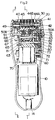
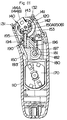
- the device comprises a housing 10 and a depilator head 20 mounted on the upper end of the housing 10 to surround a plucking assembly 40 which is responsible for removing the hairs from the skin.
- the housing 10 is composed of housing halves and incorporates an electric motor 70 for driving the plucking assembly 40.
- the motor 70 is supported by a chassis 60 together with an associated mechanism for driving the plucking assembly 40.
- the housing 10 is provided with a power switch 13 for energization of the motor 70 directly from an AC main power or through an incorporated rechargeable battery.
- a socket terminal 14 is provided in the lower end of the housing 10 for electrical connection to an AC power adaptor for charging the battery and energizing the motor 70.
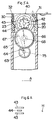
- the depilating head 20 is provided in the form of a rectangular head frame with a pair of end walls which define therebetween an opening 23 for receiving therein the plucking assembly 40.
- the depilating head 20 is detachably mounted on the upper end of the housing 10 by means of a hook 15 and carries a hair smoothening guide 30 which comes into contact with the skin of the user for smoothening the hairs prior to plucking the hairs by the plucking assembly 40.
- the guide 30 is of a rather flat rectangular configuration with a pair of side bars extending in parallel with the side walls of the head 20.
- the guide 30 is disposed within the upper end of the opening 23 and connected to a pair of pins on the end walls of the head 20 so as to swivel about the pins for easily following the contour of the skin when moving the head 20 across the skin of the user.
- the guide 30 is formed on one of the side bars with comb projections 31 and is also provided with a roller 32 extending above the other side bar and freely rotatable about corresponding pins 33 supported by the guide 30.
- the plucking assembly 40 comprises a carrier 41 rotatably supported about a shaft 42 extending horizontally between the end walls of the head 20 with its opposite ends journaled to the upper end of the chassis 60.
- the carrier 41 is provided with a series of fixed pinching plates 43 of somewhat semi-circular configuration arranged along the axis of the shaft.
- the fixed pinching plates 43 are made of a plastic material showing some elasticity and are molded integrally with the carrier 41 to provide a unitary structure. However, the fixed pinching plates 43 may be separately formed from the carrier 41.
- Also mounted on the carrier 41 are movable pinching plates 33 which are arranged along the axis of the shaft 42 in an alternating relation to the fixed pinching plates 43.
- the movable pinching plates 44 are compose of first and second plates 44A and 44B which are commonly supported loosely on the shaft 42 to be rotatable thereabout together with the carrier 41 and the fixed pinching plates 43.
- the first and second plates 44A and 44B are arranged along the axis of the shaft 42 alternately to each other and are secured at their lower ends respectively to first and second sliders 50A and 50B which are slidably supported by axles 52 held in the lower end of the carrier 41 and which are driven to reciprocate in parallel with the shaft 42 but in the opposite directions to each other, as will be discussed later.
- the chassis 60 supports, in addition to the motor 70, a positive, return cam 80 and a plurality of gears for establishing a drive connection from the motor 70 to the positive-return cam 80 as well as for oscillating the carrier 41 or the plucking assembly 40 about the shaft 42.
- the positive-return cam 80 is provided in the form of a cylinder with a pair of circumferentially extending grooves 81 which are symmetrical to each other such that the horizontal distance between the grooves varies in the circumferential direction.
- the cam 80 is supported on a horizontally extending center shaft 82 to be rotatable therewith and is operatively connected at the grooves 81 to the sliders 50A and 50B by means of universal joints. Each joint comprises a vertical swivel 91 and a horizontal swivel 92 which is inserted into a top plate 61 of the chassis 60 to be freely rotatable therein.
- the motor 70 is operatively connected to the positive-return cam 80 through a reduction gear train of a pinion 71 of the motor 70, a first gear 72 on a first shaft 73, a second gear 74 on a second shaft 75, a third gear 83 on one end of the shaft 82 of the positive-return cam 80.
- the first and second shafts 73 and 75 are held in the chassis 60 in a parallel relation to the shaft 42.
- a cam 63 is carried on one end of the second shaft 75 opposite to the second gear 74 so as to be rotatable therewith and is provided with an eccentric pin 64 which is eccentric to the axis of the second shaft 75 and which is connected to one end of a crank lever 65.
- crank lever 65 is connected to a gear wheel 66 by means of a pivot pin 67 at a point radially outwardly of a shaft 68 carrying the gear wheel 66.
- the gear wheel 66 is in meshing engagement with a gear 49 on one end of the shaft 42 of the carrier 41 so that the rotation of the eccentric pin 64 about the second shaft 75 is translated into an oscillating rotary movement of the gear wheel 66 about the shaft 68 and therefore the corresponding movement of the gear 49 or the plucking assembly 40 about the shaft 42.
- the plucking assembly 40 is caused to oscillate about the shaft 42 in synchronism with the above-described plucking movement of displacing the movable pinching plates 44 in the axial direction of the shaft 42, and is so arranged to complete one oscillation cycle while the positive-return cam 80 rotates one-half about the center shaft 82 such that the movable pinching plate 44 is caused to move toward and away from one of the two adjacent fixed pinching plates 43 during one oscillation cycle of the plucking assembly 40 about the shaft 42 and to move toward and away from the other fixed pinching plate 43 during and away from the other fixed pinching plate 43 during subsequent one oscillation cycle of the plucking assembly 40.
- the movable pinching plate 44 is caused to axially shift to have its upper end engaged with one of the two adjacent fixed pinching plates 43 to clamp the hair H therebetween, as shown in fig. 6C.
- the plucking assembly 40 is caused to rotate in the reverse direction, i.e., counter-clockwise direction in the figure to a position of fig. 5D, at which condition, the movable pinching plate 44 is kept in closed relation to the corresponding fixed pinching plate 43 so as to keep clamping the hair H therebetween, as shown in fig. 6D, to thereby pull and remove the hair H from the skin as the plucking assembly 40 rotates about the shaft 42.
- the movable pinching plate 44 is caused to move away from the fixed pinching plate 43 and returns into the neutral position, during which the hair H is released and flew circumferentially out of the plucking assembly 40 by a centrifugal force acting thereon.
- the hairs are removed along their length or directions by moving the blades along the hair in the forward swinging stroke and following pulling it along its length in the return stroke of the blades.
- the positive-return cam 80 has completed one-half rotation so that, in the immediately subsequent one oscillation cycle of the plucking assembly 49 or in subsequent one-half rotation of the cam 80, the movable pinching plate 44 is caused to move toward and away from the other fixed pinching 43 so as to cooperate therewith for effecting the like plucking operation.
- each movable pinching plate 44 is caused to move axially along the shaft 42 between the two adjacent fixed pinching plates 43 to clamp the hair with the one fixed pinching plate 43 at a time and the hair with the other fixed pinching plate 43 at the other.
- a whole distance between the two adjacent fixed plates 43 can be best utilized as an effected plucking length.
- the two adjacent movable pinching plates 44A and 44B are simultaneously brought into abutment against the one common fixed pinching plate 43 positioned therebetween to apply counterbalancing forces F to the fixed pinching plate 43 at a time, as shown in fig. 7, thus canceling otherwise occurring undesired vibrations of the fixed pinching plates 43 and therefore minimizing the operation noise.
- the first embodiment discloses to arrange the movable pinching plates 44 in an alternating relation to the fixed pinching plates 43, as shown in fig.
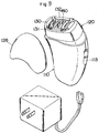
- the device comprises a depilator head 120 mounted on a housing 110 and including a plucking assembly 140.
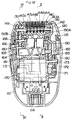
- the housing 110 incorporates a chassis 160 mounting a motor 170, a positive return cam 180, and a drive mechanism for the plucking assembly 140.
- the housing 110 is provided with a switch handle 113 for turning on and off the motor 170 and also with a pair of terminal pins 114 for electrical connection to an AC power adaptor to energize the motor 170.
- the head 120 is in the form of a top and bottom opened rectangular frame having a pair of end walls between which the plucking assembly 140 is received.
- the head 120 is detachably mounted on the upper end of the housing 110 by means of a hook 115 and carries a hair smoothening guide 130 which comes into contact with the skin of the user for smoothening the hairs prior to plucking the hairs by the plucking assembly 140.
- a head cap 128 is provided to fit over the head 120 for protection thereof when not in use.
- the guide 130 is of a rather flat rectangular configuration with a pair of side bars extending in parallel with the side walls of the head 120 and a pair of opposed end bars with center dents.
- the front side bar is slotted to give a comb projection 131 for smoothing the hairs, while the rear side bar carries a roller 132 in rolling contact with the user's skin for facilitating to move the cutter head 120 across the skin.
- the roller 132 is supported to be rotatable about a pin journaled at the opposite ends to the rear side bar.
- the plucking assembly 140 employed in the second embodiment is identical to that of the first embodiment. Therefore, no further explanation is deemed necessary but it is repeated here that the assembly 140 includes a like carrier 141 rotatably supported on a shaft 142 and mounting a number of fixed pinching plates 143 alternated by movable pinching plates 144 and that the movable pinching plates consist of first and second plates 144A and 144B which are commonly supported loosely on the shaft 142 to be rotatable thereabout together with the carrier 141 and the fixed pinching plates 143.
- first and second plates 144A and 144B are secured at their lower ends respectively to first and second sliders 150A and 150B which are slidably supported by axles 152 held in the lower end of the carrier 141 and which are driven to reciprocate in parallel with the shaft 142 but in the opposite directions to each other.
- a roller 195 is slidably received in an arcuate furrow 153 formed in the bottom of each of the sliders 150A and 150B.
- a side projection receives an offset pin 196 which extends in parallel with the center vertical shaft 193 in an opposite relation to the eccentric pin 194 from the center vertical shaft 193.
- each offset pin 196 Provided at the lower end of each offset pin 196 is a cam follower 197 for slidable engagement into each one of grooves 181 of the positive-return cam 180 such that the rotation of the cam 180 is translated into reciprocating movement of the sliders 150A and 150B along the shaft 142 through a swinging movement of the cam cylinders 190, thereby displacing the movable pinching plates 144A and 144B in the axial direction to move their upper edge into abutment and away from the associated fixed pinching plates 143.
- the positive-return cam 180 is provided in the form of a cylinder supported on a horizontally extending center shaft 182 to be rotatable therewith.
- the cam 180 is formed with a axially spaced pair of circumferentially extending grooves 181 which are symmetrical to each other such that the horizontal distance between the grooves 181 varies in the circumferential direction.
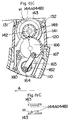
- 14A to 14E show the positions of the same movable pinching plate 144 taken during the next oscillation cycle of the plucking assembly 140.
- the plucking assembly 140 rotates in a counter-clockwise direction in the figure about the shaft 142 from the position of fig. 13A to a position of fig. 13B to rotate the movable pinching plates 144 for exposure into the opening 123 of the depilator head 120 while advancing the head 120 along the user's skin in the direction indicated by an arrow A in the figures, the movable pinching plate 144 is still kept in spaced relation to the two adjacent fixed pinching plates 143, as shown in fig.
- the plucking assembly 140 is rotated further to the position of fig. 13C while being further advanced in the direction of the arrow A, the movable pinching plate 144 is caused to axially shifted to have its upper edge engaged with one of the two adjacent fixed pinching plates 143 to clamp the hair H therebetween, as shown in fig. 14C. Thereafter, the plucking assembly 140 is caused to rotate in the reverse direction, i.e., clockwise direction in the figure to a position of fig.
- the movable pinching plate 144 is kept in closed relation to the corresponding fixed pinching plate 143 so as to keep clamping the hair H therebetween, as shown in fig. 14D, to thereby pull and remove the hair H from the skin as the plucking assembly 140 rotates about the shaft 142.
- the movable pinching plate 144 is caused to move away from the fixed pinching plate 143 and returns into the neutral position, during which the hair H is released and flew circumferentially out of the plucking assembly 140 by a centrifugal force acting thereon.
- the hairs are removed along their length or directions by moving the blades along the hair in the forward swinging stroke and following pulling it along its length in the return stroke of the blades.
- the positive-return cam 180 has completed one rotation so that, in the immediately subsequent one oscillation cycle of the plucking assembly 140 or subsequent one rotation of the cam 180, the movable pinching plate 144 is caused to move toward and away from the other fixed pinching 143, as shown in the dotted lines of figs. 14A to 14E, so as to cooperate therewith for effecting the like plucking operation.
Landscapes
- Massaging Devices (AREA)
- Surgical Instruments (AREA)
Applications Claiming Priority (10)
| Application Number | Priority Date | Filing Date | Title |
|---|---|---|---|
| JP2610491 | 1991-02-20 | ||
| JP26104/91 | 1991-02-20 | ||
| JP2610491 | 1991-02-20 | ||
| JP152786/91 | 1991-06-25 | ||
| JP15278691 | 1991-06-25 | ||
| JP3152786A JP3012362B2 (ja) | 1991-02-20 | 1991-06-25 | 脱毛装置 |
| JP33855991 | 1991-12-20 | ||
| JP338559/91 | 1991-12-20 | ||
| JP03338559A JP3056860B2 (ja) | 1991-06-25 | 1991-12-20 | 脱毛装置 |
| EP92102760A EP0500075B1 (fr) | 1991-02-20 | 1992-02-19 | Dispositif à épilation |
Related Parent Applications (2)
| Application Number | Title | Priority Date | Filing Date |
|---|---|---|---|
| EP92102760A Division EP0500075B1 (fr) | 1991-02-20 | 1992-02-19 | Dispositif à épilation |
| EP92102760.3 Division | 1992-02-19 |
Publications (3)
| Publication Number | Publication Date |
|---|---|
| EP0705546A2 true EP0705546A2 (fr) | 1996-04-10 |
| EP0705546A3 EP0705546A3 (fr) | 2003-05-21 |
| EP0705546B1 EP0705546B1 (fr) | 2005-08-24 |
Family
ID=26363843
Family Applications (1)
| Application Number | Title | Priority Date | Filing Date |
|---|---|---|---|
| EP95117823A Expired - Lifetime EP0705546B1 (fr) | 1991-02-20 | 1992-02-19 | Dispositif à épiler |
Country Status (2)
| Country | Link |
|---|---|
| EP (1) | EP0705546B1 (fr) |
| JP (1) | JP3012362B2 (fr) |
Citations (2)
| Publication number | Priority date | Publication date | Assignee | Title |
|---|---|---|---|---|
| JPS60156407A (ja) | 1983-12-22 | 1985-08-16 | ブラウン アクチェンゲゼルシャフト | 脱毛器具 |
| EP0328426A2 (fr) | 1988-02-09 | 1989-08-16 | Braun Aktiengesellschaft | Appareil à épiler |
Family Cites Families (2)
| Publication number | Priority date | Publication date | Assignee | Title |
|---|---|---|---|---|
| JP2992356B2 (ja) * | 1990-05-28 | 1999-12-20 | 松下電工株式会社 | 脱毛装置 |
| FR2663519B1 (fr) * | 1990-06-20 | 1992-10-09 | Cabrero Gilles | Appareil a epiler. |
-
1991
- 1991-06-25 JP JP3152786A patent/JP3012362B2/ja not_active Expired - Lifetime
-
1992
- 1992-02-19 EP EP95117823A patent/EP0705546B1/fr not_active Expired - Lifetime
Patent Citations (2)
| Publication number | Priority date | Publication date | Assignee | Title |
|---|---|---|---|---|
| JPS60156407A (ja) | 1983-12-22 | 1985-08-16 | ブラウン アクチェンゲゼルシャフト | 脱毛器具 |
| EP0328426A2 (fr) | 1988-02-09 | 1989-08-16 | Braun Aktiengesellschaft | Appareil à épiler |
Also Published As
| Publication number | Publication date |
|---|---|
| JP3012362B2 (ja) | 2000-02-21 |
| EP0705546A3 (fr) | 2003-05-21 |
| EP0705546B1 (fr) | 2005-08-24 |
| JPH04314403A (ja) | 1992-11-05 |
Similar Documents
| Publication | Publication Date | Title |
|---|---|---|
| EP0500075B1 (fr) | Dispositif à épilation | |
| EP0622033B1 (fr) | Appareil à épiler | |
| EP1203544B1 (fr) | Appareil à épiler portatif | |
| US5184632A (en) | Dental flossing device | |
| JP2992356B2 (ja) | 脱毛装置 | |
| CN100391701C (zh) | 脱毛装置 | |
| JP2738669B2 (ja) | 脱毛器具 | |
| EP0613632B1 (fr) | Appareil à épiler avec disques | |
| JP4869925B2 (ja) | 電気毛切断装置 | |
| US5190559A (en) | Epilating appliance | |
| KR100564831B1 (ko) | 제모 장치 | |
| US4524772A (en) | Apparatus for hair removal | |
| EP0807388A1 (fr) | Appareil d'épilation à main avec stimulateur pour marquer la douleur | |
| RU2214779C2 (ru) | Насадка к прибору для удаления волос на коже человека | |
| JPH11155627A (ja) | 脱毛装置 | |
| EP0705546B1 (fr) | Dispositif à épiler | |
| EP1072212B1 (fr) | Appareil d'épilation portatif | |
| JP2837269B2 (ja) | 脱毛装置 | |
| US5176690A (en) | Power-operated tweezers device | |
| EP0330091A3 (fr) | Dispositif pour épilation | |
| US4901723A (en) | Depilatory device | |
| US5911225A (en) | Braid detangling device | |
| US4800881A (en) | Depilating appliance | |
| JP2878386B2 (ja) | 脱毛装置 | |
| EP0476185A1 (fr) | Dispositif d'épilation |
Legal Events
| Date | Code | Title | Description |
|---|---|---|---|
| PUAI | Public reference made under article 153(3) epc to a published international application that has entered the european phase |
Free format text: ORIGINAL CODE: 0009012 |
|
| 17P | Request for examination filed |
Effective date: 19951110 |
|
| AC | Divisional application: reference to earlier application |
Ref document number: 500075 Country of ref document: EP |
|
| AK | Designated contracting states |
Kind code of ref document: A2 Designated state(s): DE FR GB IT |
|
| PUAL | Search report despatched |
Free format text: ORIGINAL CODE: 0009013 |
|
| AK | Designated contracting states |
Designated state(s): DE FR GB IT |
|
| 17Q | First examination report despatched |
Effective date: 20040102 |
|
| GRAP | Despatch of communication of intention to grant a patent |
Free format text: ORIGINAL CODE: EPIDOSNIGR1 |
|
| GRAS | Grant fee paid |
Free format text: ORIGINAL CODE: EPIDOSNIGR3 |
|
| GRAA | (expected) grant |
Free format text: ORIGINAL CODE: 0009210 |
|
| AC | Divisional application: reference to earlier application |
Ref document number: 0500075 Country of ref document: EP Kind code of ref document: P |
|
| AK | Designated contracting states |
Kind code of ref document: B1 Designated state(s): DE FR GB IT |
|
| REG | Reference to a national code |
Ref country code: GB Ref legal event code: FG4D |
|
| REF | Corresponds to: |
Ref document number: 69233544 Country of ref document: DE Date of ref document: 20050929 Kind code of ref document: P |
|
| ET | Fr: translation filed | ||
| PLBE | No opposition filed within time limit |
Free format text: ORIGINAL CODE: 0009261 |
|
| STAA | Information on the status of an ep patent application or granted ep patent |
Free format text: STATUS: NO OPPOSITION FILED WITHIN TIME LIMIT |
|
| 26N | No opposition filed |
Effective date: 20060526 |
|
| PGFP | Annual fee paid to national office [announced via postgrant information from national office to epo] |
Ref country code: FR Payment date: 20110218 Year of fee payment: 20 Ref country code: IT Payment date: 20110216 Year of fee payment: 20 Ref country code: DE Payment date: 20110216 Year of fee payment: 20 |
|
| PGFP | Annual fee paid to national office [announced via postgrant information from national office to epo] |
Ref country code: GB Payment date: 20110216 Year of fee payment: 20 |
|
| REG | Reference to a national code |
Ref country code: DE Ref legal event code: R071 Ref document number: 69233544 Country of ref document: DE |
|
| REG | Reference to a national code |
Ref country code: DE Ref legal event code: R071 Ref document number: 69233544 Country of ref document: DE |
|
| REG | Reference to a national code |
Ref country code: GB Ref legal event code: PE20 Expiry date: 20120218 |
|
| PG25 | Lapsed in a contracting state [announced via postgrant information from national office to epo] |
Ref country code: DE Free format text: LAPSE BECAUSE OF EXPIRATION OF PROTECTION Effective date: 20120220 |
|
| PG25 | Lapsed in a contracting state [announced via postgrant information from national office to epo] |
Ref country code: GB Free format text: LAPSE BECAUSE OF EXPIRATION OF PROTECTION Effective date: 20120218 |