EP0705588A1 - Medizinisches Gerät zur Ausübung einer Pumpwirkung auf den Fuss - Google Patents
Medizinisches Gerät zur Ausübung einer Pumpwirkung auf den Fuss Download PDFInfo
- Publication number
- EP0705588A1 EP0705588A1 EP95306840A EP95306840A EP0705588A1 EP 0705588 A1 EP0705588 A1 EP 0705588A1 EP 95306840 A EP95306840 A EP 95306840A EP 95306840 A EP95306840 A EP 95306840A EP 0705588 A1 EP0705588 A1 EP 0705588A1
- Authority
- EP
- European Patent Office
- Prior art keywords
- fluid
- bladder
- distal end
- foot
- tubular line
- Prior art date
- Legal status (The legal status is an assumption and is not a legal conclusion. Google has not performed a legal analysis and makes no representation as to the accuracy of the status listed.)
- Withdrawn
Links
- 238000005086 pumping Methods 0.000 title description 16
- 239000012530 fluid Substances 0.000 claims abstract description 175
- 239000000463 material Substances 0.000 claims abstract description 12
- 239000004020 conductor Substances 0.000 claims description 22
- 230000000737 periodic effect Effects 0.000 claims description 16
- 210000002683 foot Anatomy 0.000 description 50
- 230000008320 venous blood flow Effects 0.000 description 13
- 210000003462 vein Anatomy 0.000 description 10
- 230000000694 effects Effects 0.000 description 8
- 230000006641 stabilisation Effects 0.000 description 8
- 238000011105 stabilization Methods 0.000 description 8
- 210000001519 tissue Anatomy 0.000 description 7
- 230000013011 mating Effects 0.000 description 6
- 206010051055 Deep vein thrombosis Diseases 0.000 description 5
- 206010047249 Venous thrombosis Diseases 0.000 description 5
- 230000017531 blood circulation Effects 0.000 description 4
- 230000005540 biological transmission Effects 0.000 description 3
- 230000004044 response Effects 0.000 description 3
- 210000003423 ankle Anatomy 0.000 description 2
- 239000008280 blood Substances 0.000 description 2
- 210000004369 blood Anatomy 0.000 description 2
- 230000007423 decrease Effects 0.000 description 2
- 238000010586 diagram Methods 0.000 description 2
- 238000001914 filtration Methods 0.000 description 2
- 229920002635 polyurethane Polymers 0.000 description 2
- 239000004814 polyurethane Substances 0.000 description 2
- 229920000915 polyvinyl chloride Polymers 0.000 description 2
- 239000004800 polyvinyl chloride Substances 0.000 description 2
- 238000013022 venting Methods 0.000 description 2
- 239000004677 Nylon Substances 0.000 description 1
- 230000002159 abnormal effect Effects 0.000 description 1
- XECAHXYUAAWDEL-UHFFFAOYSA-N acrylonitrile butadiene styrene Chemical compound C=CC=C.C=CC#N.C=CC1=CC=CC=C1 XECAHXYUAAWDEL-UHFFFAOYSA-N 0.000 description 1
- 229920000122 acrylonitrile butadiene styrene Polymers 0.000 description 1
- 239000004676 acrylonitrile butadiene styrene Substances 0.000 description 1
- 230000003213 activating effect Effects 0.000 description 1
- 239000000853 adhesive Substances 0.000 description 1
- 230000001070 adhesive effect Effects 0.000 description 1
- 230000036772 blood pressure Effects 0.000 description 1
- 239000003990 capacitor Substances 0.000 description 1
- 210000003414 extremity Anatomy 0.000 description 1
- 230000002045 lasting effect Effects 0.000 description 1
- 238000012417 linear regression Methods 0.000 description 1
- 239000004973 liquid crystal related substance Substances 0.000 description 1
- 230000007257 malfunction Effects 0.000 description 1
- 210000001872 metatarsal bone Anatomy 0.000 description 1
- 239000004745 nonwoven fabric Substances 0.000 description 1
- 229920001778 nylon Polymers 0.000 description 1
- 230000006461 physiological response Effects 0.000 description 1
- 229920000728 polyester Polymers 0.000 description 1
- 238000000513 principal component analysis Methods 0.000 description 1
- 230000005855 radiation Effects 0.000 description 1
- 230000008961 swelling Effects 0.000 description 1
- 210000003853 toe phalanges Anatomy 0.000 description 1
- 125000000391 vinyl group Chemical group [H]C([*])=C([H])[H] 0.000 description 1
- 229920002554 vinyl polymer Polymers 0.000 description 1
- 230000000007 visual effect Effects 0.000 description 1
Images







Classifications
-
- A—HUMAN NECESSITIES
- A61—MEDICAL OR VETERINARY SCIENCE; HYGIENE
- A61H—PHYSICAL THERAPY APPARATUS, e.g. DEVICES FOR LOCATING OR STIMULATING REFLEX POINTS IN THE BODY; ARTIFICIAL RESPIRATION; MASSAGE; BATHING DEVICES FOR SPECIAL THERAPEUTIC OR HYGIENIC PURPOSES OR SPECIFIC PARTS OF THE BODY
- A61H9/00—Pneumatic or hydraulic massage
- A61H9/005—Pneumatic massage
- A61H9/0078—Pneumatic massage with intermittent or alternately inflated bladders or cuffs
-
- A—HUMAN NECESSITIES
- A61—MEDICAL OR VETERINARY SCIENCE; HYGIENE
- A61H—PHYSICAL THERAPY APPARATUS, e.g. DEVICES FOR LOCATING OR STIMULATING REFLEX POINTS IN THE BODY; ARTIFICIAL RESPIRATION; MASSAGE; BATHING DEVICES FOR SPECIAL THERAPEUTIC OR HYGIENIC PURPOSES OR SPECIFIC PARTS OF THE BODY
- A61H2201/00—Characteristics of apparatus not provided for in the preceding codes
- A61H2201/50—Control means thereof
- A61H2201/5007—Control means thereof computer controlled
-
- A—HUMAN NECESSITIES
- A61—MEDICAL OR VETERINARY SCIENCE; HYGIENE
- A61H—PHYSICAL THERAPY APPARATUS, e.g. DEVICES FOR LOCATING OR STIMULATING REFLEX POINTS IN THE BODY; ARTIFICIAL RESPIRATION; MASSAGE; BATHING DEVICES FOR SPECIAL THERAPEUTIC OR HYGIENIC PURPOSES OR SPECIFIC PARTS OF THE BODY
- A61H2205/00—Devices for specific parts of the body
- A61H2205/12—Feet
-
- A—HUMAN NECESSITIES
- A61—MEDICAL OR VETERINARY SCIENCE; HYGIENE
- A61H—PHYSICAL THERAPY APPARATUS, e.g. DEVICES FOR LOCATING OR STIMULATING REFLEX POINTS IN THE BODY; ARTIFICIAL RESPIRATION; MASSAGE; BATHING DEVICES FOR SPECIAL THERAPEUTIC OR HYGIENIC PURPOSES OR SPECIFIC PARTS OF THE BODY
- A61H2209/00—Devices for avoiding blood stagnation, e.g. Deep Vein Thrombosis [DVT] devices
Definitions
- the present invention relates generally to medical pumping apparatus and, more particularly, to such an apparatus having an inflatable bag with first and second separate fluid bladders which apply distinct compressive pressures to separate portions of a patient's foot.
- a pumping device having an inflatable bag provided with a single bladder adapted to engage between plantar limits of the ball and heel of a foot to flatten the plantar arch and stimulate venous blood flow.
- Various embodiments of the inflatable bag are disclosed. Each embodiment, however, is provided with only a single bladder which engages only a limited portion of the foot.
- optimum venous blood flow in a foot is achieved when an inflatable bag is used that engages and applies pressure to a substantial portion of the foot. Oftentimes, however, an inflatable bag that encases a substantial portion of the foot and is inflated to a pressure level required to effect venous blood flow is found by the patient to be too uncomfortable.
- the noted patent discloses a pump which communicates with the bag for cyclically inflating and deflating the bag.
- the pump is not capable of recording patient compliance data (e.g, time, date and duration of each use by the patient) for subsequent downloading to a computer in a physician's office.
- patient compliance data e.g, time, date and duration of each use by the patient
- it capable of having operating parameters input either manually or via a physician's computer.
- the pumping device in the referenced patent also fails to include means for allowing a physician to run a prescreening test prior to prescribing use of the device to a patient to ensure that the patient does not have a venous blood flow problem, such as deep vein thrombosis (DVT).
- the pumping device further lacks means for predicting for each individual patient an appropriate time period for deflation or vent cycles.
- the apparatus include a fluid generator having a controller which is capable of creating and storing patient compliance data for subsequent transmission to a physician's computer. It is also desirable that the generator include a controller that is capable of storing operating parameters set manually via a manual selector or generated via a physician's computer. It would further be desirable to have a medical pumping apparatus which includes means for allowing a physician to run a prescreening test prior to prescribing use of the device to a patient to ensure that the patient does not have a venous blood flow problem. It would additionally be desirable to have a medical pumping apparatus provided with means for predicting for each individual patient an appropriate time period for deflation cycles.
- an improved medical pumping apparatus which includes an inflatable bag having first and second bladders for applying distinct compressive pressures to separate portions of a foot.
- the second bladder which engages the heel, a forward portion of the sole and the dorsal aspect of the foot and is filled with fluid at a lower rate than that of the first bladder, compensates for reduced swelling which occurs during use.
- a fluid generator for cyclically inflating and deflating the bag.
- the fluid generator is provided with a controller that is capable of storing operating parameters set manually via a manual selector or generated by way of a physician's computer. In the latter instance, the manual selector may be partially or completely disabled to prevent subsequent manual input of one or more different operating parameters by the patient.
- the fluid generator controller is also capable of producing and saving patient compliance data for subsequent transmission to a physician's computer.
- the apparatus further includes means for allowing a physician to run a prescreening test prior to prescribing use of the device to a patient to ensure that the patient does not have a venous blood flow problem, such as deep vein thrombosis. It also includes means for predicting for each individual patient an appropriate time period for deflation cycles.
- a medical device for applying compressive pressures against a patient's foot.
- the device comprises first and second panels of flexible material secured to one another to form an inflatable bag to be fitted upon the foot.
- the bag has first and second separate fluid bladders.
- the first fluid bladder is adapted to engage a first portion of the foot and the second fluid bladder is adapted to engage a second portion of the foot.
- Securing means is provided for holding the inflatable bag to the foot.
- Fluid supply means is provided for applying pressurized fluid to the first and second fluid bladders such that the first fluid bladder applies a first compressive pressure upon the first portion of the foot and the second fluid bladder applies a second compressive pressure upon the second portion of the foot.
- the fluid supply means comprises generator means for cyclically generating fluid pulses during periodic inflation cycles. It also serves to vent fluid from the first and second bladders to atmosphere during periodic vent cycles between the inflation cycles.
- the fluid supply means further includes fluid conducting means connected to the first and second bladders and the generator means for communicating the fluid pulses generated by the generator means to the first and second bladders.
- the generator means comprises controller means for storing an operating pressure value for the fluid pulses and an operating time period for the periodic vent cycles. It also comprises manual selector means for setting a preferred pressure value to be stored by the controller means as the operating pressure value and a preferred time period to be stored by the controller means as the operating time value.
- the supply means may also include processor means associated with the generator means for generating a preferred pressure value for the fluid pulses and a preferred time period for the vent cycles.
- the processor means is coupled to the generator means for transmitting the preferred pressure value and the preferred time period to the controller means of the generator means to be stored by the controller means as the operating pressure value and the operating time period and disabling partially or completely the manual selector means whenever a preferred pressure value and a preferred time period are stored by the controller means in response to receiving same from the processor means. It is further contemplated by the present invention that processor means may be provided alone without manual selector means, or manual selector means may be provided alone without processor means.
- the controller of the generator means further provides for producing and saving patient compliance data and for transmitting the patient compliance data to the processor means.
- the operating pressure value for the fluid pulses is selected from a range of 3 to 7 psi.
- the operating pressure value is set at the value which elicits the most efficacious physiological response from the patient.
- the duration of each of the inflation cycles is approximately 3 seconds.
- the fluid conducting means comprises a first tubular line connected at its distal end to the first bladder, a second tubular line connected at its distal end to the second bladder, a third tubular line connected at its distal end to a proximal end of the first tubular line, a fourth tubular line connected at its distal end to a proximal end of the second tubular line, and a fifth tubular line connected at its distal end to proximal ends of the third and fourth tubular lines.
- the fourth tubular line is provided with a restrictive orifice for preventing delivery of fluid into the second bladder at the same rate at which fluid is delivered into the first bladder.
- the first portion of the foot comprises the plantar arch and the second portion of the foot includes the heel, a forward portion of the sole and the dorsal aspect of the foot.
- the first and second panels of flexible material may be formed from polyurethane or polyvinyl chloride.
- the securing means may comprise a boot which receives the bag and includes first and second tabs adapted to connect with one another after the boot and the bag are fitted upon a foot to hold the boot and the bag to the foot.
- the medical device may further include means for allowing a physician to run a prescreening test prior to prescribing use of the device to a patient to ensure that the patient does not have a venous blood flow problem, such as deep vein thrombosis. It may also include means for predicting for each individual patient an appropriate time period for vent cycles.
- a medical device for applying compressive pressures against a patient's foot.
- the device comprises first and second panels of flexible material secured to one another to form an inflatable bag to be fitted upon the foot, a fluid supply and a safety vent port.
- the inflatable bag has first and second separate fluid bladders.
- the first fluid bladder is adapted to engage a first portion of the foot and the second fluid bladder is adapted to engage a second portion of the foot.
- the fluid supply applies pressurized fluid to the first and second fluid bladders such that the first fluid bladder applies a first compressive pressure upon the first portion of the foot and the second fluid bladder applies a second compressive pressure upon the second portion of the foot.
- the fluid supply comprises a generator for cyclically generating fluid pulses during periodic inflation cycles, and a fluid conductor connected to the first and second bladders and the generator for communicating the fluid pulses generated by the generator to the first and second bladders.
- the safety vent port is associated with one of the first and second panels and the fluid conductor to vent pressurized fluid to atmosphere.
- the fluid conductor comprises a first tubular line connected at its distal end to the first bladder, a second tubular line connected at its distal end to the second bladder, a Y-connector connected at its first distal end to a proximal end of the first tubular line and at its second distal end to a proximal end of the second tubular line, and a third tubular line connected at its distal end to a proximal end of the Y-connector.
- the Y-connector of the fluid conductor includes the safety vent port.
- the Y-connector further includes a restrictive orifice for preventing delivery of fluid into the second bladder at the same rate at which fluid is delivered into the first bladder.
- the fluid conductor is essentially the same as the fluid conductor of the first embodiment, except that the second tubular line includes the safety vent port.
- the safety vent port is associated with one of the first and second panels.
- an inflatable bag which is adapted to be secured to a patient's foot for applying compressive pressures against the patient's foot upon receiving pressurized fluid from a fluid source.
- the bag includes first and second panels of flexible material secured to one another to form first and second separate fluid bladders.
- the first fluid bladder is adapted to engage a first portion of the foot for applying a first compressive pressure thereto and the second fluid bladder is adapted to engage a second portion of the foot for applying a second compressive pressure thereto.
- a fluid conductor is connected to the first and second bladders and the fluid source to permit the fluid source to supply pressurized fluid to the first and second bladders.
- a safety vent port is associated with one of the first and second panels and the fluid conductor to vent pressurized fluid to atmosphere.
- an object of the present invention to provide an improved medical pumping apparatus having an inflatable bag which engages a substantial portion of a patient's foot to achieve optimum blood flow at an acceptable patient comfort level. It is a further object of the present invention to provide a medical pumping apparatus having a fluid generator with a controller which is capable of producing and saving patient compliance data for subsequent transmission to a physician's computer. It is another object of the present invention to provide a medical pumping apparatus having a fluid generator with a controller that is capable of storing operating parameters set manually via a manual selector or generated by way of a physician's computer.
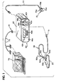
- a medical pumping apparatus 10 constructed and operable in accordance with the present invention is shown in Fig. 1.
- the apparatus includes a boot 20 adapted to be fitted upon and secured to a patient's foot.
- the boot 20 is provided with an inflatable bag 30 (see Figs. 2 and 4) which, when inflated, serves to apply compressive pressures upon the patient's foot to stimulate venous blood flow.
- the apparatus 10 further includes a fluid generator 40 which cyclically generates fluid pulses, air pulses in the illustrated embodiment, during periodic inflation cycles.
- the fluid pulses are communicated to the bag 30 via a first conducting line 50.
- the generator 40 also serves to vent fluid from the bag 30 to atmosphere during periodic vent or deflation cycles between the periodic inflation cycles.
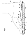
- the inflatable bag 30 is constructed from first and second panels 32 and 34 of flexible material such as polyurethane, polyvinyl chloride or the like.
- the panels 32 and 34 are heat sealed or otherwise secured to one another to form first and second fluid bladders 36 and 38, respectively.
- first fluid bladder 36 engages a patient's foot 60 approximately at the plantar arch 62, which extends between the metatarsal heads and the heel 64.
- the second fluid bladder engages the foot approximately at the dorsal aspect 66, the heel 64 and a forward portion 67 of the sole 68 of the foot 60 beneath toe phalanges.
- the exact foot portions engaged by the two bladders will vary somewhat from patient to patient.
- the boot 20 comprises a flexible outer shell 22 made from a flexible material, such as vinyl coated nylon.
- the inflatable bag is placed within the shell 22 and is adhesively bonded, heat sealed or otherwise secured thereto.
- a stiff sole member 24a formed, for example, from acrylonitrile butadiene styrene.
- the outer shell 22 is provided with first and second flaps 22a and 22b which, when fastened together, secure the boot 20 in a fitted position upon a patient's foot.
- Each of the flaps 22a and 22b is provided with patches 24 of loop-pile fastening material, such as that commonly sold under the trademark Velcro.
- a porous sheet of lining material comprising, for example, a sheet of polyester nonwoven fabric, may be placed over the upper surface 30a of the inflatable bag 30 such that it is interposed between the bag 30 and the sole 68 of the foot when the boot 20 is secured upon the foot 60.
- the fluid generator 40 includes an outer case 42 having a front panel 42a. Housed within the outer case 42 is a controller 44 which is schematically illustrated in Fig. 6.
- the controller 44 stores an operating pressure value for the fluid pulses, an operating time period for the periodic inflation cycles and an operating time period for the periodic vent cycles. In the illustrated embodiment, the operating time period for the periodic inflation cycles is fixed at 3 seconds. The other two parameters may be varied.
- the front panel 42a of the outer case 42 is provided with a keypad 42b for setting a preferred pressure value to be stored by the controller 44 as the operating pressure value.
- the preferred pressure value may be selected from a range varying from 3 to 7 psi.
- the keypad 42b is also capable of setting a preferred time period to be stored by the controller 44 as the operating time period for the periodic vent cycles.
- the preferred vent cycle time period may be selected from a range varying from 4 to 32 seconds.
- a combined time period determined by adding the time period for the inflation cycles with the time period for the vent cycles, may be set via the keypad 42b for storage by the controller 44.
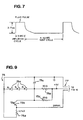
- a graphical representation of an inflation cycle followed by a vent cycle for the inflatable bag 30 is shown in Fig. 7.
- a processor 70 is provided (e.g., at a physician's office) for generating a preferred pressure value for the fluid pulses and a preferred time period for the vent cycles.
- the processor 70 is coupled to the fluid generator 40 via an interface cable 72 and transmits the preferred pressure value and the preferred time period to the controller 44 for storage by the controller 44 as the operating pressure value and the operating time period.
- the processor 70 also transmits a disabling signal to the controller 44 to effect either partial or complete disablement of the keypad 42b.
- the patient is precluded from adjusting the operating pressure value or the operating time period or both via the keypad 42b, or is permitted to adjust one or both values, but only within predefined limits.
- An operator may reactivate the keypad 42b for setting new operating parameters (i.e., to switch from the processor input mode to the keypad input mode) by actuating specific keypad buttons in a predefined manner.
- the controller 44 further provides for producing and saving patient compliance data (e.g., time, date and duration of each use by the patient), which data can be transmitted by the controller 44 to the processor 70 for storage by same.
- patient compliance data e.g., time, date and duration of each use by the patient
- an air compressor 45 Further housed within the outer case 42 is an air compressor 45, an air reservoir 46, a pressure sensor 47 and a manifold 48, as shown schematically in Fig. 8. Extending from the manifold 48 are left and right fluid lines 48a and 48b which terminate at left and right fluid outlet sockets 49a and 49b.
- the left fluid socket 49a extends through the front panel 42a of the outer case 42 for engagement with a mating connector 51 located at the proximal end of the conducting line 50, see Fig. 1.
- the conducting line 50 is secured at its distal end to the inflatable bag 30.
- the right socket 49b likewise extends through the front panel 42a for engagement with a mating connector located at the proximal end of a second conducting line (not shown) which is adapted to be connected at its distal end to a second inflatable bag (not shown).
- Compressed air generated by the compressor 45 is supplied to the reservoir 46 for storage via fluid line 44a.
- the reservoir 46 communicates with the manifold 48 via a fluid line 46a.
- An inflate solenoid, a vent solenoid, a channel solenoid and associated valves are provided within the manifold 48.
- the inflate solenoid effects the opening and closing of its associated valve to control the flow of fluid into the manifold 48 from the air reservoir 46 via fluid line 46a.
- the vent solenoid effects the opening and closing of its associated valve to control the flow of fluid from the manifold 48 to atmosphere via a vent line 48c.
- the channel solenoid effects the opening and closing of its associated valve to control the flow of fluid from the manifold 48 to fluid line 48a or fluid line 48b.
- Actuation of the solenoids is controlled by the controller 44, which is coupled to the solenoids via conductors 44a. During inflation cycles, the controller 44 actuates the vent solenoid to prevent the venting of fluid in the manifold 48 to atmosphere via vent line 48c. The controller 44 further actuates the inflate solenoid to allow pressurized air to pass from the air reservoir 46, through the manifold 48 to either the fluid line 48a or the fluid line 48b.
- the controller 44 initially causes the inflate solenoid to stop pressurized fluid from passing into the manifold 48 from the reservoir 46. It then causes the vent solenoid to open for at least an initial portion of the vent cycle and vent the fluid in the manifold 48 to atmosphere.
- the controller 44 also serves to control, via the channel solenoid, the flow of fluid to either line 48a or line 48b. If only a single boot 20 is being employed, the processor 70 does not activate the channel solenoid and line 48a, which is normally in communication with the manifold 48, communicates with the manifold 48 while line 48b is prevented from communicating with the manifold 48 by the valve associated with the channel solenoid. If two boots 20 are being employed, the controller 44 activates and deactivates the channel solenoid to alternately communicate the lines 48a and 48b with the manifold 48, thereby simulating walking.
- each boot will have its own separate inflation and vent cycles.
- an inflation cycle takes place for the other bag (not shown).
- the inflate solenoid allows pressurized fluid to pass from the air reservoir 46, through the manifold 48 and into the fluid line 48b associated with the other bag, while the channel solenoid has been activated to prevent communication of the fluid line 48a associated with the bag 30 with the manifold 48.
- the air pressure sensor 47 communicates with the manifold 48 via an air line 47a and senses the pressure level within the manifold 48, which corresponds to the pressure level which is applied to either the fluid line 48a or the fluid line 48b.
- the pressure sensor 47 transmits pressure signals to the controller 44 via conductors 47b. Based upon those pressure signals, the controller 44 controls the operation of the inflate solenoid, such as by pulse width modulation or otherwise.
- Pulse width modulation for this application comprises activating the inflate solenoid for one pulse per cycle, with the pulse lasting until the desired pressure is achieved. The length of the pulse is based upon an average of the fluid pressure level during previous inflation cycles as measured by the pressure sensor 47.
- Pulse length and hence pressure level is iteratively adjusted in small steps based on each immediately preceding pulse. In this way, the fluid pressure within the manifold 48, and thereby the pressure which is applied to either fluid line 48a or fluid-line 48b, is maintained substantially at the stored operating pressure value with no sudden changes in pressure level.
- the pressure sensor 47 is replaced by a force sensor (not shown) secured to the bag 30 so as to be interposed between the first bladder 36 and the sole 68 of the foot 60.
- the force sensor senses the force applied by the bladder 36 to the foot 60 and transmits force signals to the controller 44 which, in response, controls the operation of the inflate solenoid to maintain the fluid pressure within the manifold 48, and thereby the pressure which is applied to either fluid line 48a or fluid line 48b, at the stored operating pressure level.
- the conducting line 50 comprises a first tubular line 50a connected at its distal end to the first bladder 36, a second tubular line 50b connected at its distal end to the second bladder 38, a third tubular line 50c connected at its distal end to a proximal end of the first tubular line 50a, a fourth tubular line 50d connected at its distal end to a proximal end of the second tubular line 50b, and a fifth tubular line 50e integrally formed at its distal end with proximal ends of the third and fourth tubular lines 50c and 50d.
- the fourth tubular line 50d is provided with a restrictive orifice 53 for preventing delivery of fluid into the second bladder 38 at the same rate at which fluid is delivered into the first bladder 36. More specifically, the restrictive orifice 53 is dimensioned such that the fluid pressure in the first bladder 36 is greater than the fluid pressure level in the second bladder 38 during substantially the entirety of the inflation cycle.
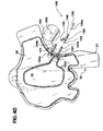
- the conducting line 150 (also referred to herein as a fluid conductor) comprises a first tubular line 152 connected at its distal end 152a to the first bladder 36, a second tubular line 154 connected at its distal end 154a to the second bladder 38, a Y-connector 160 connected at its first distal end 162 to a proximal end 152b of the first tubular line 152 and at its second distal end 164 to a proximal end 154b of the second tubular line 154, and a third tubular line 156 connected at its distal end 156a to a proximal end 166 of the Y-connector 160.
- the Y-connector 160 further includes a restrictive orifice 168 for preventing delivery of fluid into the second bladder 38 at the same rate at which fluid is delivered into the first bladder 36, see Figs. 4A and 4C.
- the restrictive orifice 168 is dimensioned such that the fluid pressure in the first bladder 36 is greater than the fluid pressure level in the second bladder 38 during substantially the entirety of the inflation cycle.
- the proximal end of the third tubular line 156 is provided with a mating connector (not shown) which is substantially similar to mating connector 51 described above.
- a safety vent port 170 is provided in the Y-connector 160, see Figs. 4A and 4C. Should a power failure occur during an inflation cycle with the vent valve in its closed position, pressurized fluid within the first and second bladders 36 and 38 will slowly decrease with time due to venting of the pressurized fluid through the safety vent port 170.
- the vent port 170 also serves to vent pressurized fluid to atmosphere in the unlikely event that the fluid generator 40 malfunctions such that the fluid generator inflate and vent solenoids and associated valves permit unrestricted flow of pressurized fluid into the bag 30.
- the dimensions of the Y-connector passages 160a and 160b, the restrictive orifice 168 and the vent port 170 can be varied in order to achieve desired inflation and vent rates.
- the conducting line 180 (also referred to herein as a fluid conductor) comprises a first tubular line 182 connected at its distal end 182a to the first bladder 36, a second tubular line 184 connected at its distal end 184a to the second bladder 38, a Y-connector 190 connected at its first distal end 192 to a proximal end 182b of the first tubular line 182 and at its second distal end 194 to a proximal end 184b of the second tubular line 184, and a third tubular line 186 connected at its distal end 186a to a proximal end 196 of the Y-connector 190.
- the Y-connector 190 further includes a restrictive orifice (not shown) which is substantially similar to restrictive orifice 168 shown in Figs. 4A and 4C.
- the restrictive orifice is dimensioned such that the fluid pressure in the first bladder 36 is greater than the fluid pressure level in the second bladder 38 during substantially the entirety of the inflation cycle.
- a safety vent port 200 is provided in the first tubular line 182 and functions in substantially the same manner as vent port 170 described above.
- the proximal end of the third tubular line 186 is provided with a mating connector (not shown) which is substantially similar to mating connector 51 described above.
- a conducting line 220 and inflatable bag 30, formed in accordance with a fourth embodiment of the present invention, are shown in Fig. 4E, where like reference numerals indicate like elements.
- the safety vent port 200' is provided in the second panel 34 of the bag 30 such that the vent port 200' communicates directly with the second bladder 38.
- the front panel 42a is further provided with a liquid crystal display (LCD) 42c for displaying the stored operating pressure value and the stored operating time period.
- LCD liquid crystal display
- the LCD 42c also serves to indicate via a visual warning if either or both of the first or second conducting lines are open or obstructed.
- Light-emitting diodes 42d are also provided for indicating whether the generator 40 is operating in the keypad input mode or the processor input mode.
- Light-emitting diodes 42f indicate which fluid outlets are active.
- pressurized fluid is transmitted to the bag 30 via the conducting line 50.
- first fluid bladder 36 applying a first compressive pressure generally at the plantar arch 62 and the second bladder 36 applying a second, distinct compressive pressure generally at the dorsal aspect 66, the heel 64 and the forward portion 67 of the sole 68 of the foot 60.
- second, distinct compressive pressure generally at the dorsal aspect 66, the heel 64 and the forward portion 67 of the sole 68 of the foot 60.
- pressurized fluid pulses are transmitted by the generator 40 to its associated inflatable bag so as to effect venous blood flow in the patient's other foot.
- the apparatus 10 further includes an infrared sensor 75, see Figs. 1 and 9.
- the sensor 75 can be used in combination with the fluid generator 40 and the processor 70 to allow a physician to prescreen patients before prescribing use of one or two of the boots 20 and the fluid generator 40.
- the prescreening test ensures that the patient does not have a venous blood flow problem, such as deep vein thrombosis.
- the prescreening test also allows the physician to predict for each individual patient a preferred time period for vent cycles.
- the senor 75 is operatively connected through the generator 40 via cable 77 to the processor 70, see Figs. 1, 6 and 9.
- the sensor 75 comprises three infrared-emitting diodes 75a which are spaced about a centrally located phototransistor 75b.
- the sensor 75 further includes a filtering capacitor 75c and three resistors 75d.
- the sensor 75 is adapted to be secured to the skin tissue of a patient's leg approximately 10 cm above the ankle via a double-sided adhesive collar (not shown) or otherwise.
- the diodes 75a emit infrared radiation or light which passes into the skin tissue. A portion of the light is absorbed by the blood in the microvascular bed of the skin tissue. A remaining portion of the light is reflected towards the phototransistor 75b.
- An analog signal generated by the phototransistor 75b varies in dependence upon the amount of light reflected towards it. Because the amount of light reflected varies with the blood volume in the skin tissue, the analog signal can be evaluated to determine the refill time for the microvascular bed in the skin tissue (also referred to herein as the LRR refill time). Determining the microvascular bed refill time by evaluating a signal generated by a phototransistor in response to light reflected from the skin tissue is generally referred to as light reflection rheography (LRR).
- LRR light reflection rheography
- the senor 75 is first secured to the patient in the manner described above.
- the patient is then instructed to perform a predefined exercise program, e.g., 10 dorsiflexions of the ankle within a predefined time period, e.g., 10 seconds.
- a predefined exercise program e.g. 10 dorsiflexions of the ankle
- a predefined time period e.g. 10 seconds.
- the venous blood pressure falls due to the dorsiflexions causing the skin vessels to empty and the amount of light reflected towards the phototransistor 75b to increase.
- the patient continues to be monitored until the skin vessels are refilled by the patient's normal blood flow.
- the signals generated by the phototransistor 75b during the prescreening test are buffered by the controller 44 and passed to the processor 70 via the interface cable 72.
- a digitizing board (not shown) is provided within the processor 70 to convert the analog signals into digital signals.
- the processor 70 filters the digital signals.
- the processor 70 filters the digital signals by taking 7 samples of sensor data and arranging those samples in sequential order from the lowest value to the highest value. It then selects the middle or "median" value and discards the remaining values. Based upon the median values, the processor 70 then plots a light reflection rheography (LRR) curve.
- LRR light reflection rheography
- the processor 70 monitors the signal generated by the sensor 75 and produces the LRR curve only after the sensor 75 has stabilized. Sensor stabilization is particularly important because, during the stabilization period, the signals generated by the sensor 75 decline at a rate close to the rate at which the skin vessels refill.
- Fig. 11 shows in flow chart form the steps which are used by the processor 70 to determine if the signal generated by the sensor 75 has stabilized.
- the first step 80 is to take 100 consecutive samples of filtered sensor data and obtain an average of those samples. After delaying approximately 0.5 second, the processor 70 takes another 100 consecutive samples of sensor data and obtains an average of those samples, see steps 81 and 82.
- the processor 70 determines the slope of a line extending between the averages of the two groups sampled.
- the processor 70 determines whether 3 minutes have passed since the sensor 75 was initially secured to the patient's skin, see step 85. Experience has shown that stabilization will occur in any event within 3 minutes. If 3 minutes have passed, the processor 70 concludes that stabilization has occurred. If not, it repeats steps 80-85.
- the processor 70 After generating the LRR curve, the processor 70 further creates an optimum refill line L r and plots the line L r for comparison by the physician with the actual LRR curve, see Fig. 10.
- the optimum refill line L r extends from the maximum point on the plotted LRR curve to a point on the baseline, which point is spaced along the X-axis by a selected number of seconds. It is currently believed that this time along the X-axis should be 30 seconds from the X-component of the maximum point; however other times close to 30 seconds may ultimately prove superior.
- the processor 70 generates the endpoint of the LRR curve and the LRR refill time.
- Fig. 12 shows in flow chart form the steps which are used by the processor 70 to determine the endpoint on the LRR curve and the refill time.
- step 90 all filtered samples for a single prescreening test are loaded into the processor 70.
- step 91 two window averages are determined. In a working embodiment of the invention, each window average is determined from 30 filtered data points, and the two window averages are separated by 5 filtered data points. Of course, other sample sizes for the windows can be used in accordance with the present invention. Further, the number of data points separating the windows can be varied.
- step 92 the slope of a line extending between the two window averages is found.
- step 93 if the slope is less than 0, the processor 70 moves the windows one data point to the right and returns to step 91. If the slope is greater than or equal to zero, the processor 70 determines the endpoint, see step 94.
- the endpoint is determined by identifying the lowest and highest data points from among all data points used in calculating the two window averages and taking the centerpoint between those identified data points.
- the processor 70 determines a preferred time period for the periodic vent cycles by estimating the refill time period for the patient's deep plantar veins based upon the determined LRR refill time. In order to determine the refill time period for the deep plantar veins, an equation is generated in the following manner.
- LRR plots for a group of patients are generated in the manner described above using the boot 20, the inflatable bag 30, the fluid generator 40, the processor 70 and the sensor 75.
- the group must include patients ranging, preferably continuously ranging, from normal to seriously abnormal.
- the LRR refill time is also generated for each of these patients.
- Refill times for the deep plantar veins are additionally determined for the patients in the group.
- the refill time is determined for each patient while he/she is fitted with the boot 20 and the inflatable bag 30 has applied compressive pressures to his/her foot.
- An accepted clinical test such as phlebography or ultrasonic doppler, is used to determine the refill time for the deep plantar veins.
- Data points having an X-component equal to the LRR refill time and a Y-component equal to the refill time for the deep plantar veins are plotted for the patients in the group. From those points a curve is generated. Linear regression or principal component analysis is employed to generate an equation for that curve.
- the equation is stored in the processor 70. From the stored equation, the processor 70 estimates for each patient undergoing the prescreening test the patient's deep plantar veins refill time processor 70 estimates for each patient undergoing the prescreening test the patient's deep plantar veins refill time based upon the LRR refill time determined for that patient.
- the preferred time period for the periodic vent cycles is set equal to the deep plantar veins refill time and that preferred time period is transmitted by the processor 70 to the controller 44 for storage by the controller 44 as the operating time period for the periodic vent cycles.
- a look-up table recorded in terms of LRR refill time and deep plantar veins refill time, could be stored within the processor 70 and used in place of the noted equation to estimate the preferred time period for the periodic vent cycles.
- a program listing (written in Basic) in accordance with the present invention including statements for (1) determining stabilization of the sensor 75; (2) median filtering; and (3) determining the endpoint of the LRR curve is set forth below:
Landscapes
- Health & Medical Sciences (AREA)
- Epidemiology (AREA)
- Pain & Pain Management (AREA)
- Physical Education & Sports Medicine (AREA)
- Rehabilitation Therapy (AREA)
- Life Sciences & Earth Sciences (AREA)
- Animal Behavior & Ethology (AREA)
- General Health & Medical Sciences (AREA)
- Public Health (AREA)
- Veterinary Medicine (AREA)
- Massaging Devices (AREA)
- Rehabilitation Tools (AREA)
Applications Claiming Priority (2)
| Application Number | Priority Date | Filing Date | Title |
|---|---|---|---|
| US320137 | 1994-10-07 | ||
| US08/320,137 US5769801A (en) | 1993-06-11 | 1994-10-07 | Medical pumping apparatus |
Publications (1)
| Publication Number | Publication Date |
|---|---|
| EP0705588A1 true EP0705588A1 (de) | 1996-04-10 |
Family
ID=23245034
Family Applications (1)
| Application Number | Title | Priority Date | Filing Date |
|---|---|---|---|
| EP95306840A Withdrawn EP0705588A1 (de) | 1994-10-07 | 1995-09-27 | Medizinisches Gerät zur Ausübung einer Pumpwirkung auf den Fuss |
Country Status (6)
| Country | Link |
|---|---|
| US (2) | US5769801A (de) |
| EP (1) | EP0705588A1 (de) |
| JP (1) | JPH08196584A (de) |
| AU (1) | AU3288795A (de) |
| CA (1) | CA2159768A1 (de) |
| ZA (1) | ZA958463B (de) |
Cited By (3)
| Publication number | Priority date | Publication date | Assignee | Title |
|---|---|---|---|---|
| WO1998031278A2 (en) | 1996-09-30 | 1998-07-23 | Kci New Technologies, Inc. | Remote controllable medical pumping apparatus |
| WO2006131733A3 (en) * | 2005-06-08 | 2007-05-31 | Bristol Myers Squibb Co | Compression device for the foot |
| CN101232855B (zh) * | 2005-06-08 | 2011-03-30 | 康沃特克科技公司 | 足部的压缩装置 |
Families Citing this family (103)
| Publication number | Priority date | Publication date | Assignee | Title |
|---|---|---|---|---|
| US6585669B2 (en) | 1996-06-07 | 2003-07-01 | Medical Dynamics Llc | Medical device for applying cyclic therapeutic action to subject's foot |
| IL121661A (en) * | 1997-08-31 | 2002-09-12 | Medical Compression Systems D | Device and method for applying pressure to organs, especially for fixation or massage of organs |
| US20070087901A1 (en) * | 1998-01-05 | 2007-04-19 | Brassil Thomas W | Therapy system |
| US6454681B1 (en) * | 1998-01-05 | 2002-09-24 | Thomas Brassil | Hand rehabilitation glove |
| US6494852B1 (en) * | 1998-03-11 | 2002-12-17 | Medical Compression Systems (Dbn) Ltd. | Portable ambulant pneumatic compression system |
| US6231532B1 (en) * | 1998-10-05 | 2001-05-15 | Tyco International (Us) Inc. | Method to augment blood circulation in a limb |
| EP0992230A3 (de) * | 1998-10-08 | 2001-08-22 | KCI Licensing, Inc. | Medizinische Pumpenvorrichtung und zugehörigem Verfahren |
| US6171270B1 (en) * | 1999-01-19 | 2001-01-09 | Jun-Shyan Gau | Apparatus for distributed air pressure massage |
| US7771376B2 (en) * | 2000-06-02 | 2010-08-10 | Midtown Technology Ltd. | Inflatable massage garment |
| IL140315A0 (en) | 2000-12-14 | 2002-02-10 | Medical Dynamics Israel 1998 L | Foot compression apparatus |
| US7245959B1 (en) | 2001-03-02 | 2007-07-17 | Scimed Life Systems, Inc. | Imaging catheter for use inside a guiding catheter |
| IL141824A (en) * | 2001-03-05 | 2008-11-03 | Flowmedic Ltd | Portable device for the enhancement of the circulation and for the prevention of stasis related deep vein thrombosis (dvt) |
| US6822343B2 (en) * | 2002-02-28 | 2004-11-23 | Texas Instruments Incorporated | Generating electric power in response to activity of a biological system |
| IL160185A0 (en) | 2004-02-02 | 2004-07-25 | Flowmedic Israel Ltd | A portable device for the enhancement of circulation of blood and lymph flow in a limb |
| US7520872B2 (en) | 2002-09-13 | 2009-04-21 | Neogen Technologies, Inc. | Closed wound drainage system |
| US6979324B2 (en) | 2002-09-13 | 2005-12-27 | Neogen Technologies, Inc. | Closed wound drainage system |
| US7815616B2 (en) | 2002-09-16 | 2010-10-19 | Boehringer Technologies, L.P. | Device for treating a wound |
| US7625362B2 (en) | 2003-09-16 | 2009-12-01 | Boehringer Technologies, L.P. | Apparatus and method for suction-assisted wound healing |
| WO2004091463A2 (en) | 2003-04-11 | 2004-10-28 | Hill-Rom Services, Inc. | System for compression therapy |
| US7942866B2 (en) | 2003-08-28 | 2011-05-17 | Boehringer Technologies, L.P. | Device for treating a wound |
| IL164286A0 (en) * | 2004-09-26 | 2005-12-18 | Benny Rousso | A portable device for the enhancement of blood circulation |
| WO2005074376A2 (en) * | 2003-09-03 | 2005-08-18 | Benny Rousso | A method and system for external counterpulsation |
| USD513324S1 (en) | 2003-12-20 | 2005-12-27 | Novamedix Distribution Limited | Impulse therapy garment |
| US7637879B2 (en) * | 2003-12-29 | 2009-12-29 | Medical Compression Systems, (Dbn) Ltd. | Method and apparatus for assisting vascular flow through external compression synchronized with venous phasic flow |
| GB0330203D0 (en) * | 2003-12-31 | 2004-02-04 | Novamedix Distrib Ltd | Garment for use in pump therapy for enhancing venous and arterial blood flow |
| US7871387B2 (en) | 2004-02-23 | 2011-01-18 | Tyco Healthcare Group Lp | Compression sleeve convertible in length |
| USD517695S1 (en) | 2004-02-23 | 2006-03-21 | Tyco Healthcare Group Ip | Compression sleeve |
| USD506553S1 (en) | 2004-02-23 | 2005-06-21 | Tyco Healthcare Group Lp | Compression sleeve |
| USD523147S1 (en) | 2004-02-23 | 2006-06-13 | Tyco Healthcare Group Lp | Compression sleeve |
| US7282038B2 (en) * | 2004-02-23 | 2007-10-16 | Tyco Healthcare Group Lp | Compression apparatus |
| US7896910B2 (en) | 2004-05-17 | 2011-03-01 | Coolsystems, Inc. | Modular apparatus for therapy of an animate body |
| US8079969B2 (en) * | 2004-06-09 | 2011-12-20 | Benny Rousso | Portable self-contained device for enhancing circulation |
| WO2006034261A2 (en) * | 2004-09-21 | 2006-03-30 | Diapedia, L.L.C. | Method for design and manufacture of insoles |
| IL164284A0 (en) * | 2004-09-26 | 2005-12-18 | Benny Rousso | A portable device for the enhancement of blood circulation |
| IL164360A0 (en) * | 2004-09-29 | 2005-12-18 | Benny Rousso | A device for providing intermittent compression toa limb |
| US20060189909A1 (en) * | 2005-02-24 | 2006-08-24 | Hurley Timothy B | Load relieving wound dressing |
| US20060241541A1 (en) * | 2005-04-20 | 2006-10-26 | Sundaram Ravikumar | Therapeutic bandage for the heel of the foot |
| US8235921B2 (en) | 2005-05-01 | 2012-08-07 | Flow Medic Limited | Computerized portable device for the enhancement of circulation |
| GB0515294D0 (en) | 2005-07-26 | 2005-08-31 | Novamedix Distrib Ltd | Limited durability closure means for an inflatable medical garment |
| US20070032754A1 (en) * | 2005-08-02 | 2007-02-08 | Walsh Richard F | Method and apparatus for treating a wound |
| US20070163147A1 (en) * | 2005-09-21 | 2007-07-19 | Cavanagh Peter R | Method for Design and Manufacture of Insoles |
| US7442175B2 (en) * | 2005-12-12 | 2008-10-28 | Tyco Healthcare Group Lp | Compression sleeve having air conduit |
| US8029451B2 (en) * | 2005-12-12 | 2011-10-04 | Tyco Healthcare Group Lp | Compression sleeve having air conduits |
| US7931606B2 (en) | 2005-12-12 | 2011-04-26 | Tyco Healthcare Group Lp | Compression apparatus |
| US7964829B2 (en) * | 2006-12-20 | 2011-06-21 | Tyco Healthcare Group Lp | Apparatus and method for making bag assembly |
| US8083712B2 (en) | 2007-03-20 | 2011-12-27 | Neogen Technologies, Inc. | Flat-hose assembly for wound drainage system |
| US8128584B2 (en) | 2007-04-09 | 2012-03-06 | Tyco Healthcare Group Lp | Compression device with S-shaped bladder |
| USD608006S1 (en) | 2007-04-09 | 2010-01-12 | Tyco Healthcare Group Lp | Compression device |
| US8162861B2 (en) | 2007-04-09 | 2012-04-24 | Tyco Healthcare Group Lp | Compression device with strategic weld construction |
| US8021388B2 (en) | 2007-04-09 | 2011-09-20 | Tyco Healthcare Group Lp | Compression device with improved moisture evaporation |
| US8109892B2 (en) | 2007-04-09 | 2012-02-07 | Tyco Healthcare Group Lp | Methods of making compression device with improved evaporation |
| US8034007B2 (en) | 2007-04-09 | 2011-10-11 | Tyco Healthcare Group Lp | Compression device with structural support features |
| US8029450B2 (en) | 2007-04-09 | 2011-10-04 | Tyco Healthcare Group Lp | Breathable compression device |
| US8016779B2 (en) | 2007-04-09 | 2011-09-13 | Tyco Healthcare Group Lp | Compression device having cooling capability |
| US8016778B2 (en) | 2007-04-09 | 2011-09-13 | Tyco Healthcare Group Lp | Compression device with improved moisture evaporation |
| US8070699B2 (en) | 2007-04-09 | 2011-12-06 | Tyco Healthcare Group Lp | Method of making compression sleeve with structural support features |
| US8506508B2 (en) | 2007-04-09 | 2013-08-13 | Covidien Lp | Compression device having weld seam moisture transfer |
| USD569985S1 (en) | 2007-06-08 | 2008-05-27 | Tyco Healthcare Group Lp | Foot cuff for therapeutic compression of a foot |
| US8388557B2 (en) | 2007-06-20 | 2013-03-05 | Remo Moomiaie-Qajar | Portable compression device |
| US7854237B2 (en) | 2007-06-28 | 2010-12-21 | Nancy Beck Irland | Fetal monitoring transducer aligning device |
| USD579116S1 (en) | 2007-07-27 | 2008-10-21 | Tyco Healthcare Group Lp | Foot cuff with tapered, blunt end |
| US9717896B2 (en) | 2007-12-18 | 2017-08-01 | Gearbox, Llc | Treatment indications informed by a priori implant information |
| US20090287120A1 (en) | 2007-12-18 | 2009-11-19 | Searete Llc, A Limited Liability Corporation Of The State Of Delaware | Circulatory monitoring systems and methods |
| US8636670B2 (en) | 2008-05-13 | 2014-01-28 | The Invention Science Fund I, Llc | Circulatory monitoring systems and methods |
| US8192380B2 (en) * | 2008-03-04 | 2012-06-05 | Tyco Healthcare Group Lp | Compression device with sole |
| US20090227920A1 (en) * | 2008-03-04 | 2009-09-10 | Tyco Healthcare Group Lp | Sole with anchor for compression foot cuff |
| US8162863B2 (en) * | 2008-03-04 | 2012-04-24 | Tyco Healthcare Group Lp | Sole with anchor for compression foot cuff |
| US20090227918A1 (en) * | 2008-03-04 | 2009-09-10 | Tyco Healthcare Group Lp | Compression device having an inflatable member with a pocket for receiving a counterforce component |
| US20090227921A1 (en) * | 2008-03-04 | 2009-09-10 | Tyco Healthcare Group Lp | Bendable sole for compression foot cuff |
| US8562549B2 (en) * | 2008-03-04 | 2013-10-22 | Covidien Lp | Compression device having an inflatable member including a frame member |
| AU2009223267B2 (en) * | 2008-03-13 | 2014-04-03 | Kci Licensing, Inc. | Foot manifolds, apparatuses, systems, and methods for applying reduced pressure to a tissue site on a foot |
| US8114117B2 (en) | 2008-09-30 | 2012-02-14 | Tyco Healthcare Group Lp | Compression device with wear area |
| US8636678B2 (en) | 2008-07-01 | 2014-01-28 | Covidien Lp | Inflatable member for compression foot cuff |
| CN104586624B (zh) | 2008-07-08 | 2018-02-16 | 阿维科斯有限公司 | 脚压迫系统 |
| US9439828B2 (en) | 2008-07-08 | 2016-09-13 | Avex, L.L.C. | Foot compression system |
| US20100022990A1 (en) * | 2008-07-25 | 2010-01-28 | Boehringer Technologies, L.P. | Pump system for negative pressure wound therapy and improvements thereon |
| US20100042028A1 (en) * | 2008-08-14 | 2010-02-18 | Albahealth, LLC | Foot wrap with inflatable bladder |
| US8235923B2 (en) | 2008-09-30 | 2012-08-07 | Tyco Healthcare Group Lp | Compression device with removable portion |
| US8387266B2 (en) * | 2008-12-02 | 2013-03-05 | Medical Minds LLC | Device for measuring a body part of a living being |
| US8151851B2 (en) * | 2009-06-17 | 2012-04-10 | Tyco Healthcare Group Lp | Apparatus for making bag assembly and method thereof |
| US8502121B2 (en) * | 2009-06-17 | 2013-08-06 | Covidien Lp | Radiofrequency welding apparatus |
| US20110214315A1 (en) * | 2010-03-05 | 2011-09-08 | Leap Frogg, Llc | Therapy shoe |
| US8652079B2 (en) | 2010-04-02 | 2014-02-18 | Covidien Lp | Compression garment having an extension |
| US10751221B2 (en) | 2010-09-14 | 2020-08-25 | Kpr U.S., Llc | Compression sleeve with improved position retention |
| US8398572B2 (en) | 2010-09-21 | 2013-03-19 | Covidien Lp | Bladder tube connection |
| US20120083712A1 (en) | 2010-09-30 | 2012-04-05 | Tyco Healthcare Group Lp | Monitoring Compliance Using Venous Refill Detection |
| US9615967B2 (en) | 2010-12-30 | 2017-04-11 | Coolsystems, Inc. | Reinforced therapeutic wrap and method |
| WO2012138980A2 (en) * | 2011-04-06 | 2012-10-11 | Coolsystems, Inc. | System for providing treatment to a mammal and method |
| US10463565B2 (en) | 2011-06-17 | 2019-11-05 | Coolsystems, Inc. | Adjustable patient therapy device |
| WO2013025481A1 (en) | 2011-08-12 | 2013-02-21 | Avex, Llc | Foot compression and electrical stimulation system |
| EP2785210B1 (de) | 2011-12-02 | 2018-06-06 | Avex, Llc | Federangetriebenes fusskompressionssystem |
| US9737454B2 (en) | 2012-03-02 | 2017-08-22 | Hill-Rom Services, Inc. | Sequential compression therapy compliance monitoring systems and methods |
| US9205021B2 (en) | 2012-06-18 | 2015-12-08 | Covidien Lp | Compression system with vent cooling feature |
| US9872812B2 (en) | 2012-09-28 | 2018-01-23 | Kpr U.S., Llc | Residual pressure control in a compression device |
| US9713563B2 (en) * | 2013-03-15 | 2017-07-25 | Compression Therapy Concepts, Inc. | Micro bleed hole connector for use in intermittent pneumatic compression devices |
| WO2015050870A1 (en) | 2013-10-01 | 2015-04-09 | Coolsystems, Inc. | Hand and foot wraps |
| WO2016022675A1 (en) | 2014-08-05 | 2016-02-11 | Coolsystems, Inc. | Integrated multisectional heat exchanger |
| WO2016118342A1 (en) * | 2015-01-20 | 2016-07-28 | Compression Solutions, Inc. | Sequential compression wrap connector and wrap |
| US10369075B2 (en) | 2015-03-03 | 2019-08-06 | Avex, Llc | Insole foot compression system and methods |
| CA3001061A1 (en) | 2015-10-09 | 2017-04-13 | Kpr U.S., Llc | Compression garment compliance |
| US20180343971A1 (en) * | 2016-01-12 | 2018-12-06 | Rakesh Kumar AGGARWAL | Venous thromboembolism prevention footwear |
| EP3207911B1 (de) | 2016-02-18 | 2019-04-03 | Hill-Rom Services, Inc. | Patientenliegevorrichtung mit integrierter gliedmassenkompressionsvorrichtung |
| US10166164B2 (en) | 2016-04-27 | 2019-01-01 | Radial Medical, Inc. | Adaptive compression therapy systems and methods |
Citations (7)
| Publication number | Priority date | Publication date | Assignee | Title |
|---|---|---|---|---|
| US2880721A (en) * | 1958-02-05 | 1959-04-07 | Laurence E Corcoran | Hand or foot carried pulsating massaging device |
| US4614179A (en) | 1985-08-08 | 1986-09-30 | Electro-Biology, Inc. | Medical appliance |
| US4624244A (en) * | 1984-10-15 | 1986-11-25 | Taheri Syde A | Device for aiding cardiocepital venous flow from the foot and leg of a patient |
| US4773397A (en) * | 1987-06-22 | 1988-09-27 | Wright Linear Pump, Inc. | Apparatus for promoting flow of a body fluid within a human limb |
| US4865020A (en) * | 1987-06-29 | 1989-09-12 | Horace Bullard | Apparatus and method for movement of blood by external pressure |
| US5025781A (en) * | 1989-05-08 | 1991-06-25 | Advanced Instruments, Inc. | Compression device with a safety pressure release |
| US5263473A (en) * | 1990-11-05 | 1993-11-23 | The Kendall Company | Compression device for the limb |
Family Cites Families (99)
| Publication number | Priority date | Publication date | Assignee | Title |
|---|---|---|---|---|
| US1492514A (en) * | 1920-02-18 | 1924-04-29 | Jensen Frank Harris | Arch support |
| GB233387A (en) * | 1924-01-04 | 1925-05-04 | Thomas Francis Farrimond | Improvements in or relating to cushioning devices for use inside footwear |
| US1608239A (en) * | 1925-12-09 | 1926-11-23 | Rosett Joshua | Therapeutic device |
| FR39629E (fr) * | 1931-01-12 | 1932-01-22 | Collins & Aikman Corp | Tissu à poil et son mode de fabrication |
| GB473639A (en) * | 1936-12-18 | 1937-10-18 | Scholl Mfg Co Ltd | Foot massaging appliance |
| GB479261A (en) * | 1937-06-09 | 1938-02-02 | Alfred Koschwitz | Device for massaging foot muscles |
| GB490341A (en) * | 1937-08-06 | 1938-08-12 | Alfred Koschwitz | Device for massaging foot muscles |
| US2531074A (en) * | 1947-06-03 | 1950-11-21 | Gerald W Miller | Pneumatic massage |
| US2694395A (en) * | 1951-05-10 | 1954-11-16 | William J Brown | Pneumatic pressure garment |
| US2638090A (en) * | 1952-02-05 | 1953-05-12 | John F Nantz | Massaging device |
| CH315458A (de) * | 1952-09-01 | 1956-08-15 | Adam Dipl Ing Demeny | Massageapparat |
| GB754883A (en) * | 1954-06-22 | 1956-08-15 | Albin Restle | Massage apparatus |
| GB813352A (en) | 1955-11-10 | 1959-05-13 | Scholl Mfg Co Ltd | Improvements in and relating to foot vibrators and housings therefor |
| US2781041A (en) * | 1955-12-02 | 1957-02-12 | Bernard D Weinberg | Progressive compression apparatus for treatment of bodily extremities |
| US3171410A (en) * | 1962-08-29 | 1965-03-02 | Jr Herbert J Towle | Pneumatic wound dressing |
| US3403673A (en) * | 1965-07-14 | 1968-10-01 | Welton Whann R | Means and method for stimulating arterial and venous blood flow |
| US3525333A (en) * | 1967-09-04 | 1970-08-25 | Mencacci Samuel | Device to stimulate peristaltic movements |
| US3774598A (en) * | 1968-01-25 | 1973-11-27 | D Wilson | Orthopedic exerciser |
| US3835845A (en) * | 1972-10-24 | 1974-09-17 | Medical Innovations Inc | Cardiac synchronization system and method |
| US3859989A (en) * | 1973-01-05 | 1975-01-14 | Theodore E Spielberg | Therapeutic cuff |
| US3811431A (en) * | 1973-01-17 | 1974-05-21 | M Apstein | Programmed venous assist pump |
| US3826249A (en) * | 1973-01-30 | 1974-07-30 | A Lee | Leg constricting apparatus |
| US3824992A (en) * | 1973-03-16 | 1974-07-23 | Clinical Technology Inc | Pressure garment |
| US3865102A (en) * | 1973-06-13 | 1975-02-11 | Hemodyne Inc | External cardiac assist apparatus |
| US3892531A (en) * | 1973-07-05 | 1975-07-01 | Beckman Instruments Inc | Apparatus for sequencing peptides and proteins |
| US3866604A (en) * | 1973-09-28 | 1975-02-18 | Avco Everett Res Lab Inc | External cardiac assistance |
| US3908642A (en) * | 1973-10-29 | 1975-09-30 | Pred Vinmont | Means for aerating and applying air pulsations within casts |
| US3865103A (en) * | 1973-11-08 | 1975-02-11 | Raymond Lee Organization Inc | Blood circulating device |
| US3892229A (en) * | 1973-12-06 | 1975-07-01 | Duane F Taylor | Apparatus for augmenting venous blood flow |
| US3920006A (en) * | 1974-01-02 | 1975-11-18 | Roy Lapidus Inc | Inflatable device for healing of tissue |
| US3942518A (en) * | 1974-03-18 | 1976-03-09 | Jobst Institute, Inc. | Therapeutic intermittent compression apparatus |
| US3976056A (en) * | 1974-05-18 | 1976-08-24 | Peter Nelson Brawn | Intermittent pressure pneumatic stocking |
| DE2430651A1 (de) * | 1974-06-26 | 1976-01-15 | Dieter W Liedtke | Fuss-massagevorrichtung |
| US3993053A (en) * | 1974-08-05 | 1976-11-23 | Murray Grossan | Pulsating massage system |
| US3888242A (en) * | 1974-08-23 | 1975-06-10 | Stephen W Harris | Compression massage boot |
| US3982531A (en) * | 1975-04-30 | 1976-09-28 | Thiokol Corporation | Inflation device for a pneumatic orthosis |
| US4030488A (en) * | 1975-10-28 | 1977-06-21 | The Kendall Company | Intermittent compression device |
| US4029087A (en) * | 1975-10-28 | 1977-06-14 | The Kendall Company | Extremity compression device |
| US4044759A (en) * | 1976-02-11 | 1977-08-30 | Bahman Ghayouran | Auto-transfusion torniquet appliance and method of utilizing the same to control flow of blood through a blood vessel |
| US4054129A (en) * | 1976-03-29 | 1977-10-18 | Alba-Waldensian, Inc. | System for applying pulsating pressure to the body |
| US4077402A (en) * | 1976-06-25 | 1978-03-07 | Benjamin Jr J Malvern | Apparatus for promoting blood circulation |
| US4091804A (en) * | 1976-12-10 | 1978-05-30 | The Kendall Company | Compression sleeve |
| US4098266A (en) * | 1976-12-27 | 1978-07-04 | Thomas P. Muchisky | Massage apparatus |
| US4453538A (en) * | 1977-04-07 | 1984-06-12 | Whitney John K | Medical apparatus |
| FR2390156A1 (fr) * | 1977-05-13 | 1978-12-08 | Dreiser Renee | Botte de pressotherapie |
| US4269175A (en) * | 1977-06-06 | 1981-05-26 | Dillon Richard S | Promoting circulation of blood |
| US4153050A (en) * | 1977-07-29 | 1979-05-08 | Alba-Waldensian, Incorporated | Pulsatile stocking and bladder therefor |
| JPS5450179A (en) * | 1977-09-29 | 1979-04-19 | Katsumasa Hara | Air massager |
| US4186732A (en) * | 1977-12-05 | 1980-02-05 | American Hospital Supply Corporation | Method and apparatus for pulsing a blood flow stimulator |
| US4206751A (en) * | 1978-03-31 | 1980-06-10 | Minnesota Mining And Manufacturing Company | Intermittent compression device |
| US4207876A (en) * | 1979-01-12 | 1980-06-17 | The Kendall Company | Compression device with ventilated sleeve |
| US4202325A (en) * | 1979-01-12 | 1980-05-13 | The Kendall Company | Compression device with improved fastening sleeve |
| US4198961A (en) * | 1979-01-12 | 1980-04-22 | The Kendall Company | Compression device with sleeve retained conduits |
| GB2055580A (en) * | 1979-03-02 | 1981-03-11 | Harpur B V C | Foot treatment machine |
| US4414963A (en) * | 1979-05-21 | 1983-11-15 | Clairol Incorporated | Massage devices |
| US4270527A (en) * | 1979-08-09 | 1981-06-02 | Armstrong Industries, Inc. | Inflatable trouser for medical use |
| US4311135A (en) * | 1979-10-29 | 1982-01-19 | Brueckner Gerald G | Apparatus to assist leg venous and skin circulation |
| DE3009408A1 (de) * | 1980-03-12 | 1981-09-17 | Leonhard Heinrich 7821 Feldberg Eck | Vorrichtung zur oedembehandlung |
| FR2481109A1 (fr) * | 1980-04-25 | 1981-10-30 | Jacquot Claude | Dispositif de massage ambulatoire opere par les variations de la pression d'un fluide localisees aux territoires corporels traites |
| US4375217A (en) * | 1980-06-04 | 1983-03-01 | The Kendall Company | Compression device with pressure determination |
| US4370975A (en) * | 1980-08-27 | 1983-02-01 | Wright Edward S | Apparatus promoting flow of a body fluid in a human limb |
| US4374518A (en) * | 1980-10-09 | 1983-02-22 | Raul Villanueva | Electronic device for pneumomassage to reduce lymphedema |
| US4372297A (en) * | 1980-11-28 | 1983-02-08 | The Kendall Company | Compression device |
| DE3100610C2 (de) * | 1981-01-12 | 1983-07-07 | Vladimir Dr.-Ing. Blazek | Meßeinrichtung zur nichtinvasiven Feststellung venöser bzw. arterieller Abfluß- und Durchflußstörungen |
| US4577626A (en) * | 1981-02-09 | 1986-03-25 | Nikki Co., Ltd. | Massager |
| US4408599A (en) * | 1981-08-03 | 1983-10-11 | Jobst Institute, Inc. | Apparatus for pneumatically controlling a dynamic pressure wave device |
| US4418690A (en) * | 1981-08-03 | 1983-12-06 | Jobst Institute, Inc. | Apparatus and method for applying a dynamic pressure wave to an extremity |
| US4402312A (en) * | 1981-08-21 | 1983-09-06 | The Kendall Company | Compression device |
| US4461301A (en) * | 1981-10-15 | 1984-07-24 | Self Regulation Systems, Inc. | Self adjusting bio-feedback method and apparatus |
| JPS58147742A (ja) * | 1982-02-25 | 1983-09-02 | Konishiroku Photo Ind Co Ltd | ハロゲン化銀カラ−写真感光材料 |
| US4502470A (en) * | 1982-09-16 | 1985-03-05 | Kiser John L | Physiologic device and method of treating the leg extremities |
| US4519395A (en) * | 1982-12-15 | 1985-05-28 | Hrushesky William J M | Medical instrument for noninvasive measurement of cardiovascular characteristics |
| US4614180A (en) * | 1984-06-18 | 1986-09-30 | Electro-Biology, Inc. | Medical appliance |
| GB2141938B (en) * | 1983-06-22 | 1986-11-12 | Arthur Michael Newsam Gardner | Medical appliance |
| US4696289C1 (en) * | 1983-06-22 | 2002-09-03 | Novamedix Distrib Ltd | Method of stimulating the venous-pump mechanism of the foot and for enhancement of arterial flow to the foot |
| GB2145196B (en) * | 1983-08-18 | 1986-04-09 | Kawaei Co Ltd | Rapid exhaust valve for use in blood circulation stimulator |
| FI68171C (fi) | 1983-11-07 | 1985-08-12 | Kalle Pekanmaeki | Anordning foer massage av kroppens extremiteter saosom av ben |
| US4574812A (en) * | 1984-04-18 | 1986-03-11 | The Kendall Company | Arterial thrombus detection system and method |
| US4721101C1 (en) * | 1984-06-18 | 2002-06-18 | Novamedix Distrib Ltd | Medical appliance for artificial actuation of the venous-pump mechanism in a human foot and for enhancement of arterial flow |
| US4753226A (en) * | 1985-04-01 | 1988-06-28 | Biomedical Engineering Development Center of Sun Yat-Sen University of Medical Science | Combination device for a computerized and enhanced type of external counterpulsation and extra-thoracic cardiac massage apparatus |
| US4702232A (en) * | 1985-10-15 | 1987-10-27 | Electro-Biology, Inc. | Method and apparatus for inducing venous-return flow |
| DE8530877U1 (de) * | 1985-10-31 | 1985-12-19 | Fa. A. Bösl, 5100 Aachen | Manschette zur Entstauung |
| US4809684A (en) * | 1985-12-16 | 1989-03-07 | Novamedix Limited | Pressure appliance for the hand for aiding circulation |
| US4846160A (en) * | 1985-12-16 | 1989-07-11 | Novamedix Limited | Method of promoting circulation in the hand |
| WO1987006371A1 (en) * | 1986-04-10 | 1987-10-22 | Hewlett Packard Limited | Expert system using pattern recognition techniques |
| FR2616064A1 (fr) * | 1987-06-05 | 1988-12-09 | Suissa Claude | Dispositif electro-pneumatique destine aux massages et/ou a l'amelioration de la circulation veinolymphatique des membres inferieurs chez la femme et/ou l'homme |
| US4858147A (en) * | 1987-06-15 | 1989-08-15 | Unisys Corporation | Special purpose neurocomputer system for solving optimization problems |
| JPS6472727A (en) * | 1987-09-14 | 1989-03-17 | Terumo Corp | Automatic hemomanometer |
| US5090417A (en) * | 1987-10-22 | 1992-02-25 | Mollan Raymond A B | Medical diagnostic apparatus |
| US4945905A (en) * | 1988-02-08 | 1990-08-07 | The Kendall Company | Compressible boot |
| US4974597A (en) * | 1988-10-05 | 1990-12-04 | Spacelabs, Inc. | Apparatus for identifying artifact in automatic blood pressure measurements |
| US5014714A (en) * | 1989-07-19 | 1991-05-14 | Spacelabs, Inc. | Method and apparatus for distinguishing between accurate and inaccurate blood pressure measurements in the presence of artifact |
| US4993420A (en) * | 1990-03-30 | 1991-02-19 | Rutgers University | Method and apparatus for noninvasive monitoring dynamic cardiac performance |
| US5157733A (en) * | 1990-06-08 | 1992-10-20 | Fuji Photo Film Co., Ltd. | Radiation image processing apparatus, determination apparatus, and radiation image read-out apparatus |
| US5121745A (en) * | 1990-07-23 | 1992-06-16 | Israel Michael B | Self-inflatable rescue mask |
| US5126967A (en) * | 1990-09-26 | 1992-06-30 | Information Storage Devices, Inc. | Writable distributed non-volatile analog reference system and method for analog signal recording and playback |
| US5207214A (en) * | 1991-03-19 | 1993-05-04 | Romano Anthony J | Synthesizing array for three-dimensional sound field specification |
| US5396896A (en) * | 1991-05-15 | 1995-03-14 | Chrono Dynamics, Ltd. | Medical pumping apparatus |
| US5288286A (en) * | 1992-02-25 | 1994-02-22 | Davis Albert D | Adjustable pressure cast for orthopedic injuries |
-
1994
- 1994-10-07 US US08/320,137 patent/US5769801A/en not_active Expired - Lifetime
-
1995
- 1995-09-27 EP EP95306840A patent/EP0705588A1/de not_active Withdrawn
- 1995-09-27 AU AU32887/95A patent/AU3288795A/en not_active Abandoned
- 1995-10-03 CA CA002159768A patent/CA2159768A1/en not_active Abandoned
- 1995-10-06 ZA ZA958463A patent/ZA958463B/xx unknown
- 1995-10-09 JP JP7261709A patent/JPH08196584A/ja active Pending
-
1997
- 1997-12-23 US US08/997,578 patent/US5931797A/en not_active Expired - Lifetime
Patent Citations (7)
| Publication number | Priority date | Publication date | Assignee | Title |
|---|---|---|---|---|
| US2880721A (en) * | 1958-02-05 | 1959-04-07 | Laurence E Corcoran | Hand or foot carried pulsating massaging device |
| US4624244A (en) * | 1984-10-15 | 1986-11-25 | Taheri Syde A | Device for aiding cardiocepital venous flow from the foot and leg of a patient |
| US4614179A (en) | 1985-08-08 | 1986-09-30 | Electro-Biology, Inc. | Medical appliance |
| US4773397A (en) * | 1987-06-22 | 1988-09-27 | Wright Linear Pump, Inc. | Apparatus for promoting flow of a body fluid within a human limb |
| US4865020A (en) * | 1987-06-29 | 1989-09-12 | Horace Bullard | Apparatus and method for movement of blood by external pressure |
| US5025781A (en) * | 1989-05-08 | 1991-06-25 | Advanced Instruments, Inc. | Compression device with a safety pressure release |
| US5263473A (en) * | 1990-11-05 | 1993-11-23 | The Kendall Company | Compression device for the limb |
Cited By (9)
| Publication number | Priority date | Publication date | Assignee | Title |
|---|---|---|---|---|
| WO1998031278A2 (en) | 1996-09-30 | 1998-07-23 | Kci New Technologies, Inc. | Remote controllable medical pumping apparatus |
| EP0906053A4 (de) * | 1996-09-30 | 2007-11-14 | Kci New Technologies Inc | Fernsteuerbare medizinische pump-vorrichtung |
| WO2006131733A3 (en) * | 2005-06-08 | 2007-05-31 | Bristol Myers Squibb Co | Compression device for the foot |
| CN101232855B (zh) * | 2005-06-08 | 2011-03-30 | 康沃特克科技公司 | 足部的压缩装置 |
| AU2006256605B2 (en) * | 2005-06-08 | 2011-11-10 | Convatec Technologies Inc. | Compression device for the foot |
| US8574180B2 (en) | 2005-06-08 | 2013-11-05 | Swelling Solutions, Inc. | Compression device for the foot |
| US9278043B2 (en) | 2005-06-08 | 2016-03-08 | Swelling Solutions, Inc. | Cuff for providing compression to a limb |
| US9463135B2 (en) | 2005-06-08 | 2016-10-11 | Swelling Solutions, Inc. | Compression device for the foot |
| US11154451B2 (en) | 2005-06-08 | 2021-10-26 | Swelling Solutions, Inc. | Compression device for the foot |
Also Published As
| Publication number | Publication date |
|---|---|
| ZA958463B (en) | 1996-05-17 |
| CA2159768A1 (en) | 1996-04-08 |
| JPH08196584A (ja) | 1996-08-06 |
| US5931797A (en) | 1999-08-03 |
| AU3288795A (en) | 1996-04-18 |
| US5769801A (en) | 1998-06-23 |
Similar Documents
| Publication | Publication Date | Title |
|---|---|---|
| US5769801A (en) | Medical pumping apparatus | |
| US5443440A (en) | Medical pumping apparatus | |
| US5840049A (en) | Medical pumping apparatus | |
| EP2314268B1 (de) | Kompressionsbehandlungssystem | |
| EP0150553B1 (de) | Medizinisches Gerät zur Ausübung einer Pumpwirkung auf die Fusssohle | |
| US9782323B2 (en) | Garment detection method and system for delivering compression treatment | |
| US6231532B1 (en) | Method to augment blood circulation in a limb | |
| EP0680310B1 (de) | Pneumatische kompressionseinrichtung zur anwendung auf medizinischem gebiet | |
| US5891065A (en) | Mobile extremity pumping apparatus | |
| US20060149171A1 (en) | Therapeutic apparatus for treating ulcers | |
| US20080097263A1 (en) | Device for mechanical stimulation of the foot support areas | |
| WO1998031278A2 (en) | Remote controllable medical pumping apparatus | |
| AU667274B2 (en) | Medical pumping apparatus | |
| EP1872763B1 (de) | Vorrichtung zur prävention und behandlung von störungen des bewegungsapparats | |
| GB2141938A (en) | Medical appliance | |
| US20250332053A1 (en) | Medical device and system for therapeutic dorsiflexion | |
| KR200272395Y1 (ko) | 에어 및 저주파를 이용한 마사지 시스템 | |
| HK1125820B (en) | An apparatus for preventing deep vein thrombosis |
Legal Events
| Date | Code | Title | Description |
|---|---|---|---|
| PUAI | Public reference made under article 153(3) epc to a published international application that has entered the european phase |
Free format text: ORIGINAL CODE: 0009012 |
|
| AK | Designated contracting states |
Kind code of ref document: A1 Designated state(s): AT BE CH DE DK ES FR GB GR IE IT LI LU NL PT SE |
|
| STAA | Information on the status of an ep patent application or granted ep patent |
Free format text: STATUS: THE APPLICATION IS DEEMED TO BE WITHDRAWN |
|
| 18D | Application deemed to be withdrawn |
Effective date: 19961011 |