EP0705659B1 - Unité d'usinage pour le traitement des joints d'angle de cadres en profilés soudés - Google Patents
Unité d'usinage pour le traitement des joints d'angle de cadres en profilés soudés Download PDFInfo
- Publication number
- EP0705659B1 EP0705659B1 EP95115864A EP95115864A EP0705659B1 EP 0705659 B1 EP0705659 B1 EP 0705659B1 EP 95115864 A EP95115864 A EP 95115864A EP 95115864 A EP95115864 A EP 95115864A EP 0705659 B1 EP0705659 B1 EP 0705659B1
- Authority
- EP
- European Patent Office
- Prior art keywords
- corner
- tool
- trimming device
- treatment
- treatment tool
- Prior art date
- Legal status (The legal status is an assumption and is not a legal conclusion. Google has not performed a legal analysis and makes no representation as to the accuracy of the status listed.)
- Expired - Lifetime
Links
Images

Classifications
-
- B—PERFORMING OPERATIONS; TRANSPORTING
- B23—MACHINE TOOLS; METAL-WORKING NOT OTHERWISE PROVIDED FOR
- B23Q—DETAILS, COMPONENTS, OR ACCESSORIES FOR MACHINE TOOLS, e.g. ARRANGEMENTS FOR COPYING OR CONTROLLING; MACHINE TOOLS IN GENERAL CHARACTERISED BY THE CONSTRUCTION OF PARTICULAR DETAILS OR COMPONENTS; COMBINATIONS OR ASSOCIATIONS OF METAL-WORKING MACHINES, NOT DIRECTED TO A PARTICULAR RESULT
- B23Q35/00—Control systems or devices for copying directly from a pattern or a master model; Devices for use in copying manually
- B23Q35/04—Control systems or devices for copying directly from a pattern or a master model; Devices for use in copying manually using a feeler or the like travelling along the outline of the pattern, model or drawing; Feelers, patterns, or models therefor
- B23Q35/08—Means for transforming movement of the feeler or the like into feed movement of tool or work
- B23Q35/10—Means for transforming movement of the feeler or the like into feed movement of tool or work mechanically only
- B23Q35/101—Means for transforming movement of the feeler or the like into feed movement of tool or work mechanically only with a pattern composed of one or more lines used simultaneously for one tool
- B23Q35/105—Means for transforming movement of the feeler or the like into feed movement of tool or work mechanically only with a pattern composed of one or more lines used simultaneously for one tool of two lines
-
- B—PERFORMING OPERATIONS; TRANSPORTING
- B23—MACHINE TOOLS; METAL-WORKING NOT OTHERWISE PROVIDED FOR
- B23C—MILLING
- B23C3/00—Milling particular work; Special milling operations; Machines therefor
- B23C3/12—Trimming or finishing edges, e.g. deburring welded corners
- B23C3/128—Trimming or finishing edges of doors and windows
Definitions
- the invention relates to a corner plastering device Machining the corner connections of from profile pieces welded frames, especially window or door frames, which has a curve contour on the inward side have, with a processing unit for removing the by welding the profile pieces to the corner connections created welding bead, the processing unit Machining tool and two positioned laterally Pushbuttons in a direction perpendicular to Pick-up level of the frame and along the corner connection is displaceable and by means of a spring preload against the Curve contour of the frame is pressed, the Machining tool as a parting or pulling knife with a V-shape converging cutting edges is formed.
- a corner plastering device with the aforementioned Features are known for example from DE 35 39 670 A1.
- a Parting knife For parting off the weld burr on an inner, in the Profile plane of a window or frame level Door frame, which is butt-welded from profile bars, is a Parting knife provided.
- the parting knife is pivotable stored in a longitudinally movable slide and over a Supported compression spring.
- a stop body points to the side the parting knife arranged on to the system of the profile surface to be machined and the Carry out swivel setting of the parting knife.
- the stop body is guided in a longitudinally displaceable manner on the knife holder and supported by a compression spring on the slide.
- This well-known Device only allows removal of welding beads or welding burrs on such profile surfaces of the Frame that is in the frame plane and between the outer Visible surfaces of the profile on the inside of a rollover or a similar profile section.
- the invention is based on the object Corner plastering device with a processing unit for Machining of the inside corner of welded parts To provide window or door frames with which also profiles with a curve contour on the inside corner in simple Can be processed efficiently and cleanly.
- the invention provides that the extensions of the flanks of the two buttons V-shaped towards each other and the cutting of the Include editing tool.
- the invention provides a corner plastering device with a Processing unit provided, by means of which also profiles with a curve contour on the inside corner precise and with a short clock frequency both mechanically and can be edited manually. Due to the elastic Spring preload slides the at least one sensing element along the curve section at the frame inner corner, whereby the machining tool along the miter of the Plastic profile pieces in the corner area and the created by welding the plastic profile pieces Removed welding bead.
- the fact that the on the profile Facing front trailing edges in their extension the assigned cutting edges of the processing tool include is an exact machining of the curve section guaranteed on the inner corner of the frame.
- buttons on a push button with a U-shaped body, at the ends of the legs formed touch flanks and between the legs, preferably detachably held Machining tool are formed. This makes each cutting edge of the V-shaped Machining tool assigned a probe element, the touch edges of the touch elements each in one Lay straight to the cutting edges of the processing tool.
- the U-shaped body with between the legs arranged processing tool is a compact unit created so that even small window frames easily can be edited.
- the processing tool has become blunt and the cutting edges have to be reground, it can reveal that the cutting edges and the flanks of the Touch element no longer lie in a straight line. For this is proceed according to the invention that the machining tool to align its cutting edges with the touch flanks of the probe element adjustable on this is held.
- Machining tool with the probe element is preferably held releasably on a tool holder, which in a housing of the processing unit perpendicular to Sliding plane for the profile to be processed can be moved is led.
- the tool holder can be at least one bearing, in particular a ball bearing inside the housing Machining unit can be moved, of course but also other guides, such as rails or the like. conceivable.
- the elastic force with which the tool holder or the machining tool with the at least one probe element held at the frame corner to be machined in contact position can, according to an advantageous embodiment of the invention are generated by using the tool holder at least one is on the housing of the processing unit supporting, preferably adjustable compression spring in one Stroke position for the installation of the processing tool or Touch element is held on the profile to be edited.
- the Adjustability of the at least one compression spring is recommended in particular to adjust the height of the To enable editing tool with touch elements.
- a constructive embodiment of the invention is on that of the holder for the machining tool opposite end of the tool holder at least one stud bolts sliding through a hole in the housing provided on which is designed as a spiral spring at least one compression spring is held.
- the machining tool with the at least one probe element floating for additional lateral movement on the Tool holder or the processing unit is stored.
- the profile pieces are offset in the area of the miter would with a rigid arrangement of machining tool and Probe only one probe in the system position on the Profile arrive while the other probe element is not making contact to the workpiece. The consequence would be that the welding ridge only would be removed unilaterally and thus incompletely.
- the frame corner can be reached at the start of processing according to the invention at least one stationary for Processing tool or the at least one probe element arranged, preferably adjustable height buttons for Creation at a reference point on the profile, such as on the top or the visible surface of the to be processed Profiles provided.
- the adjustability of the height button serves to adapt to different Profile cross sections or profile thicknesses with respect to the beginning of the Section of the curve at the inner corner of the frame.
- the profile pieces themselves and also regarding the Clamping the profile pieces on the holder of the Processing device is recommended according to the invention two on the side of the processing tool on legs provided height buttons to provide.
- the device can be used as a machine Corner plastering device for processing the inside corner from Profiles welded window or door frames be trained.
- a corner plastering device draws through its universal applicability and low Clock frequency also when processing with Curve sections on the inside corner of the frame.
- a manual corner plastering device has a receptacle for the frame to be processed or for the frame corner and one Lever mechanism for moving the processing unit along the miter of the frame corner to remove the Perform welding bead.
- the processing unit serves to remove the by Welding the plastic profile pieces at the corner connections welding bead created by window or door frames, and such window or door frame, which on the after inside or towards the pane of the frame Have curve section 12 on the inner corner.
- the Processing unit can, for example, on a tool carrier Corner plastering device can be arranged.
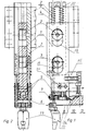
- the processing unit has one in a housing 2 in a direction perpendicular to Recording plane 16 for the window frame 10 to be processed slidably guided tool holder 1, on the for Recording for the profile 10 towards the end Machining tool 6, in particular a parting knife, is held.
- the frame 10 is only one in the figures Part shown.
- the longitudinal displaceability of the Tool holder 1 within the housing 2 takes place at the embodiment chosen here by means of ball bearings 3, which slide in elongated holes 19 of the housing 2.
- the tool holder 1 or the one held thereon Processing tool 6 is against this by means of compression springs 4 editing profile 10 pressed.
- compression springs 4 editing profile 10 pressed.
- For this are on the Recording for the processing tool 6 opposite End of the tool holder 1 through bores 17 of the housing 2 sliding stud bolts 18 are provided on which the as Coil springs formed compression springs 4 are held.
- the compression springs 4 are particularly evident from FIG. 1 between a crossbar 20 of the housing 2 and the Machining tool 6 opposite end of the Tool holder 1 clamped to an elastic force the tool holder 1 during the movement of the Machining tool 6 along the curve section 12 the miter 14 of the merged profile pieces of the frame 10 to effect.
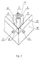
- the processing tool 6 has, as in particular from figures 3 and 4 can be seen, V-shaped, approximately at an angle of 45 ° to Miter cutting edges 8 on.
- a button 5 is provided on the inner corner of the frame, which is at a lateral distance to that by welding the Plastic profile pieces created the welding bead Curve contour 12 of the frame 10 leaves and that Machining tool 6 exactly in the miter area along the Curve contour 12 leads, so that a visually appealing frame is also generated in this area.
- the touch element 5 has an approximately U-shaped base body with his Leg ends formed touch flanks 9 and between the Legs detachably held processing tool 6. Die Touch edges 9 of the touch element 5 are in a Straight line to the assigned cutting edge 8 of the Machining tool 6.
- an offset of Be able to compensate for profile pieces in the miter area can the unit of button and processing tool 6 for one lateral movement, approximately parallel to the clamping plane 16 on the Tool carrier 1 can be stored.
- This lateral mobility of processing tool 6 with button 5 is in Figure 3 by a dash-dotted arrow is shown.
- any contour including, for example, one that corresponds the dash-dotted line shown in Figure 1 concave is machined on the inside corner of a profile 10.
- One additional adjustment of the processing tool 6 is required no more.
- the processing unit can move in different ways, for example Feed cylinders, spindles or similar drive means. Is too a manually operable by means of a lever mechanism Corner plastering device with such a processing unit can be equipped.
- This manually operated corner plastering device has For example, a recording for the frame corner to be edited on with Clamping means for pressing the frame corner against the holder.
- the lever mechanism By means of the lever mechanism the Machining unit guided along the curve section.
Landscapes
- Engineering & Computer Science (AREA)
- Mechanical Engineering (AREA)
- Automation & Control Theory (AREA)
- Milling Processes (AREA)
- Machine Tool Copy Controls (AREA)
- Bending Of Plates, Rods, And Pipes (AREA)
- Arc Welding In General (AREA)
- Soil Working Implements (AREA)
Claims (11)
- Dispositif d'ébavurage d'angle pour le traitement des assemblages d'angle de châssis soudés à partir de pièces profilées, notamment de châssis de fenêtre ou de porte (10), qui comportent un contour courbe (12) sur la face dirigée vers l'intérieur, comprenant une unité d'usinage servant à ôter le cordon de soudure se présentant sur les assemblages d'angle du fait du soudage des pièces profilées, l'unité d'usinage comportant un outil d'usinage (6) et deux palpeurs positionnés latéralement par rapport à celui-ci, étant déplaçable suivant une direction perpendiculaire au plan de réception (16) du châssis et le long de l'assemblage d'angle et étant appliquée au moyen d'une précontrainte élastique en appui sur le contour courbe (12) du châssis, tandis que l'outil d'usinage est réalisé sous forme d'une lame de coupe ou lame à rectifier comportant des parties de taille (8) s'étendant en V l'une par rapport à l'autre, caractérisé en ce que les prolongements des flancs de palpage (9) des deux palpeurs s'étendent en V l'un vers l'autre et contiennent les parties de taille (8) de l'outil d'usinage (6).
- Dispositif d'ébavurage d'angle suivant la revendication 1, caractérisé en ce que les palpeurs sont réalisés sur un élément de palpage (5) comportant un corps de base en U, des flancs de palpage (9) formés sur les extrémités de ses branches et un outil d'usinage (6) monté, de préférence d'une manière amovible, entre les branches (15).
- Dispositif d'ébavurage d'angle suivant la revendication 1 ou 2, caractérisé en ce que l'outil d'usinage (6) est maintenu sur l'élément de palpage (5) d'une manière réglable en vue de l'alignement de ses parties de taille (8) avec les flancs de palpage (9) de l'élément de palpage (5).
- Dispositif d'ébavurage d'angle suivant la revendication 2 ou 3, caractérisé en ce que l'outil d'usinage (6) est mobile le long des branches de l'élément de palpage (5), de préférence au moyen d'une vis de réglage (7).
- Dispositif d'ébavurage d'angle suivant l'une des revendications précédentes, caractérisé en ce que l'outil d'usinage (6) comportant l'élément de palpage (5) est maintenu sur l'unité d'usinage de façon à pouvoir être soumis à un déplacement de compensation transversalement par rapport à l'assemblage d'angle.
- Dispositif d'ébavurage suivant l'une des revendications 2 à 6, caractérisé en ce que l'outil d'usinage (6) comportant l'élément de palpage (5) est maintenu, de préférence d'une manière amovible, sur un porte-outil (1) qui est guidé d'une manière coulissante dans un boítier (2) de l'unité d'usinage.
- Dispositif d'ébavurage d'angle suivant la revendication 6, caractérisé en ce que le porte-outil (1) est mobile à l'intérieur du boítier (2) de l'unité d'usinage au moyen d'au moins un roulement, notamment d'un roulement à billes (3).
- Dispositif d'ébavurage d'angle suivant la revendication 6 ou 7, caractérisé en ce que le porte-outil (1) est maintenu, au moyen d'au coins un ressort de compression (4) prenant appui sur le boítier (2) de l'unité d'usinage et de préférence réglable, dans une position de poussée servant à l'appui de l'outil d'usinage (6) ou de l'élément de palpage (5) sur le profilé (10) à usiner.
- Dispositif d'ébavurage d'angle suivant l'une des revendications 6 à 8, caractérisé en ce que, sur l'extrémité du porte-outil (1) située à l'opposé de l'élément de réception prévu pour l'outil d'usinage (6), il est prévu au moins un tirant (18) qui coulisse dans un alésage (17) du boítier (2) et sur lequel est maintenu le ressort de compression (4) constitué d'un ressort hélicoïdal.
- Dispositif d'ébavurage d'angle suivant l'une des revendications précédentes, caractérisé en ce que, pour régler la hauteur de l'outil d'usinage (6) ou de l'élément de palpage (5), il est prévu au moins un palpeur de hauteur (11), de préférence réglable, qui est disposé à demeure par rapport à l'outil d'usinage (6) et qui est destiné à venir en appui sur un point de référence du profilé (10) à usiner.
- Dispositif d'ébavurage d'angle suivant la revendication 10, caractérisé en ce qu'il est prévu deux palpeurs de hauteur (11) maintenus sur les branches (15) transversalement par rapport à l'outil d'usinage (6).
Applications Claiming Priority (2)
| Application Number | Priority Date | Filing Date | Title |
|---|---|---|---|
| DE4435820 | 1994-10-07 | ||
| DE4435820 | 1994-10-07 |
Publications (2)
| Publication Number | Publication Date |
|---|---|
| EP0705659A1 EP0705659A1 (fr) | 1996-04-10 |
| EP0705659B1 true EP0705659B1 (fr) | 2000-01-12 |
Family
ID=6530161
Family Applications (1)
| Application Number | Title | Priority Date | Filing Date |
|---|---|---|---|
| EP95115864A Expired - Lifetime EP0705659B1 (fr) | 1994-10-07 | 1995-10-09 | Unité d'usinage pour le traitement des joints d'angle de cadres en profilés soudés |
Country Status (3)
| Country | Link |
|---|---|
| EP (1) | EP0705659B1 (fr) |
| AT (1) | ATE188640T1 (fr) |
| DE (1) | DE59507599D1 (fr) |
Cited By (4)
| Publication number | Priority date | Publication date | Assignee | Title |
|---|---|---|---|---|
| DE20115903U1 (de) * | 2001-09-27 | 2003-02-06 | Urban Gmbh & Co Maschinenbau Kg, 87700 Memmingen | Vorrichtung zur spanabhebenden Bearbeitung von Eckverbindungen von aus Kunststoffprofilen geschweißten Rahmen |
| DE102012107750A1 (de) * | 2012-08-22 | 2014-02-27 | Rotox Besitz-Und Verwaltungsgesellschaft Mbh | Verfahren und Vorrichtung zum Bearbeiten von Eckverbindungen aus Profilstücken, insbesondere Kunststoff-Profilstücken, geschweißter Rahmen |
| DE102013112814A1 (de) | 2013-11-20 | 2015-05-21 | Rotox Besitz-Und Verwaltungsgesellschaft Mbh | Eckverputzvorrichtung |
| DE102023114066A1 (de) | 2023-05-30 | 2024-12-05 | Rotox Holding Gmbh & Co. Kg | Eckenverputzvorrichtung |
Families Citing this family (8)
| Publication number | Priority date | Publication date | Assignee | Title |
|---|---|---|---|---|
| GB2363353B (en) * | 2000-06-16 | 2003-10-08 | Paul David Moll | Weld seam cleaner |
| DE50202892D1 (de) * | 2001-09-28 | 2005-06-02 | Eisenbach B Rotox Gmbh | Vorrichtung zum Entfernen der überstehenden Schweissraupen an den Eckverbindungen von aus Kunststoffprofilen zusammengeschweissten Fenster- oder Türrahmen |
| DE202004012786U1 (de) | 2003-12-16 | 2005-05-04 | Urban Gmbh & Co. Maschinenbau Kg | Eckverputzvorrichtung |
| DE102004014545A1 (de) * | 2004-03-23 | 2005-10-20 | Eisenbach B Rotox Gmbh | Verfahren und Vorrichtung zum Entfernen der überstehenden Schweißraupen an den Eckverbindungen von aus Kunststoffprofilen zusammengeschweißten Fenster- oder Türrahmen |
| DE102007017839A1 (de) * | 2007-04-16 | 2008-11-06 | Crasser Maschinen Gmbh | Vorrichtung und Verfahren zum konturgetreuen Abtrennen von Überständen an Profilverbindungen |
| DE202017102951U1 (de) * | 2017-05-16 | 2018-08-17 | URBAN Machinery Corp. | Verputzvorrichtung |
| CN113941729B (zh) * | 2021-11-05 | 2022-07-26 | 济南泰成科技有限公司 | 一种浮动式刻槽机 |
| EP4699791A1 (fr) | 2025-09-01 | 2026-02-25 | Awgtech Spolka z Ograniczona Odpowiedzialnoscia | Dispositif de soudage pour joindre des profilés en matière plastique, en particulier des cadres de fenêtre ou de porte, machine pour souder des profilés et procédé de soudage d'éléments profilés. |
Family Cites Families (4)
| Publication number | Priority date | Publication date | Assignee | Title |
|---|---|---|---|---|
| DE3539670A1 (de) * | 1985-11-08 | 1987-05-14 | Bernhard Eisenbach | Vorrichtung zum abstechen des schweissgrates an fenster- oder tuerrahmen |
| DE8907514U1 (de) * | 1989-06-20 | 1989-08-24 | Aquatop Produktentwicklung und Vertrieb von Reaktionsformteilen GmbH, 6277 Bad Camberg | Anbauvorrichtung für ein Handfräsgerät |
| DE4237939C2 (de) | 1992-11-11 | 1999-07-29 | Eisenbach B Rotox Gmbh | Eckenverputzvorrichtung mit drehbarem Werkzeugträger |
| GB2283193A (en) * | 1993-09-24 | 1995-05-03 | Jade Engineering | Profile trimming apparatus |
-
1995
- 1995-10-09 AT AT95115864T patent/ATE188640T1/de active
- 1995-10-09 EP EP95115864A patent/EP0705659B1/fr not_active Expired - Lifetime
- 1995-10-09 DE DE59507599T patent/DE59507599D1/de not_active Expired - Lifetime
Cited By (6)
| Publication number | Priority date | Publication date | Assignee | Title |
|---|---|---|---|---|
| DE20115903U1 (de) * | 2001-09-27 | 2003-02-06 | Urban Gmbh & Co Maschinenbau Kg, 87700 Memmingen | Vorrichtung zur spanabhebenden Bearbeitung von Eckverbindungen von aus Kunststoffprofilen geschweißten Rahmen |
| DE102012107750A1 (de) * | 2012-08-22 | 2014-02-27 | Rotox Besitz-Und Verwaltungsgesellschaft Mbh | Verfahren und Vorrichtung zum Bearbeiten von Eckverbindungen aus Profilstücken, insbesondere Kunststoff-Profilstücken, geschweißter Rahmen |
| DE102012107750B4 (de) * | 2012-08-22 | 2015-09-03 | Rotox Besitz-Und Verwaltungsgesellschaft Mbh | Vorrichtung zum Bearbeiten von Eckverbindungen aus Profilstücken, insbesondere Kunststoff-Profilstücken, geschweißter Rahmen |
| DE102013112814A1 (de) | 2013-11-20 | 2015-05-21 | Rotox Besitz-Und Verwaltungsgesellschaft Mbh | Eckverputzvorrichtung |
| EP2875887A1 (fr) | 2013-11-20 | 2015-05-27 | Rotox Besitz- und Verwaltungsgesellschaft mbH | Appareil pour enlever des bavures de coins |
| DE102023114066A1 (de) | 2023-05-30 | 2024-12-05 | Rotox Holding Gmbh & Co. Kg | Eckenverputzvorrichtung |
Also Published As
| Publication number | Publication date |
|---|---|
| ATE188640T1 (de) | 2000-01-15 |
| DE59507599D1 (de) | 2000-02-17 |
| EP0705659A1 (fr) | 1996-04-10 |
Similar Documents
| Publication | Publication Date | Title |
|---|---|---|
| EP2974824B1 (fr) | Système de guidage doté d'une machine-outil portative et rails de guidage | |
| EP1894654B1 (fr) | Procédé et unité de traitement destinée au traitement des liaisons angulaires de cadres soudés à partir de pièces de profilés | |
| EP0705659A1 (fr) | Unité d'usinage pour le traitement des joints d'angle de cadres en profilés soudés | |
| EP0598079A1 (fr) | Capot de protection pour machines-outils a travailler le bois. | |
| DE4232289A1 (de) | Verfahren und vorrichtung zum verschwenken eines fensterrahmens im bereich einer eckenputzmaschine | |
| EP1537970B1 (fr) | Dispositif d'ébarbage | |
| DE10029195C1 (de) | Vorrichtung und Verfahren zum Durchtrennen von stabförmigen Werkstücken | |
| DE9016090U1 (de) | Vorrichtung zum Zwangsführen eines Gerätes | |
| DE60036293T2 (de) | Vorrichtung zur Herstellung von Einkerbungen in die Flanke von Seitenleisten und ein der Einkerbung entsprechender Querschnitt am Ende der Querleisten zur Herstellung einer Stabverbindung zwischen den Seitenleisten und den Querleiten | |
| EP0024251A2 (fr) | Scie avec un outil rotatif en forme de tige | |
| EP1297923B2 (fr) | Unité d'usinage pour enlever des bavures de soudage des joints d'angle de cadres de fenêtre ou porte en profilés en matière plastique soudés | |
| DE3918710C2 (de) | Gehrungssäge für Glashalteleisten | |
| EP1236537B1 (fr) | Procédé pour le réglage d'au moins un élément de pression d'une machine à travailler des pièces à usiner en bois, plastique ou similaires, dispositif de réglage pour la mise en oeuvre d'un tel procédé et élément de pression pour un tel procédé | |
| DE10258567B4 (de) | Vorrichtung zur Stanzbearbeitung einer Leiste, insbesondere einer Sockelleiste | |
| EP1245352A1 (fr) | Rabot refendeur à main destiné aux courroies | |
| EP1430996B1 (fr) | Unité d'usinage pour enlever des bavures de soudage des joints d'angle de cadres en profilés en matière plastique soudés | |
| DE7821618U1 (de) | Vorrichtung zum glaetten von eckverschweissten rahmen-eckprofilen von kunststoff-tueren und -fenstern | |
| DE19500946C1 (de) | Winkelverstellbarer Werkstücksitz | |
| EP0618032A1 (fr) | Dispositif pour le traitement des joints d'angle de châssis fenêtre ou de porte en matière plastique soudés | |
| DE626282C (de) | Selbsttaetige Drehbank | |
| EP0618051B1 (fr) | Rabot à main | |
| DE2831599A1 (de) | Vorrichtung zum glaetten von eckverschweissten rahmen-eckprofilen von kunststoff-tueren und -fenstern | |
| DE102005034446A1 (de) | Handwerkzeugmaschine, insbesondere Mauerschlitzer, Nutfräse oder Trennschleifer | |
| DE102005010143B4 (de) | Vorrichtung zum Schärfen von Rasierklingen | |
| EP0057455B1 (fr) | Rabot pour couper des bords |
Legal Events
| Date | Code | Title | Description |
|---|---|---|---|
| PUAI | Public reference made under article 153(3) epc to a published international application that has entered the european phase |
Free format text: ORIGINAL CODE: 0009012 |
|
| AK | Designated contracting states |
Kind code of ref document: A1 Designated state(s): AT BE DE FR GB |
|
| 17P | Request for examination filed |
Effective date: 19960518 |
|
| 17Q | First examination report despatched |
Effective date: 19980804 |
|
| GRAG | Despatch of communication of intention to grant |
Free format text: ORIGINAL CODE: EPIDOS AGRA |
|
| GRAG | Despatch of communication of intention to grant |
Free format text: ORIGINAL CODE: EPIDOS AGRA |
|
| GRAH | Despatch of communication of intention to grant a patent |
Free format text: ORIGINAL CODE: EPIDOS IGRA |
|
| GRAH | Despatch of communication of intention to grant a patent |
Free format text: ORIGINAL CODE: EPIDOS IGRA |
|
| GRAA | (expected) grant |
Free format text: ORIGINAL CODE: 0009210 |
|
| AK | Designated contracting states |
Kind code of ref document: B1 Designated state(s): AT BE DE FR GB |
|
| REF | Corresponds to: |
Ref document number: 188640 Country of ref document: AT Date of ref document: 20000115 Kind code of ref document: T |
|
| GBT | Gb: translation of ep patent filed (gb section 77(6)(a)/1977) |
Effective date: 20000112 |
|
| REF | Corresponds to: |
Ref document number: 59507599 Country of ref document: DE Date of ref document: 20000217 |
|
| ET | Fr: translation filed | ||
| PLBE | No opposition filed within time limit |
Free format text: ORIGINAL CODE: 0009261 |
|
| STAA | Information on the status of an ep patent application or granted ep patent |
Free format text: STATUS: NO OPPOSITION FILED WITHIN TIME LIMIT |
|
| 26N | No opposition filed | ||
| REG | Reference to a national code |
Ref country code: GB Ref legal event code: IF02 |
|
| PGFP | Annual fee paid to national office [announced via postgrant information from national office to epo] |
Ref country code: BE Payment date: 20131022 Year of fee payment: 19 Ref country code: AT Payment date: 20131011 Year of fee payment: 19 Ref country code: DE Payment date: 20131031 Year of fee payment: 19 Ref country code: GB Payment date: 20131021 Year of fee payment: 19 Ref country code: FR Payment date: 20131022 Year of fee payment: 19 |
|
| REG | Reference to a national code |
Ref country code: DE Ref legal event code: R119 Ref document number: 59507599 Country of ref document: DE |
|
| REG | Reference to a national code |
Ref country code: AT Ref legal event code: MM01 Ref document number: 188640 Country of ref document: AT Kind code of ref document: T Effective date: 20141009 |
|
| GBPC | Gb: european patent ceased through non-payment of renewal fee |
Effective date: 20141009 |
|
| PG25 | Lapsed in a contracting state [announced via postgrant information from national office to epo] |
Ref country code: BE Free format text: LAPSE BECAUSE OF NON-PAYMENT OF DUE FEES Effective date: 20141031 |
|
| PG25 | Lapsed in a contracting state [announced via postgrant information from national office to epo] |
Ref country code: DE Free format text: LAPSE BECAUSE OF NON-PAYMENT OF DUE FEES Effective date: 20150501 Ref country code: GB Free format text: LAPSE BECAUSE OF NON-PAYMENT OF DUE FEES Effective date: 20141009 |
|
| REG | Reference to a national code |
Ref country code: FR Ref legal event code: ST Effective date: 20150630 |
|
| PG25 | Lapsed in a contracting state [announced via postgrant information from national office to epo] |
Ref country code: FR Free format text: LAPSE BECAUSE OF NON-PAYMENT OF DUE FEES Effective date: 20141031 Ref country code: AT Free format text: LAPSE BECAUSE OF NON-PAYMENT OF DUE FEES Effective date: 20141009 |