EP0705668A1 - Déchiqueteuse à lames-couronne - Google Patents
Déchiqueteuse à lames-couronne Download PDFInfo
- Publication number
- EP0705668A1 EP0705668A1 EP95107833A EP95107833A EP0705668A1 EP 0705668 A1 EP0705668 A1 EP 0705668A1 EP 95107833 A EP95107833 A EP 95107833A EP 95107833 A EP95107833 A EP 95107833A EP 0705668 A1 EP0705668 A1 EP 0705668A1
- Authority
- EP
- European Patent Office
- Prior art keywords
- knife
- ring
- wear plate
- projection
- carrying
- Prior art date
- Legal status (The legal status is an assumption and is not a legal conclusion. Google has not performed a legal analysis and makes no representation as to the accuracy of the status listed.)
- Withdrawn
Links
Images
Classifications
-
- B—PERFORMING OPERATIONS; TRANSPORTING
- B27—WORKING OR PRESERVING WOOD OR SIMILAR MATERIAL; NAILING OR STAPLING MACHINES IN GENERAL
- B27L—REMOVING BARK OR VESTIGES OF BRANCHES; SPLITTING WOOD; MANUFACTURE OF VENEER, WOODEN STICKS, WOOD SHAVINGS, WOOD FIBRES OR WOOD POWDER
- B27L11/00—Manufacture of wood shavings, chips, powder, or the like; Tools therefor
- B27L11/005—Tools therefor
Definitions
- the invention relates to a knife ring chipper, in particular with the features from the preamble of claim 1.
- Knife ring chippers are known in which a knife ring is arranged fixedly on an axis in a chipper housing.
- a rotor for example in the form of a centrifugal impeller, is rotatably mounted on this horizontal axis.
- the knife ring comprises an annular support frame, on the circumference of which a large number of knife-bearing elements are arranged such that they form a clamping exit gap with one another.
- Each knife-carrying element comprises at least one knife bar, on which a stick knife and a cutting knife are arranged and fastened on the side surfaces opposite one another in the circumferential direction in order to achieve different chip strengths.
- the arrangement is such that in the installed position the cutting knives and stick knives each have the same circumferential direction on the knife bars, i.e. are always arranged in the circumferential direction on the sides pointing in the same direction.
- a wear plate is also arranged on the knife web on the surface pointing in the radial direction toward the horizontal axis.
- Such a knife ring chipper has become known from DE 24 10 176 A1.
- the wear plate has a projection on the free surface of the knife-bearing element. This projection is provided with openings, for example with bores (see FIG. 2a there) or with open-edged recesses (see FIG. 2b there). These breakthroughs are said to have an air flow as chip carrier air Allow to pass through to promote the removal of the chips radially outwards.
- the invention has for its object to develop a knife ring chipper of the type mentioned in such a way that the chip removal takes place properly.
- the inventors have recognized that the breakthroughs are due to the chip build-up in the discharge channel. Instead of promoting chip removal, they do the opposite, presumably due to turbulence after the chip exit slot. Accordingly, the inventors have made the wear plate protrusion completely free of perforations. In addition, its end edge is largely straight. In addition, the surface of the projection should be as smooth and flat as possible.
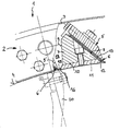
- a knife ring cutter 1 comprises a knife ring 2 which is fixedly arranged on an axis, not shown in detail here.
- the knife ring comprises knife-carrying elements 5 arranged in the area of the outer circumference 4.
- a knife-bearing element 5 each comprises a cutting knife 6, which is arranged on a knife web 7.
- the cutting knife 6 is arranged on a circumferential side surface 8 of the knife bar 7.
- the side surface 9 opposite this side surface 8, which in the circumferential direction is opposite the side surface 8 in the opposite direction is designed as a smooth surface.
- a wear plate 11 is arranged on the surface 10 of the knife bar 7 which is directed toward the axis (not shown here).
- the wear plate 11 has several tasks. It supports on the one hand the end region 12 of the blade 13 of the cutting knife, and on the other hand against wear on the knife web 7.
- the wear plate 11 in this embodiment is extended in the direction of the side face 9, so that it is above the knife web 7 in the direction of the neighboring knife-carrying Element 5 'protrudes.
- the extended wear plate 11 thus forms a smooth further projection 15, which adjoins the side surface 9, but in such a way that there is no smooth transition but an offset.
- the wear plate 11 and the knife bar 7 can be made from different materials, the wear plate 11 being made from a wear-resistant material.
- a chip exit slot 16 is in each case formed between two adjacent knife elements 5 and 5 'directly by the cutting knife 6' of the one knife-bearing element 5 'and the wear plate 11 or the projection 15 of the other adjacent knife-bearing element.
- the chip exit channel 17 into the housing 3, in which the knife ring is arranged, is formed by the cutting knife 6 'of the knife-bearing element 5' and the surface 19 of the knife-bearing element 5.
- the design of the chip exit channels 17 with their smooth side walls offers the advantage that the chip removal is not disturbed by outstanding elements and blockages and thus a backflow into the inside of the knife ring 2 are avoided.
- the projection 15 of the wear plate 11 is free of openings. It also has a straight end edge. In the present case, it is completely smooth and flat.
Landscapes
- Engineering & Computer Science (AREA)
- Life Sciences & Earth Sciences (AREA)
- Manufacturing & Machinery (AREA)
- Mechanical Engineering (AREA)
- Wood Science & Technology (AREA)
- Forests & Forestry (AREA)
- Debarking, Splitting, And Disintegration Of Timber (AREA)
Applications Claiming Priority (2)
| Application Number | Priority Date | Filing Date | Title |
|---|---|---|---|
| DE4428615 | 1994-08-12 | ||
| DE4428615 | 1994-08-12 |
Publications (1)
| Publication Number | Publication Date |
|---|---|
| EP0705668A1 true EP0705668A1 (fr) | 1996-04-10 |
Family
ID=6525558
Family Applications (1)
| Application Number | Title | Priority Date | Filing Date |
|---|---|---|---|
| EP95107833A Withdrawn EP0705668A1 (fr) | 1994-08-12 | 1995-05-23 | Déchiqueteuse à lames-couronne |
Country Status (1)
| Country | Link |
|---|---|
| EP (1) | EP0705668A1 (fr) |
Cited By (3)
| Publication number | Priority date | Publication date | Assignee | Title |
|---|---|---|---|---|
| EP0744257A3 (fr) * | 1995-05-23 | 1997-06-11 | Maier Zerkleinerungstech Gmbh | Déchiqueteuse pour coupeaux de bois |
| AT406132B (de) * | 1998-05-28 | 2000-02-25 | Boehler Miller Messer Und Saeg | Anordnung eines einweg-kamm-messers in einer messerwalze |
| WO1999059784A3 (fr) * | 1998-05-16 | 2000-04-06 | Maier Zerkleinerungstech Gmbh | Systeme d'enlevement de copeaux a lames en anneau |
Citations (9)
| Publication number | Priority date | Publication date | Assignee | Title |
|---|---|---|---|---|
| DE1199477B (de) * | 1964-06-06 | 1965-08-26 | Condux Werk | Maschine zum Zerspanen, insbesondere von Holz |
| DE2318731A1 (de) * | 1973-04-13 | 1974-10-24 | Maier Kg Maschf B | Trommelartiger messerkorb mit auswechselbaren messerpaketen |
| DE2360297A1 (de) * | 1973-12-04 | 1975-06-05 | Paul A Dr Ing Kirsten | Messerschnellwechsel fuer messerringzerspaner |
| DE2410176A1 (de) | 1974-03-04 | 1975-09-18 | Paul A Dr Ing Kirsten | Luftfuehrungen in messerring-spanern insbesondere fuer hackschnitzel |
| DE2628764A1 (de) * | 1976-06-26 | 1977-12-29 | Kloeckner Gmbh & Co Geb | Messerbefestigung in messerring-zerspanern fuer hackschnitzel |
| DE3146861A1 (de) * | 1981-11-26 | 1983-06-01 | Hombak Maschinenfabrik Gmbh & Co Kg, 6550 Bad Kreuznach | Verschleissschuh fuer einen messerringzerspaner |
| US4972888A (en) * | 1989-11-14 | 1990-11-27 | Acrowood Corporation | Blade-carrying drum assembly for chip slicing machines |
| EP0481952A1 (fr) * | 1990-10-17 | 1992-04-22 | BÖHLER YBBSTALWERKE G.m.b.H. | Pièce soumise à l'usure remplaçable |
| DE9206975U1 (de) * | 1991-05-23 | 1992-09-17 | Globus S.r.l., Galliate, Novara | Zerspanungsmaschine für Holz und holzähnliches Material |
-
1995
- 1995-05-23 EP EP95107833A patent/EP0705668A1/fr not_active Withdrawn
Patent Citations (9)
| Publication number | Priority date | Publication date | Assignee | Title |
|---|---|---|---|---|
| DE1199477B (de) * | 1964-06-06 | 1965-08-26 | Condux Werk | Maschine zum Zerspanen, insbesondere von Holz |
| DE2318731A1 (de) * | 1973-04-13 | 1974-10-24 | Maier Kg Maschf B | Trommelartiger messerkorb mit auswechselbaren messerpaketen |
| DE2360297A1 (de) * | 1973-12-04 | 1975-06-05 | Paul A Dr Ing Kirsten | Messerschnellwechsel fuer messerringzerspaner |
| DE2410176A1 (de) | 1974-03-04 | 1975-09-18 | Paul A Dr Ing Kirsten | Luftfuehrungen in messerring-spanern insbesondere fuer hackschnitzel |
| DE2628764A1 (de) * | 1976-06-26 | 1977-12-29 | Kloeckner Gmbh & Co Geb | Messerbefestigung in messerring-zerspanern fuer hackschnitzel |
| DE3146861A1 (de) * | 1981-11-26 | 1983-06-01 | Hombak Maschinenfabrik Gmbh & Co Kg, 6550 Bad Kreuznach | Verschleissschuh fuer einen messerringzerspaner |
| US4972888A (en) * | 1989-11-14 | 1990-11-27 | Acrowood Corporation | Blade-carrying drum assembly for chip slicing machines |
| EP0481952A1 (fr) * | 1990-10-17 | 1992-04-22 | BÖHLER YBBSTALWERKE G.m.b.H. | Pièce soumise à l'usure remplaçable |
| DE9206975U1 (de) * | 1991-05-23 | 1992-09-17 | Globus S.r.l., Galliate, Novara | Zerspanungsmaschine für Holz und holzähnliches Material |
Cited By (3)
| Publication number | Priority date | Publication date | Assignee | Title |
|---|---|---|---|---|
| EP0744257A3 (fr) * | 1995-05-23 | 1997-06-11 | Maier Zerkleinerungstech Gmbh | Déchiqueteuse pour coupeaux de bois |
| WO1999059784A3 (fr) * | 1998-05-16 | 2000-04-06 | Maier Zerkleinerungstech Gmbh | Systeme d'enlevement de copeaux a lames en anneau |
| AT406132B (de) * | 1998-05-28 | 2000-02-25 | Boehler Miller Messer Und Saeg | Anordnung eines einweg-kamm-messers in einer messerwalze |
Similar Documents
| Publication | Publication Date | Title |
|---|---|---|
| EP2488693B1 (fr) | Pulpeur | |
| DE10215833A1 (de) | Schneidkörper mit einem Schlegel | |
| DE2405702C3 (de) | Stofflöser zum Herstellen einer pumpfähigen Suspension aus trockenen Papierrohstoffen | |
| EP0744257B1 (fr) | Déchiqueteuse pour coupeaux de bois | |
| EP0705668A1 (fr) | Déchiqueteuse à lames-couronne | |
| DE3925098C2 (de) | Vorrichtung zum Zerkleinern von Material, sogenannter Turboseparator | |
| EP1679403B1 (fr) | Pulpeur pour désintégrer et mettre en suspension des matériaux pour pâte à papier | |
| DE69814362T2 (de) | Zuführelement für fasermaterial | |
| DE19921597C1 (de) | Messerring-Zerspaner zum Zerspanen von Hackschnitzeln | |
| EP3381563B1 (fr) | Déchiqueteuse | |
| EP0367255B1 (fr) | Machine à déchiqueter le bois en coupeaux | |
| DE2618254A1 (de) | Messertrommel, insbesondere fuer hackmaschinen zur zerkleinerung von hoelzern und abfaellen | |
| EP0807500A2 (fr) | Déchiqueteuse pour coupeaux de bois | |
| WO2002040166A2 (fr) | Broyeur centrifuge a deux chambres | |
| DE102009005929B4 (de) | Schneidwerk, insbesondere für einen Fleischwolf | |
| EP1574615A1 (fr) | Raffineur et garniture pour raffineur de pâte à papier | |
| EP0175313B1 (fr) | Dispositif pour le broyage de déchets | |
| DE2457403A1 (de) | Vorrichtung zum zerspanen von material, insbesondere von holz | |
| DE2651569A1 (de) | Schneidvorrichtung zum zerkleinern von gartenfruechten, sogenannter zwiebelschneider | |
| DE8913448U1 (de) | Zerkleinerungsmaschine für faser- oder streifenförmiges Material | |
| DE2437202A1 (de) | Zufuehrvorrichtung | |
| DE29718512U1 (de) | Zerkleinerungsvorrichtung | |
| DE202005010055U1 (de) | Paddelmesser für eine Häckslervorrichtung sowie Häckslervorrichtung mit einem solchen Paddelmesser | |
| EP0992326B1 (fr) | Elément d'usure pour déchiqueteuse à couronne rotative | |
| EP0956935B1 (fr) | Déchiqueteuse à lames-couronne |
Legal Events
| Date | Code | Title | Description |
|---|---|---|---|
| PUAI | Public reference made under article 153(3) epc to a published international application that has entered the european phase |
Free format text: ORIGINAL CODE: 0009012 |
|
| AK | Designated contracting states |
Kind code of ref document: A1 Designated state(s): BE DE FR IT |
|
| STAA | Information on the status of an ep patent application or granted ep patent |
Free format text: STATUS: THE APPLICATION IS DEEMED TO BE WITHDRAWN |
|
| 18D | Application deemed to be withdrawn |
Effective date: 19961011 |