EP0705716A1 - Kappe für ein Schreibgerät - Google Patents
Kappe für ein Schreibgerät Download PDFInfo
- Publication number
- EP0705716A1 EP0705716A1 EP95100516A EP95100516A EP0705716A1 EP 0705716 A1 EP0705716 A1 EP 0705716A1 EP 95100516 A EP95100516 A EP 95100516A EP 95100516 A EP95100516 A EP 95100516A EP 0705716 A1 EP0705716 A1 EP 0705716A1
- Authority
- EP
- European Patent Office
- Prior art keywords
- cap
- cylindrical shell
- elastic member
- writing tool
- outside
- Prior art date
- Legal status (The legal status is an assumption and is not a legal conclusion. Google has not performed a legal analysis and makes no representation as to the accuracy of the status listed.)
- Granted
Links
- 230000002093 peripheral effect Effects 0.000 claims abstract description 10
- 239000000463 material Substances 0.000 claims abstract description 8
- 238000003780 insertion Methods 0.000 description 6
- 230000037431 insertion Effects 0.000 description 6
- 230000000694 effects Effects 0.000 description 2
- 238000000465 moulding Methods 0.000 description 2
- 230000003405 preventing effect Effects 0.000 description 2
- 239000011347 resin Substances 0.000 description 2
- 229920005989 resin Polymers 0.000 description 2
- 238000000071 blow moulding Methods 0.000 description 1
- 230000003292 diminished effect Effects 0.000 description 1
- 239000013013 elastic material Substances 0.000 description 1
- 238000001746 injection moulding Methods 0.000 description 1
- 230000004048 modification Effects 0.000 description 1
- 238000012986 modification Methods 0.000 description 1
Images

Classifications
-
- B—PERFORMING OPERATIONS; TRANSPORTING
- B43—WRITING OR DRAWING IMPLEMENTS; BUREAU ACCESSORIES
- B43K—IMPLEMENTS FOR WRITING OR DRAWING
- B43K23/00—Holders or connectors for writing implements; Means for protecting the writing-points
- B43K23/08—Protecting means, e.g. caps
- B43K23/12—Protecting means, e.g. caps for pens
-
- B—PERFORMING OPERATIONS; TRANSPORTING
- B43—WRITING OR DRAWING IMPLEMENTS; BUREAU ACCESSORIES
- B43K—IMPLEMENTS FOR WRITING OR DRAWING
- B43K23/00—Holders or connectors for writing implements; Means for protecting the writing-points
- B43K23/008—Holders comprising finger grips
-
- B—PERFORMING OPERATIONS; TRANSPORTING
- B43—WRITING OR DRAWING IMPLEMENTS; BUREAU ACCESSORIES
- B43K—IMPLEMENTS FOR WRITING OR DRAWING
- B43K23/00—Holders or connectors for writing implements; Means for protecting the writing-points
- B43K23/08—Protecting means, e.g. caps
- B43K23/12—Protecting means, e.g. caps for pens
- B43K23/122—Protecting means, e.g. caps for pens with means for preventing choking
- B43K23/124—Protecting means, e.g. caps for pens with means for preventing choking comprising an air passage
-
- B—PERFORMING OPERATIONS; TRANSPORTING
- B43—WRITING OR DRAWING IMPLEMENTS; BUREAU ACCESSORIES
- B43K—IMPLEMENTS FOR WRITING OR DRAWING
- B43K23/00—Holders or connectors for writing implements; Means for protecting the writing-points
- B43K23/08—Protecting means, e.g. caps
- B43K23/12—Protecting means, e.g. caps for pens
- B43K23/126—Protecting means, e.g. caps for pens with clips
Definitions
- the present invention relates to a cap to be fitted onto a pen point side of a writing tool such as a ball-point pen or a signing pen.
- the invention is concerned with an improvement of a cap to be fitted onto a writing tool provided with an elastic member, or a so-called non-slip means, of a different material from the material of the cap or a cylindrical shell, the non-slip means being mounted on the grip portion of the cylindrical shell, to improve both non-slip characteristic and grasping feel during use of the writing tool.
- the non-slip means is mainly formed of an elastic material such as rubber which is relatively soft and exhibits a slip preventing effect, while the cap, like the cylindrical shell, is formed of a hard resin. Further, the inner surface (inside diameter) of the cap is formed in a shape conforming to the outer surface shape (outside diameter) of the grip portion of the cylindrical shell on which the cap is to be fitted, without permitting a large play relative to the outside of the cylindrical shell grip portion and so that the cap can be mounted and removed relative to the front-end grip portion including the pen point.
- the cap contacts the non-slip means over a large surface and the force of contact thereof with the elastic member becomes large to the extent that the mounting and removal of the cap can no longer be effected smoothly. Since the mounting and removal of the cap are performed forcibly, the non-slip means is damaged in a short period and hence its slip preventing effect is deteriorated.
- the present invention has been accomplished in view of such conventional circumstances and it is the object of the invention to provide a cap for a writing tool provided with a non-slip means which cap can reduce the force of contact with the outside of a cylindrical shell having an elastic member and can thereby effect smooth mounting and removal of the cap.
- a cap for a writing tool having on the outside of a cylindrical shell an elastic member of a different material from the material of the cap, the cap having a plurality of longitudinal ribs formed on the inner peripheral surface of the cap and which ribs extend along the cylindrical shell. End portions of the said longitudinal ribs on the opening edge side of the cap may each be cut in the form of an arch.
- the cap since longitudinal ribs are formed in the inner peripheral surface of the cap, the cap is fitted on the cylindrical shell in the state of linear contact in the direction of insertion with respect to the elastic member provided on the outside of the cylindrical shell, whereby the contact force is greatly reduced.
- Fig. 1 is a front view in longitudinal section, showing a cap as fitted on a cylindrical shell.
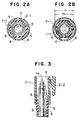
- Figs. 2(a) and 2(b) are cross-sectional views taken on line II-II in Fig.1.
- Fig. 3 is an enlarged, partial, sectional view.
- Fig.1 illustrates a ball-point pen as an example of writing tool.
- the numeral 1 denotes a cylindrical shell
- numeral 2 denotes a cap which is fitted removably on a pen point 1a side of the cylindrical shell 1
- numeral 3 denotes a spare ink tube loaded into the cylindrical shell 1.
- the inner peripheral surface of the cap 2 are formed a plurality of longitudinal ribs 4 extending along the cylindrical shell to minimize the force of contact with an elastic member 5 which is mounted on the pen point 1a side of the cylindrical shell 1.
- the cylindrical shell 1 and the cap 2 are integrally molded products obtained, for example, by blow molding or injection molding.
- the cylindrical shell 1 comprises a cylindrical front portion 1-1 which serves as a grip portion during use of the ball-point pen and a cylindrical rear portion 1-2 which is removably connected threadedly with the rear end of the Front portion 1-1.
- the outside of the cylindrical front portion 1-1 is formed with a recess 6 for mounting of the elastic member in such a manner that the elastic member cannot move along the cylindrical shell.
- a ring-like projection 9 On the outside of the cylindrical shell 1 is formed a ring-like projection 9 in a position between the recess 6 and the pen point 1 so as to attain close engagement with a ring-like projection 8 formed on the inner peripheral surface of the cap 2 as will be described later.
- the cap 2 has a cap portion 2-1 and a clip 2-2 formed integrally outside the cap portion, the cap portion 2-1 being formed by molding in a length capable of covering the whole of the cylindrical front portion 1-1 including the pen point 1a and so as to have an inner surface shape of a size larger (an inside diameter not causing contact with the elastic member 5) than the normal size.
- On the inner peripheral surface of the cap portion 2-1 are formed longitudinal ribs 4 extending along the cylindrical shell, namely, in the direction of insertion and removal of the cap 2, from the portion near the opening edge of the cap. Further, on the inner end side of the longitudinal ribs 4, a ring-like projection 8 is formed on the inner peripheral surface of the cap portion.
- the longitudinal ribs 4 function to reduce the area of contact of the cap portion 2-1 with the elastic member 5 so that the cap portion 2-1 of the cap 2 can be smoothly fitted on and pulled out from the cylindrical front portion 1-1 of the cylindrical shell 1.
- Those ribs are formed integrally at the time of molding of the cap 2 in several, say, 3 to 6 (6 in the illustrated embodiment), positions in the circumferential direction from near the opening edge of the cap portion 2-1.
- End portions of the longitudinal ribs 4 located on the opening edge side of the cap portion 2-1 of the cap 2 are each cut largely in the shape of an arch, whereby the end portions are prevented from being caught on the elastic member 5 when the cap is fitted on the cylindrical shell 1 (see Fig.3).
- a virtual inside diameter r1 connecting the apexes of the longitudinal ribs 4 in the circumferential direction may be set a size larger than the outside diameter r2 of the elastic member 5 (r1 > r2).
- the contact thereof with the elastic member 5 formed of a soft resin, rubber or the like is done as a linear contact in the direction of insertion and removal of the cap through the longitudinal ribs 4 formed on the inner peripheral surface of the cap portion 2-1. Consequently, it is possible to reduce the contact area, that is, reduce the contact force greatly, whereby the mounting and removal of the cap can be done smoothly.
- the elastic member 5 is provided on the pen point 1a side outside the cylindrical shell 1, there may be adopted the form of a rudder shaft with the elastic member 5 provided not only on the pen point 1a side but also over the whole of the outside of the cylindrical shell 1.
- the cap for a writing tool according to the present invention is constructed as above, there can be attained the following functions and effects.
- the contact thereof with the elastic member provided outside the cylindrical shell is done as a linear contact in the direction of insertion and removal of the cap through the longitudinal ribs formed on the inner peripheral surface of the cap portion, whereby the force of contact with the elastic member can be reduced to a great extent.
- the cap of the present invention since it comes into contact with the elastic member provided outside the cylindrical shell in the state of a linear contact extending along the cylindrical shell (in the direction of insertion and removal of the cap), the contact area is greatly reduced and hence the contact force at the time of insertion or removal of the cap is diminished, thereby permitting smooth mounting and removal of the cap and attaining improvement in handlability of the cap. This is very convenient.
Landscapes
- Pens And Brushes (AREA)
- Mechanical Pencils And Projecting And Retracting Systems Therefor, And Multi-System Writing Instruments (AREA)
Applications Claiming Priority (2)
| Application Number | Priority Date | Filing Date | Title |
|---|---|---|---|
| JP6238856A JP2906391B2 (ja) | 1994-10-03 | 1994-10-03 | 筆記具用キャップ |
| JP238856/94 | 1994-10-03 |
Publications (2)
| Publication Number | Publication Date |
|---|---|
| EP0705716A1 true EP0705716A1 (de) | 1996-04-10 |
| EP0705716B1 EP0705716B1 (de) | 1997-11-19 |
Family
ID=17036284
Family Applications (1)
| Application Number | Title | Priority Date | Filing Date |
|---|---|---|---|
| EP95100516A Expired - Lifetime EP0705716B1 (de) | 1994-10-03 | 1995-01-17 | Kappe für ein Schreibgerät |
Country Status (11)
| Country | Link |
|---|---|
| US (1) | US5911534A (de) |
| EP (1) | EP0705716B1 (de) |
| JP (1) | JP2906391B2 (de) |
| KR (1) | KR100335577B1 (de) |
| CN (1) | CN1078142C (de) |
| CA (1) | CA2141248C (de) |
| DE (2) | DE69501074D1 (de) |
| MY (1) | MY112793A (de) |
| NO (1) | NO305588B1 (de) |
| SG (1) | SG34276A1 (de) |
| TW (1) | TW284724B (de) |
Cited By (1)
| Publication number | Priority date | Publication date | Assignee | Title |
|---|---|---|---|---|
| WO2000059737A1 (en) * | 1999-04-05 | 2000-10-12 | Berol Corporation | Improvements in or relating to marking instruments |
Families Citing this family (18)
| Publication number | Priority date | Publication date | Assignee | Title |
|---|---|---|---|---|
| AU147380S (en) | 2001-05-30 | 2002-04-17 | Pentel Kk | A cap for a writing instrument |
| AU147379S (en) | 2001-05-30 | 2002-04-17 | Pentel Kk | A cap for a writing instrument |
| USD464676S1 (en) | 2001-09-25 | 2002-10-22 | Bic Corporation | Grip element |
| US6485211B1 (en) | 2001-09-25 | 2002-11-26 | Bic Corporation | Easily assembled grip element |
| US20070066396A1 (en) | 2002-04-05 | 2007-03-22 | Denise Chapman Weston | Retail methods for providing an interactive product to a consumer |
| US20040126556A1 (en) * | 2002-12-27 | 2004-07-01 | Nowak Michael T. | Grip element |
| USD500791S1 (en) | 2003-10-23 | 2005-01-11 | Societe Bic | Writing instrument |
| USD549778S1 (en) | 2006-05-31 | 2007-08-28 | Staples The Office Superstore Llc | Pen |
| USD549775S1 (en) | 2006-05-31 | 2007-08-28 | Staples The Office Superstore Llc | Pen |
| USD576675S1 (en) | 2006-11-29 | 2008-09-09 | Staples The Office Superstore Llc | Pen |
| FR2939079B1 (fr) * | 2008-11-28 | 2011-08-19 | Bic Soc | Instrument d'ecriture et capuchon pour un instrument d'ecriture |
| JP5298846B2 (ja) * | 2008-12-26 | 2013-09-25 | ぺんてる株式会社 | 軸筒 |
| JP5525409B2 (ja) * | 2010-10-12 | 2014-06-18 | ミクロ株式会社 | 筆記具 |
| CN102795025B (zh) * | 2011-05-27 | 2016-02-03 | 斑马株式会社 | 带盖书写工具 |
| JP6392298B2 (ja) * | 2011-12-09 | 2018-09-19 | 三菱鉛筆株式会社 | 消去部材を備えた筆記具 |
| CN103303034A (zh) * | 2012-03-14 | 2013-09-18 | 南通迅翔自动化设备有限公司 | 一种通用笔帽 |
| EP2708372A1 (de) * | 2012-09-18 | 2014-03-19 | The Swatch Group Research and Development Ltd. | Schreibinstrument |
| US12593906B2 (en) * | 2020-05-04 | 2026-04-07 | Brandi Theodette Weintraub | Caps for cosmetic implements |
Citations (9)
| Publication number | Priority date | Publication date | Assignee | Title |
|---|---|---|---|---|
| US2312069A (en) * | 1942-02-25 | 1943-02-23 | John G Baumgartner | Protector cap |
| FR1193771A (de) * | 1959-11-04 | |||
| DE2013582A1 (de) * | 1970-03-21 | 1971-10-14 | Merz & Krell, 6101 Groß Bieberau | Schreibgerat, insbesondere Füllfeder halter |
| FR2265552A1 (de) * | 1974-03-27 | 1975-10-24 | Mutschler Philipp | |
| US4123179A (en) * | 1977-01-05 | 1978-10-31 | Pacheco Nelly M | Orthopedic finger piece for writing instruments |
| WO1980000557A1 (fr) * | 1978-09-11 | 1980-04-03 | Du Pont | Instrument a ecrire |
| DE8714810U1 (de) * | 1987-11-03 | 1988-01-14 | Hermann Böhler GmbH, 6915 Dossenheim | Schreibgerät, insbesondere Füllfederhalter, mit Hartkunststoffmundstück, das mit einem Antirutschprofil versehen ist |
| US5154526A (en) * | 1991-12-20 | 1992-10-13 | J. S. Staedtler Gmbh & Co. | Capillary pen cover |
| WO1993009961A1 (en) * | 1991-11-13 | 1993-05-27 | Bic Corporation | A cap for writing and marking instruments |
Family Cites Families (10)
| Publication number | Priority date | Publication date | Assignee | Title |
|---|---|---|---|---|
| GB782159A (en) * | 1954-04-15 | 1957-09-04 | Mabie Todd & Co Ltd | Improvements in writing instruments |
| DE1253614B (de) * | 1960-01-28 | 1967-11-02 | Montblanc Simplo Gmbh | Verschlussstueck fuer ein Minenroehrchen eines Kugelschreibers |
| DE2157175A1 (de) * | 1971-11-18 | 1973-05-24 | Montblanc Simplo Gmbh | Schreibgeraet mit einem am schaftvorderteil ausgebildeten rutschfesten griffstueck |
| DE3010862A1 (de) * | 1980-03-21 | 1981-10-01 | Otto 6900 Heidelberg Mutschler | Aufnahme- und haltebox fuer tuschefueller |
| DE3644978A1 (de) * | 1986-11-27 | 1988-06-09 | Staedtler Fa J S | Kappe fuer schreib- und auftragsgeraete |
| JPH022632U (de) * | 1988-06-18 | 1990-01-09 | ||
| JP2522377Y2 (ja) * | 1990-07-26 | 1997-01-16 | 象印マホービン株式会社 | エアーポットのエアーポンプの吸気弁 |
| JPH0593880U (ja) * | 1992-05-29 | 1993-12-21 | セーラー万年筆株式会社 | 筆記具用キャップ |
| JPH0635018A (ja) * | 1992-07-13 | 1994-02-10 | Sony Corp | 光源一体型波長変換素子 |
| JP2581473Y2 (ja) * | 1993-03-31 | 1998-09-21 | ぺんてる株式会社 | 筆記具のキャップ |
-
1994
- 1994-10-03 JP JP6238856A patent/JP2906391B2/ja not_active Expired - Fee Related
- 1994-12-13 TW TW083111575A patent/TW284724B/zh active
- 1994-12-19 KR KR1019940035033A patent/KR100335577B1/ko not_active Expired - Fee Related
-
1995
- 1995-01-09 MY MYPI95000044A patent/MY112793A/en unknown
- 1995-01-16 CN CN95101405A patent/CN1078142C/zh not_active Expired - Fee Related
- 1995-01-17 DE DE69501074A patent/DE69501074D1/de not_active Expired - Fee Related
- 1995-01-17 DE DE69501074T patent/DE69501074T4/de not_active Expired - Lifetime
- 1995-01-17 EP EP95100516A patent/EP0705716B1/de not_active Expired - Lifetime
- 1995-01-18 NO NO950182A patent/NO305588B1/no not_active IP Right Cessation
- 1995-01-25 CA CA002141248A patent/CA2141248C/en not_active Expired - Fee Related
- 1995-10-03 SG SG1995001471A patent/SG34276A1/en unknown
-
1996
- 1996-11-18 US US08/751,716 patent/US5911534A/en not_active Expired - Lifetime
Patent Citations (9)
| Publication number | Priority date | Publication date | Assignee | Title |
|---|---|---|---|---|
| FR1193771A (de) * | 1959-11-04 | |||
| US2312069A (en) * | 1942-02-25 | 1943-02-23 | John G Baumgartner | Protector cap |
| DE2013582A1 (de) * | 1970-03-21 | 1971-10-14 | Merz & Krell, 6101 Groß Bieberau | Schreibgerat, insbesondere Füllfeder halter |
| FR2265552A1 (de) * | 1974-03-27 | 1975-10-24 | Mutschler Philipp | |
| US4123179A (en) * | 1977-01-05 | 1978-10-31 | Pacheco Nelly M | Orthopedic finger piece for writing instruments |
| WO1980000557A1 (fr) * | 1978-09-11 | 1980-04-03 | Du Pont | Instrument a ecrire |
| DE8714810U1 (de) * | 1987-11-03 | 1988-01-14 | Hermann Böhler GmbH, 6915 Dossenheim | Schreibgerät, insbesondere Füllfederhalter, mit Hartkunststoffmundstück, das mit einem Antirutschprofil versehen ist |
| WO1993009961A1 (en) * | 1991-11-13 | 1993-05-27 | Bic Corporation | A cap for writing and marking instruments |
| US5154526A (en) * | 1991-12-20 | 1992-10-13 | J. S. Staedtler Gmbh & Co. | Capillary pen cover |
Cited By (3)
| Publication number | Priority date | Publication date | Assignee | Title |
|---|---|---|---|---|
| WO2000059737A1 (en) * | 1999-04-05 | 2000-10-12 | Berol Corporation | Improvements in or relating to marking instruments |
| GB2366767A (en) * | 1999-04-05 | 2002-03-20 | Berol Corp | Improvements in or relating to marking instruments |
| GB2366767B (en) * | 1999-04-05 | 2003-03-19 | Berol Corp | Improvements in or relating to marking instruments |
Also Published As
| Publication number | Publication date |
|---|---|
| CA2141248C (en) | 2004-08-31 |
| NO305588B1 (no) | 1999-06-28 |
| DE69501074D1 (de) | 1998-01-02 |
| JP2906391B2 (ja) | 1999-06-21 |
| CN1119995A (zh) | 1996-04-10 |
| US5911534A (en) | 1999-06-15 |
| HK1004776A1 (en) | 1998-12-04 |
| TW284724B (de) | 1996-09-01 |
| CN1078142C (zh) | 2002-01-23 |
| JPH08104097A (ja) | 1996-04-23 |
| CA2141248A1 (en) | 1996-04-04 |
| EP0705716B1 (de) | 1997-11-19 |
| DE69501074T4 (de) | 1998-12-24 |
| DE69501074T2 (de) | 1998-03-12 |
| KR100335577B1 (ko) | 2002-08-28 |
| SG34276A1 (en) | 1996-12-06 |
| MY112793A (en) | 2001-09-29 |
| NO950182L (no) | 1996-04-09 |
| NO950182D0 (no) | 1995-01-18 |
Similar Documents
| Publication | Publication Date | Title |
|---|---|---|
| EP0705716A1 (de) | Kappe für ein Schreibgerät | |
| US6206595B1 (en) | Writing utensil | |
| US5716152A (en) | Writing tool | |
| JP2545330Y2 (ja) | 筆記具 | |
| EP1071563A1 (de) | Schreibgerät mit handgreifvorrichtung | |
| JP3817719B2 (ja) | 筆記具のグリップ | |
| HK1004776B (en) | Cap for writing tool | |
| US20070154253A1 (en) | Writing instrument | |
| US20040086316A1 (en) | Writing implements | |
| EP0456831A1 (de) | Kappe | |
| EP0850784A2 (de) | Behälter mit Mitteln zum selektiven Aus- und Einziehen von einem im wesentlichen stiftförmigen Gegenstand | |
| JP4282352B2 (ja) | ノック式筆記具のノック部 | |
| JPH08501999A (ja) | インク カートリッヂ用ベント プラグ | |
| US5067839A (en) | Stylo pen tip and auxiliary removing tool | |
| JPH11334273A (ja) | 筆記具の把持部材取り付け構造 | |
| JP3348179B2 (ja) | 筆記具における把持部構造 | |
| JP2607455Y2 (ja) | 筆記具に於ける滑り止め部材 | |
| JP3611221B2 (ja) | 筆記具の口先具 | |
| JPH10203077A (ja) | 弾性グリップ付き筆記具軸 | |
| JP2000043477A5 (de) | ||
| JP3918081B2 (ja) | 筆記具 | |
| JP2001150870A (ja) | 筆記具のキャップ装着構造 | |
| JP3873394B2 (ja) | シャ−プペンシル | |
| JP3209055B2 (ja) | 打込機のノーズキャップ | |
| JP4851277B2 (ja) | 筆記具 |
Legal Events
| Date | Code | Title | Description |
|---|---|---|---|
| PUAI | Public reference made under article 153(3) epc to a published international application that has entered the european phase |
Free format text: ORIGINAL CODE: 0009012 |
|
| AK | Designated contracting states |
Kind code of ref document: A1 Designated state(s): DE FR GB IT |
|
| 17P | Request for examination filed |
Effective date: 19960610 |
|
| 17Q | First examination report despatched |
Effective date: 19960709 |
|
| GRAG | Despatch of communication of intention to grant |
Free format text: ORIGINAL CODE: EPIDOS AGRA |
|
| GRAH | Despatch of communication of intention to grant a patent |
Free format text: ORIGINAL CODE: EPIDOS IGRA |
|
| GRAH | Despatch of communication of intention to grant a patent |
Free format text: ORIGINAL CODE: EPIDOS IGRA |
|
| GRAA | (expected) grant |
Free format text: ORIGINAL CODE: 0009210 |
|
| ITF | It: translation for a ep patent filed | ||
| AK | Designated contracting states |
Kind code of ref document: B1 Designated state(s): DE FR GB IT |
|
| REF | Corresponds to: |
Ref document number: 69501074 Country of ref document: DE Date of ref document: 19980102 |
|
| ET | Fr: translation filed | ||
| PLBE | No opposition filed within time limit |
Free format text: ORIGINAL CODE: 0009261 |
|
| STAA | Information on the status of an ep patent application or granted ep patent |
Free format text: STATUS: NO OPPOSITION FILED WITHIN TIME LIMIT |
|
| 26N | No opposition filed | ||
| REG | Reference to a national code |
Ref country code: GB Ref legal event code: IF02 |
|
| PGFP | Annual fee paid to national office [announced via postgrant information from national office to epo] |
Ref country code: DE Payment date: 20020113 Year of fee payment: 8 |
|
| PGFP | Annual fee paid to national office [announced via postgrant information from national office to epo] |
Ref country code: FR Payment date: 20020121 Year of fee payment: 8 |
|
| PG25 | Lapsed in a contracting state [announced via postgrant information from national office to epo] |
Ref country code: DE Free format text: LAPSE BECAUSE OF NON-PAYMENT OF DUE FEES Effective date: 20030801 |
|
| PG25 | Lapsed in a contracting state [announced via postgrant information from national office to epo] |
Ref country code: FR Free format text: LAPSE BECAUSE OF NON-PAYMENT OF DUE FEES Effective date: 20030930 |
|
| REG | Reference to a national code |
Ref country code: FR Ref legal event code: ST |
|
| PGFP | Annual fee paid to national office [announced via postgrant information from national office to epo] |
Ref country code: GB Payment date: 20031210 Year of fee payment: 10 |
|
| PG25 | Lapsed in a contracting state [announced via postgrant information from national office to epo] |
Ref country code: IT Free format text: LAPSE BECAUSE OF NON-PAYMENT OF DUE FEES;WARNING: LAPSES OF ITALIAN PATENTS WITH EFFECTIVE DATE BEFORE 2007 MAY HAVE OCCURRED AT ANY TIME BEFORE 2007. THE CORRECT EFFECTIVE DATE MAY BE DIFFERENT FROM THE ONE RECORDED. Effective date: 20050117 Ref country code: GB Free format text: LAPSE BECAUSE OF NON-PAYMENT OF DUE FEES Effective date: 20050117 |
|
| GBPC | Gb: european patent ceased through non-payment of renewal fee |
Effective date: 20050117 |