EP0705730B1 - Phare avec feux de route et codes pour véhicule - Google Patents
Phare avec feux de route et codes pour véhicule Download PDFInfo
- Publication number
- EP0705730B1 EP0705730B1 EP95114689A EP95114689A EP0705730B1 EP 0705730 B1 EP0705730 B1 EP 0705730B1 EP 95114689 A EP95114689 A EP 95114689A EP 95114689 A EP95114689 A EP 95114689A EP 0705730 B1 EP0705730 B1 EP 0705730B1
- Authority
- EP
- European Patent Office
- Prior art keywords
- light source
- reflector
- headlight according
- headlight
- cap
- Prior art date
- Legal status (The legal status is an assumption and is not a legal conclusion. Google has not performed a legal analysis and makes no representation as to the accuracy of the status listed.)
- Expired - Lifetime
Links
Images




Classifications
-
- B—PERFORMING OPERATIONS; TRANSPORTING
- B60—VEHICLES IN GENERAL
- B60Q—ARRANGEMENT OF SIGNALLING OR LIGHTING DEVICES, THE MOUNTING OR SUPPORTING THEREOF OR CIRCUITS THEREFOR, FOR VEHICLES IN GENERAL
- B60Q1/00—Arrangement of optical signalling or lighting devices, the mounting or supporting thereof or circuits therefor
- B60Q1/02—Arrangement of optical signalling or lighting devices, the mounting or supporting thereof or circuits therefor the devices being primarily intended to illuminate the way ahead or to illuminate other areas of way or environments
- B60Q1/04—Arrangement of optical signalling or lighting devices, the mounting or supporting thereof or circuits therefor the devices being primarily intended to illuminate the way ahead or to illuminate other areas of way or environments the devices being headlights
- B60Q1/14—Arrangement of optical signalling or lighting devices, the mounting or supporting thereof or circuits therefor the devices being primarily intended to illuminate the way ahead or to illuminate other areas of way or environments the devices being headlights having dimming means
- B60Q1/1415—Dimming circuits
-
- F—MECHANICAL ENGINEERING; LIGHTING; HEATING; WEAPONS; BLASTING
- F21—LIGHTING
- F21S—NON-PORTABLE LIGHTING DEVICES; SYSTEMS THEREOF; VEHICLE LIGHTING DEVICES SPECIALLY ADAPTED FOR VEHICLE EXTERIORS
- F21S41/00—Illuminating devices specially adapted for vehicle exteriors, e.g. headlamps
- F21S41/60—Illuminating devices specially adapted for vehicle exteriors, e.g. headlamps characterised by a variable light distribution
- F21S41/65—Illuminating devices specially adapted for vehicle exteriors, e.g. headlamps characterised by a variable light distribution by acting on light sources
- F21S41/657—Illuminating devices specially adapted for vehicle exteriors, e.g. headlamps characterised by a variable light distribution by acting on light sources by moving light sources
-
- F—MECHANICAL ENGINEERING; LIGHTING; HEATING; WEAPONS; BLASTING
- F21—LIGHTING
- F21S—NON-PORTABLE LIGHTING DEVICES; SYSTEMS THEREOF; VEHICLE LIGHTING DEVICES SPECIALLY ADAPTED FOR VEHICLE EXTERIORS
- F21S41/00—Illuminating devices specially adapted for vehicle exteriors, e.g. headlamps
- F21S41/60—Illuminating devices specially adapted for vehicle exteriors, e.g. headlamps characterised by a variable light distribution
- F21S41/68—Illuminating devices specially adapted for vehicle exteriors, e.g. headlamps characterised by a variable light distribution by acting on screens
- F21S41/683—Illuminating devices specially adapted for vehicle exteriors, e.g. headlamps characterised by a variable light distribution by acting on screens by moving screens
- F21S41/692—Shields, i.e. screens not creating an image meant to be projected
-
- F—MECHANICAL ENGINEERING; LIGHTING; HEATING; WEAPONS; BLASTING
- F21—LIGHTING
- F21S—NON-PORTABLE LIGHTING DEVICES; SYSTEMS THEREOF; VEHICLE LIGHTING DEVICES SPECIALLY ADAPTED FOR VEHICLE EXTERIORS
- F21S41/00—Illuminating devices specially adapted for vehicle exteriors, e.g. headlamps
- F21S41/10—Illuminating devices specially adapted for vehicle exteriors, e.g. headlamps characterised by the light source
- F21S41/14—Illuminating devices specially adapted for vehicle exteriors, e.g. headlamps characterised by the light source characterised by the type of light source
- F21S41/17—Discharge light sources
Definitions
- the invention is based on a headlight for low beam and high beam for vehicles according to the preamble of claim 1.
- Such a headlight is known from EP-A-0595267.
- This headlight has a reflector and a light source in the form of a gas discharge lamp.
- the light source is through an actuator between a position for low beam and a position for high beam in the direction of the optical axis of the Reflector and also vertical to the optical axis movable.
- the The light-dark boundary can be generated by the reflector light emitted by the light source as a bundle of light is reflected, the light-dark boundary by the shape of the reflector having.
- EP-A-0220068 is a headlight for low beam and High beam known for vehicles, the one reflector and one Has light source in the form of a gas discharge lamp, the Reflector can be moved together with the light source.
- the Low-light limit of the low beam is generated in this Document not specified.
- the headlight according to the invention with the features according to Claim 1 has the advantage that the Shielding device ensures that the light-dark boundary of the low beam takes the required position and clearly is pronounced so that it is ensured that there is no glare oncoming traffic occurs.
- a simple formation of the shielding device is achieved by the training according to claim 2.
- the training according to claim 8 ensures that the light source is in precisely defined positions for the generation of the low beam and / or the High beam.
- the elastically deformable intermediate link according to claim 9, on the one hand, is independent of manufacturing tolerances the system at the stops safe and guaranteed also the attachment to the attacks possible vibrations.
- claims 12 and 16 are simple and only small adjustment paths between the low beam and high beam positions Shielding devices specified.
- FIG. 1 shows a headlight for Low beam and high beam for vehicles in a vertical Longitudinal section with an actuator for moving the light source according to a first embodiment
- Figure 2 a in front of the headlight arranged measuring screen, which by the Low beam emitted by the reflector in the operating position 3 is the measuring screen when lighting by the reflector in the operating position Beam emitted light beam
- Figure 4 the measuring screen when lighting through that from the headlight bundles of light emerging after passing through a diffusing screen in the low beam operating position
- FIG. 1 shows a headlight for Low beam and high beam for vehicles in a vertical Longitudinal section with an actuator for moving the light source according to a first embodiment
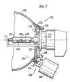
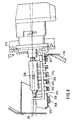
- FIG. 6 shows a detail of the headlamp with a variant of the control element for moving the light source and Figure 7 shows a section of the headlight with a second embodiment of the actuator for moving the light source, figure 8 shows a detail of the headlight according to a third Embodiment with a modified shielding device in a position for low beam, Figure 9 the headlight of Figure 8 with the shielding device in one Position for high beam, Figure 10 shows a section of the Headlamp according to a fourth embodiment a modified shielding device in one position for low beam in the view opposite the light exit direction and FIG. 11 the headlight from FIG. 10 with the shielding device in a high beam position.
- a headlight for low beam shown in Figure 1 and high beam for vehicles, especially motor vehicles, has a reflector 10 and a light source 12.
- the Reflector 10 is in a holder or a housing 14 adjustable.
- the light outlet opening of the housing 14 is made with a translucent pane 16 Plastic or glass covered, which is designed as a smooth disc can be or have optically effective elements through which the light passing through is deflected.
- the reflector 10 can be made of plastic or metal and has an opening 18 in its apex area, through which the light source 12 from the rear into the Reflector 10 protrudes.
- the light source 12 is a gas discharge lamp and has one Filament 20 on the the arc is and that of one at least in some areas translucent envelope 21 is enclosed in glass.
- the light source 12 is inserted in a lamp holder 22, one receiving section adapted to the base 13 of the light source 12 24 and from the back of the reflector 10 ago is attached to the opening 18.
- the lamp holder 22 can be made of metal, plastic or ceramic.
- the light source 12 is in a known manner by means of an Lamp holder 22 arranged elastic fastener 26 held in the lamp holder 22, for example as a mounting bracket made of wire can be formed.
- On the rear of the reflector 10 are above it Opening 18 with a horizontal distance between two beams 26, of which only one can be seen in FIG. 1, which can be formed in one piece with the reflector 10 or can be attached to the reflector 10 as separate parts.
- the lamp holder 22 is on in its upper edge region the carriers 26 by a horizontal and perpendicular to the optical Axis 11 of the reflector 10 extending axis 30 pivoted. On its opposite the pivot axis 30 The lamp holder 22 has the lower edge region a nose 32 on. On the back of the reflector 10 is arranged below the opening 18, a console 34, the is integrally formed with the reflector 10, but also can be attached to the reflector 10 as a separate part.
- the Console 34 has a in the direction of the optical axis 11 of the Reflector 10 elongated recess 36 into which the Nose 32 of the lamp holder 22 engages and in the recess 36 can be moved along its longitudinal extent.
- the recess 36 has a front edge 37 toward the reflector 10 and a rear edge 38 away from the reflector 10.
- an elastically deformable Intermediate member 40 attached, for example as one Leaf spring can be formed in a slot 42 in the nose 32 is attached.
- an actuating element 42 At the free end of the pontic 40 attacks an actuating element 42, which is described in more detail below is described and by the pivoting movement of the lamp holder 22 can be effected about the axis 30.
- the envelope 21 of the light source 12 is approximately tubular and on this are approximately parallel to the side optical axis 11 of the reflector 10 extending strips 44 arranged from an opaque coating.
- the upper and lower arranged between the strips 44 The peripheral area of the envelope 21 is not from the coating covered and translucent.
- the stripes 44 can also point in the light exit direction 46 End of the envelope 21 covered by the coating to prevent that emitted from the filament 20 Direct light, that is to say exiting reflector 10 without reflection.
- Below the light source 12 is one in the reflector 10 opaque cap 48 arranged by the Luminous body 20 of the light source 12 emitted by the arranged between the strips 44 lower peripheral region the envelope 21 emerging light is shielded so that it cannot hit the reflector 10.
- the cap 48 forms together with the strips 44 on the envelope 21 Shielding device through which part of the from the filament 20 shielded from the light source 12 emitted light becomes. A through the upper edges of the strips 44 upper light-dark limit of the emerging from the headlight Beam of light formed.
- the cap 48 is rigid with the lamp holder 22 connected, but can also be made in one piece with this be designed so that they by the actuator 42 caused movement of the lamp holder 22 and in this arranged light source 12 also executes.
- the wrapping 21 of the light source 12 can also over its entire circumference be translucent, then the cap 48 is designed so that through the upper edges Light-dark boundary of the low beam reflected by the reflector 10 is formed.
- the nose 32 of the lamp holder is 22 caused by the actuator 42 in the system on the front Edge 37 of the recess.
- the luminous element 20 of the light source 12 is in a precisely defined Position with respect to the reflector 10, so that from the filament 20 emitted light from the reflector 10 to form a Low beam is reflected. Through the stripes 44 becomes the light-dark boundary of the low beam generated.
- FIGS. 2 to 5 one is arranged in front of the headlight Measuring screen 50 shown, the projection of a front the headlight arranged roadway, which at real use of the headlamp appropriately illuminated would.
- the measuring screen 50 has a horizontal central plane HH and a vertical median plane VV.
- the Measuring screen 50 when illuminated by the reflector 10 with the light source arranged in its low beam position 12 reflected light bundles without the influence of optically more effective Elements of the cover plate 16 shown. This bundle of light illuminates the measuring screen 50 in an area which is limited by the light-dark limit 54.55.
- the light-dark boundary points to the left of the measuring screen 50, i.e.
- a horizontal section 54 and on the right of the measuring screen 50 that is, on its own traffic side in the case of right-hand traffic, one rising towards the outer edge Section 55.
- the just below the light-dark boundary 54 and 55 illuminated areas are labeled 56 and 57 and an area further below the light-dark boundary 54.55 near the vertical center plane VV of the measuring screen is 58 designated.
- the measuring screen 50 is in the lighting due to the low beam emerging from the headlight after passing through the cover plate 16 and Distraction by optically effective elements of the cover plate 16 shown.
- the lamp holder 22 is together with that in this arranged light source 12 and its luminous element 20 shown with dashed lines in the position for high beam.
- the nose is in this high beam position 32 of the lamp holder 22 by the actuating element 42 in FIG the system at the rear edge 38 of the recess.
- the filament 20 of the light source 12 is opposite the position for Low beam in the direction of the optical axis 11 closer to Reflector apex arranged and also vertical with respect the optical axis 11 down.
- the Cap 48 is in its high beam position relative to its low beam position also in the direction of the optical axis 11 closer to the reflector apex and also with respect the optical axis 11 is arranged offset downwards.
- Figure 3 is the measuring screen 50 when illuminated by the Reflector 10 arranged in its high beam position Light source 12 reflected reflected light beams.
- the illuminated areas 56a and 57a are opposite to axis 11 the representation in Figure 2 to the vertical center plane VV of the measuring screen 50 shifted out and the area is 58a shifted upwards beyond the horizontal central plane HH, all three areas 56a, 57a and 58a partially overlay, so that in the area of the intersection HV the vertical center plane VV with the horizontal center plane HH of the measuring screen 50 high illuminance values available are.
- the control element 42 has an electric motor 60 Drive on, on the shaft eccentric to its axis of rotation 61 a lever 62 is rotatably articulated as a transmission element, which is coupled to the intermediate member 40.
- the lever 62 has an opening 64 in its free end region, through which the free end region of the intermediate member 40 passes through.
- the edges pointing in the direction of the optical axis 11 the opening 64 taper towards one another, the ends of which are tapered or rounded can be and arranged at such a distance from each other are that the intermediate member 40 with as little as possible Game between them is recorded.
- the intermediate member 40 is also elastically deformed in this position, so that the Nose 32 under tension in the system at the rear edge 38 is held.
- the electric motor 60 is operated by the vehicle driver via a switch for switching between low beam and High beam activated.
- the electric motor 60 can on the back of the reflector 10 can be attached or regardless of Reflector 10 in the housing 14.
- the headlight is sectionally with a Variant of the actuator 142 shown.
- This points Adjustment element 142 has a lifting rod 162 which is in a straight line Movement is movable by a drive 160.
- the Lift rod 162 has an opening 164 in its end region on, in which the intermediate member 40 is received and the like the opening 64 of the lever 62 described above is formed is.
- An electric motor can drive the lifting rod 162 be provided, the rotational movement of which is via a thread, a gearbox, a link guide or a cam converted into a longitudinal movement of the lifting rod 162 becomes.
- a hydraulic or pneumatic Drive used by the longitudinal movement the lifting rod 162 is effected.
- Electromagnet can be used as a drive by applying a lifting movement the lifting rod can cause.
- the drive can be on the back of the reflector 10 or independently of it be fixed in the housing 14.
- FIG 7 is a second embodiment of the headlamp shown, in which the headlight basically is constructed the same as above in the first embodiment described and essentially below only the different features are described.
- the light source 212 is received in a lamp holder 222, which is arranged on the back of the reflector 210 and with respect the reflector 210 along a straight line 223 in Movable in the direction of the double arrow shown in Figure 7 line 223 is inclined to the optical in the sense Axis 211 runs that its distance from the optical Axis 211 increases vertically downwards towards the reflector apex.
- An actuating element 242 acts on the lamp support 222, by moving the lamp bracket 222 along the line 223 is effected.
- the actuator 242 can be the same as the first Embodiment described an electric motor or an electromagnet as a drive or a hydraulic one or have pneumatic drive through which a lifting rod 262 is driven in a longitudinal movement, which is preferably via an elastically deformable intermediate member 240 attacks on the lamp holder 222.
- a first stop 237 is provided, against which it is in the position for low beam comes to the system, and a second stop 238, on which he was in the position for high beam to the system is coming.
- they are Low beam and high beam positions of the lamp holder 222 chosen so that the filament 220 of the light source 212 starting from the position for low beam in the Position for high beam in the direction of the optical axis 211 towards the top of the reflector and vertically downwards the optical axis 211 is offset.
- the lamp holder 222 is preferably on the back of the reflector 210 a guide 234 is arranged in which the lamp holder 222 guided in a straight line for movement between the two positions is.
- the guide 234 can, for example, by at least a rail 236 can be formed, into which the lamp holder 222 engages with a projection 232.
- the light source 212 has an envelope 221 on which in an opaque coating on the lower circumferential area 244 is applied, which is also in the direction of light emission 46 facing end of the cover 221 covered.
- the remaining upper peripheral region of the envelope 221 is trained translucent.
- the coating 244 illustrates a shielding device through which a part that emitted by the luminous element 220 of the light source 212 Light is shielded so that it is not on the reflector 210 can meet.
- This formation of the light source 212, by the no additional cap 48 as in the first embodiment is necessary, even with the headlights can be used according to the first embodiment.
- the cap 48 is provided, which is integral with the Lamp holder 222 or rigidly connected to it.
- the headlamp is according to a shown third embodiment, the headlight is also basically the same as the described first embodiment and therefore below essentially only the different features are described become.
- the headlight has the reflector 310 as well Light source 312, which is arranged in the lamp holder 322.
- the envelope 321 of the light source 312 is all over it Translucent circumference.
- On the lamp holder 322 a cap 348 is attached which projects into the reflector 310 and the light source 312 on its lower peripheral area surrounds.
- the cap 348 can cross-section to the optical Axis 311, for example, U-shaped or in the form of a circular section be trained.
- Cap 348 is opaque trained and points in the direction of the optical axis 311 several slot-like openings arranged one behind the other 370 on, which extends over the circumference of the cap 348 to close extend at their upper edges 344 and through webs 371 are separated from each other.
- a slide-like insert 373 arranged near the inner Circumference of the cap 348 is arranged and relative to which the Cap 348 is movable in the longitudinal direction.
- the slide 373 is also opaque and has several arranged one behind the other in the direction of the optical axis 311, slot-like openings 374 through webs 375 are separated.
- Cap 348 forms together with the slide 373 a shielding device.
- a fixing member 377 with a nose so that the slider 373 in a position in the direction of the optical axis 311 is set.
- the fixing element 377 is for example in the form of a plate that extends over the edge of the opening 318 in the top area of the reflector 310 on the back of the reflector 310 protrudes and by means of a Screw 378 attached to the back of the reflector 310 is.
- a beam diaphragm 380 is attached to the reflector 310, by the light source 312 directly in the light exit direction 46 emerging, not hitting the reflector 310 Light is shielded.
- the lamp holder 322 is like in its upper edge area in the first embodiment on the carriers 328 around the Axis 330 pivoted. At its lower edge the lamp holder 322 has a threaded bore 332 in one screw 334 is screwed in, one to the rear of the reflector 310 facing head 336 and on has a slot 338 at its other end.
- the actuator 342 has an electric motor 360 as the drive, which with its shaft 361 perpendicular to the optical axis 311 and is arranged horizontally. With the shaft 361 is a cam 362 non-rotatably connected with the circumference variable distance to the shaft 361.
- FIGS. 8, 9, 10, 11 can also be made with adjusting elements and articulation systems of Figures 1 and 6 become.
- the headlamp is in the low beam position shown, in which the cam plate 362 in one is such that the head 336 of the Screw 334 abuts the circumferential area of the cam disk 362, which has the smallest distance from the shaft 361.
- the light source 312 is arranged so that whose luminous element 320 is located approximately on the optical axis 311.
- the slide 373 is arranged in the cap 348 so that its webs 375 cover the slots 370 of the cap 348, so that from the light source 312 in its lower peripheral region light emitted not by the slider 373 and the shield 348 formed through the shield and on a lower region of the reflector 310 can hit.
- the upper edges 344 of the cap 348 the upper Patoscuro limit of the low beam is formed.
- the headlamp is in a high beam position shown, in which the cam 362 in a is such that the head 336 of the Screw 334 in a circumferential area of the cam disk 362 is applied, which is arranged at a greater distance from the shaft 361 is.
- the lamp holder 322 is about the axis 330 pivoted such that the filament 320 of the light source 312 opposite the low beam position towards the optical axis 311 towards the reflector apex and vertically is arranged offset downward to the optical axis 311.
- the cap 348 leads because of its rigid connection with the Lamp holder 322 also pivots out while the slider 373 by the fixing element 377 is not necessary can be moved.
- the headlamp is according to a shown third embodiment, to the following only the modified shielding device is described.
- the light source 412 is arranged in the lamp carrier 422, the as in one of the embodiments described above can be formed and in a pivoting movement or, as in the embodiment according to FIG. 7, between the position for low beam and the position for High beam is movable.
- the fourth Embodiment two wing-like parts 448 that are extend along the optical axis 411 and which in one the approximately vertical plane containing the optical axis 411 478 are separated.
- the wings 448 are in their upper area on the reflector 410 or on one attached to the reflector 410
- Carrier 480 each one approximately parallel to optical axis 411 extending axis pivotally mounted.
- the wings 448 are only narrow in their upper region Bridges 481 are formed so that they are only slightly away from the light source 412 light emitted in its upper peripheral region shield.
- the wings 448 are in their lower region 482 however closed like a shell and opaque educated.
- On the top of the webs 481 of the wing 448 acts a biased approximately c-shaped spring 484 through which the half shells 482 are pressed towards each other.
- the feather 484 is held on the carrier 480. Is on the lamp holder 422 on either side next to the light source 412 opaque web 444 attached, which is about extend parallel to the longitudinal axis of the light source 412.
- the Crosspieces 444 can also be attached to the light source 412.
- the shielding device is in its position shown for low beam in which the wings 448 through the spring 484 acts on one another with its half shells 482 fit and form a closed shell, so that from the Light source 412 emitted in its lower peripheral region Light does not leak and onto the lower area of the reflector 410 can meet.
- the upper edges of webs 444 protrude above the closed lower areas of the Half shells 482 and form the Corposcuro boundary Low beam.
- the shielding device is in its position shown for high beam, in which the light source 412 and the ridges 444 are vertical with respect to the optical axis 411 are arranged offset downwards.
- the webs 444 come thereby on the inside of the half-shells 482 for contact and push them apart against the force of the spring 484, whereby wings 448 pivot about their axes so that one Opening is released through the light source 412 light emitted in its lower peripheral region and hit the bottom of the reflector 410 can.
- the webs 444 are then in the shadow of the half-shells 482 arranged.
- the shielding device formed by the two wings 448 moving the light source 412 between them Low beam position and high beam position inevitably also between their low beam position and their position for high beam so that no separate control element is required for this.
- the reflected by the reflector 410 or from the headlight exiting after passing through the cover plate 16 Beams of light illuminate the measuring screen 50 as in FIGS. 2 to 5 shown.
Landscapes
- Engineering & Computer Science (AREA)
- General Engineering & Computer Science (AREA)
- Mechanical Engineering (AREA)
- Non-Portable Lighting Devices Or Systems Thereof (AREA)
- Lighting Device Outwards From Vehicle And Optical Signal (AREA)
Claims (14)
- Phare pour feux de croisement et pour feux de route, comprenant un réflecteur (10 ; 210) et une source de lumière (12 ; 212) se présentant sous la forme d'une lampe à décharge de gaz qui peut être déplacée par un élément de réglage (42 ; 142 ; 242) par rapport au réflecteur (10 ; 210) entre une position pour la lumière des feux de croisement et une position pour la lumière des feux de route dans le sens de l'axe optique (11 ; 211) du réflecteur (10 ; 210) et en plus aussi verticalement en direction de l'axe optique (11 ; 211),
caractérisé en ce qu'
il est prévu un dispositif mobile, faisant écran (44, 48 ; 244) associé à la source de la lumière (12 ; 212) avec lequel on arrête au moins dans la position de la source de la lumière (12 ; 212) qui correspond aux feux de croisement une partie de la lumière émise par la source de la lumière (12 ; 212) et on produit une limite de clair-obscur supérieure (54, 55) du faisceau de lumière pour les feux de croisement qui sort du phare, le dispositif faisant écran(44, 48 ; 244) pouvant être déplacé par le même élément de réglage (42 ; 142 ; 242) que la source de la lumière (12 ; 212). - Phare selon la revendication 1,
caractérisé en ce que
la source de la lumière (12 ; 212) présente une enveloppe (21 ; 221) transparente au moins par endroits, sur laquelle est mis au moins par endroits un revêtement ou enduction (44 ; 244) qui ne laisse pas passer la lumière, et qui constitue au moins en partie le dispositif faisant écran. - Phare selon la revendication 2,
caractérisé en ce qu'
on prévoit en plus une chape (48) qui ne laisse pas passer la lumière, et qui forme avec le revêtement (44) le dispositif faisant écran. - Phare selon l'une des revendications précédentes,
caractérisé en ce que
la source de la lumière (12 ; 212) est disposée de façon rigide dans un support de lampe (22 ; 222), et le support de lampe (22 ; 222) peut être déplacé par l'élément de réglage (42 ; 142 ; 242) qui vient en prise sur celui-ci. - Phare selon les revendications 3 et 4,
caractérisé en ce que
la chape (48) est reliée rigidement au support de lampe (22). - Phare selon l'une des revendications 4 ou 5,
caractérisé en ce quele support de lampe (22) est monté de façon à pouvoir pivoter autour d'un axe (30) qui s'étend à peu près horizontalement et,l'élément de réglage (42) vient en prise sur le support de lampe (22) de façon excentrée par rapport à cet axe (30). - Phare selon l'une des revendications 4 ou 5,
caractérisé en ce que
le support de lampe (222) peut se déplacer en ligne droite entre la position pour la lumière des feux de croisement et la position pour la lumière des feux de route. - Phare selon l'une quelconque des revendications 4 à 7,
caractérisé en ce que
le support de lampe (22 ; 222) est mis par l'élément de réglage (42 ; 242) en appui sur une butée fixe (37 ; 237) dans la position pour la lumière des feux de croisement et/ou en appui sur une autre butée fixe (38 ; 238) dans la position pour la lumière des feux de route. - Phare selon la revendication 8,
caractérisé en ce qu'
on dispose entre le support de lampe (22 ; 222) et l'élément de réglage (42 ; 142 ; 242) un organe intermédiaire élastiquement déformable (40 ; 240) déformé dans au moins une position du support de la lampe (22 ; 222) de telle sorte que le support de la lampe (22 ; 222) est maintenu sous précontrainte en appui sur l'une des butées (37 ; 237 ; 38 ; 238). - Phare selon l'une des revendications 4 à 9,
caractérisé en ce que
l'élément de réglage (42, 142, 242)) est entraíné par un moteur électrique (60, 160, 260). - Phare selon l'une des revendications 10,
caractérisé en ce que
le moteur électrique (60) est accouplé au moyen d'un organe de transmission (62) articulé de façon excentrée sur son arbre (61) avec le support de lampe (22). - Phare selon la revendication 1,
caractérisé en ce quele dispositif faisant écran présente une chape (348) ne laissant pas passer la lumière, qui est mobile en même temps que la source de la lumière (312) avec au moins une ouverture (370) et une autre partie(373), transparente, fixe par rapport au réflecteur (310), partie par laquelle l'ouverture (370) de la chape (348) est recouverte dans la position qui correspond aux feux de croisement, etla chape (348) est disposée dans la position qui correspond aux feux de route de telle façon que son ouverture (370) est libérée. - Phare selon la revendication 1,
caractérisé en ce quele dispositif faisant écran présente deux parties (448) qui peuvent pivoter, en forme d'ailes qui sont adjacentes l'une à l'autre dans leur position correspondant à la lumière pour les feux de croisement pour former une chape allant de bout en bout, de telle sorte que soit arrêtée la lumière émise par la source de la lumière (412) vers une zone partielle du réflecteur (410), etil est prévu au moins une partie (444) mobile en même temps que la source de la lumière (412), grâce à laquelle les pièces en forme d'ailes (448) peuvent s'écarter l'une de l'autre pour libérer une ouverture lors du déplacement de la source de la lumière (412) dans sa position correspondant aux feux de route, ouverture à travers laquelle la lumière émise par la source de la lumière (412) peut atteindre la zone partielle du réflecteur (410). - Phare selon la revendication 13,
caractérisé en ce qu'
il est prévu un élément à ressort (484) au moyen duquel les parties en forme d'ailes (448) sont actionnées en direction l'une de l'autre pour former la chape.
Applications Claiming Priority (2)
| Application Number | Priority Date | Filing Date | Title |
|---|---|---|---|
| DE4435507 | 1994-10-04 | ||
| DE4435507A DE4435507A1 (de) | 1994-10-04 | 1994-10-04 | Scheinwerfer für Abblendlicht und Fernlicht für Fahrzeuge |
Publications (3)
| Publication Number | Publication Date |
|---|---|
| EP0705730A2 EP0705730A2 (fr) | 1996-04-10 |
| EP0705730A3 EP0705730A3 (fr) | 1996-10-02 |
| EP0705730B1 true EP0705730B1 (fr) | 2000-06-07 |
Family
ID=6529959
Family Applications (1)
| Application Number | Title | Priority Date | Filing Date |
|---|---|---|---|
| EP95114689A Expired - Lifetime EP0705730B1 (fr) | 1994-10-04 | 1995-09-19 | Phare avec feux de route et codes pour véhicule |
Country Status (4)
| Country | Link |
|---|---|
| US (1) | US5769525A (fr) |
| EP (1) | EP0705730B1 (fr) |
| JP (1) | JP3919244B2 (fr) |
| DE (2) | DE4435507A1 (fr) |
Families Citing this family (54)
| Publication number | Priority date | Publication date | Assignee | Title |
|---|---|---|---|---|
| JPH1092208A (ja) * | 1996-09-20 | 1998-04-10 | Stanley Electric Co Ltd | 車両用前照灯 |
| JP2965930B2 (ja) * | 1997-03-07 | 1999-10-18 | スタンレー電気株式会社 | 車両用前照灯 |
| DE19710632A1 (de) * | 1997-03-14 | 1998-09-17 | Bosch Gmbh Robert | Scheinwerfer für Abblendlicht und Fernlicht für Fahrzeuge |
| FR2765310B1 (fr) | 1997-06-30 | 1999-10-22 | Valeo Vision | Projecteur de vehicule automobile capable d'emettre, avec une source lumineuse unique, deux faisceaux differents |
| FR2769687B1 (fr) * | 1997-10-13 | 2000-03-03 | Valeo Vision | Ensemble de projecteurs gauche et droit de vehicule automobile, a proprietes photometriques ameliorees |
| US6186650B1 (en) * | 1997-12-09 | 2001-02-13 | Cooper Automotive Products, Inc. | Vehicle headlamp with beamforming waveguide |
| FR2772883B1 (fr) * | 1997-12-19 | 2000-03-10 | Valeo Vision | Projecteur de vehicule automobile a miroir unique et source deplacable pour engendrer deux faisceaux d'eclairage differents |
| JPH11240379A (ja) * | 1997-12-24 | 1999-09-07 | Koito Mfg Co Ltd | 車両用前照灯 |
| DE19805660A1 (de) | 1998-02-12 | 1999-08-19 | Bosch Gmbh Robert | Scheinwerfer für Fahrzeuge für Abblendlicht und Fernlicht |
| DE19805852C2 (de) | 1998-02-13 | 1999-12-23 | Bosch Gmbh Robert | Kraftfahrzeugscheinwerfer mit einer bewegbaren Lichtquelle zur Einstellung von Abblendlicht und Fernlicht |
| ITTO980197A1 (it) * | 1998-03-10 | 1999-09-10 | Magneti Marelli Spa | Proiettore per autoveicoli. |
| DE19814788B4 (de) * | 1998-04-02 | 2009-01-29 | Automotive Lighting Reutlingen Gmbh | Fahrzeugscheinwerfer für Abblendlicht und Fernlicht |
| DE19825375C2 (de) * | 1998-06-06 | 2000-07-06 | Bosch Gmbh Robert | Auf- und abblendbarer Scheinwerfer mit Gasentladungslampe, insbesondere für Kraftfahrzeuge |
| DE19829358C1 (de) * | 1998-07-01 | 2000-02-24 | Bosch Gmbh Robert | Kraftfahrzeugscheinwerfer mit einer bewegbaren Lichtquelle und mit einem Reflektor |
| DE19833431C2 (de) * | 1998-07-24 | 2000-07-27 | Bosch Gmbh Robert | Kraftfahrzeugscheinwerfer für Abblendlicht und Fernlicht mit einer lageveränderbaren Lichtquelle |
| JP2000043639A (ja) | 1998-07-29 | 2000-02-15 | Stanley Electric Co Ltd | 車両用前照灯 |
| JP2000071864A (ja) | 1998-08-28 | 2000-03-07 | Stanley Electric Co Ltd | 配光切換装置付前照灯 |
| JP3943261B2 (ja) * | 1998-09-17 | 2007-07-11 | 株式会社小糸製作所 | 車両用前照灯 |
| JP2000090721A (ja) * | 1998-09-17 | 2000-03-31 | Koito Mfg Co Ltd | 車両用前照灯 |
| EP0989357B1 (fr) * | 1998-09-25 | 2003-04-02 | Stanley Electric Co., Ltd. | Projecteur avec mécanisme pour changer la répartition de lumière |
| DE19844839B4 (de) * | 1998-09-30 | 2010-07-22 | Automotive Lighting Reutlingen Gmbh | Scheinwerfer für Fahrzeuge |
| DE19860461B4 (de) * | 1998-12-28 | 2012-09-27 | Automotive Lighting Reutlingen Gmbh | Scheinwerferanlage für Fahrzeuge zur Erzeugung von Lichtbündeln mit unterschiedlicher Charakteristik |
| DE19900605A1 (de) | 1999-01-11 | 2000-07-13 | Bosch Gmbh Robert | Scheinwerfer für Fahrzeuge zur Aussendung unterschiedlicher Lichtbündel |
| DE19907393C2 (de) | 1999-02-20 | 2001-02-01 | Bosch Gmbh Robert | Kraftfahrzeugscheinwerfer für Abblendlicht und Fernlicht mit einer lageveränderbaren Lichtquelle |
| DE19924317B4 (de) * | 1999-05-27 | 2005-06-23 | Automotive Lighting Reutlingen Gmbh | Kraftfahrzeugscheinwerfer für Abblendlicht und Fernlicht |
| CZ9902352A3 (cs) * | 1999-06-29 | 2001-02-14 | Autopal, S. R. O. | Systém světlometu pro motorová vozidla |
| CZ9902387A3 (cs) | 1999-07-01 | 2001-02-14 | Autopal, S. R. O. | Světlomet pro motorová vozidla |
| DE69927006T2 (de) * | 1999-07-16 | 2006-06-22 | Automotive Lighting Italia S.P.A., Venaria Reale | Adaptiver Kraftfahrzeug-Scheinwerfer mit einer verstellbaren, zentralen Blende |
| DE19933662B4 (de) | 1999-07-17 | 2011-12-22 | Automotive Lighting Reutlingen Gmbh | Scheinwerfer für Fahrzeuge für Abblendlicht und wenigstens eine weitere Lichtfunktion |
| JP3638864B2 (ja) * | 2000-01-31 | 2005-04-13 | 株式会社小糸製作所 | 車両用前照灯 |
| CZ297958B6 (cs) * | 2000-02-28 | 2007-05-09 | Autopal, S. R. O. | Svetlomet pro motorová vozidla |
| DE10017658A1 (de) | 2000-04-08 | 2001-10-11 | Bosch Gmbh Robert | Scheinwerfer für Fahrzeuge zur Aussendung unterschiedlicher Lichtbündel |
| CZ297454B6 (cs) | 2000-05-09 | 2006-12-13 | Autopal, S. R. O. | Svetlomet pro motorová vozidla |
| HK1026113A2 (en) | 2000-07-20 | 2000-10-27 | 梁麟祥 | Vehicle lamp provided with an anti-vibration apparatus |
| DE10040573B4 (de) | 2000-08-18 | 2014-05-08 | Automotive Lighting Reutlingen Gmbh | Scheinwerfer für Fahrzeuge zur Erzeugung eines Abblendlichtbündels und wenigstens eines Lichtbündels mit größerer Reichweite |
| US6547429B2 (en) * | 2000-09-01 | 2003-04-15 | Guide Corporation | Bi-functional tilted axis reflector headlamp |
| JP4015356B2 (ja) | 2000-10-27 | 2007-11-28 | 株式会社小糸製作所 | 車輌用灯具装置 |
| DE10137837A1 (de) * | 2001-08-02 | 2003-02-13 | Philips Corp Intellectual Pty | Entladungslampe und Scheinwerfer für ein Kraftfahrzeug |
| DE10163376A1 (de) * | 2001-12-21 | 2003-07-10 | Hella Kg Hueck & Co | Scheinwerfer für Fahrzeuge |
| KR100501575B1 (ko) * | 2002-11-13 | 2005-07-18 | 현대자동차주식회사 | 사판식 헤드램프 레벨링 장치 |
| CZ298495B6 (cs) * | 2003-04-08 | 2007-10-17 | Visteon Global Technologies, Inc. | Zpusob optimalizace dálkového svetla u svetlometupro motorová vozidla a svetlomet pro motorová vozidla |
| US20050152151A1 (en) * | 2004-01-14 | 2005-07-14 | Guide Corporation | Adverse weather automatic sign light shield |
| US7264372B2 (en) * | 2004-03-16 | 2007-09-04 | Mag Instrument, Inc. | Apparatus and method for aligning a substantial point source of light with a reflector feature |
| US7290907B2 (en) * | 2006-02-24 | 2007-11-06 | Honda Motor Co., Ltd | Vehicle headlamp with daytime running light |
| JP4997052B2 (ja) * | 2007-10-01 | 2012-08-08 | 株式会社小糸製作所 | 車両用前照灯 |
| DE102007053399A1 (de) * | 2007-11-09 | 2009-05-14 | Continental Automotive Gmbh | Scheinwerfer mit adaptierbarer Lichtführung |
| US8070338B2 (en) | 2008-04-07 | 2011-12-06 | General Electric Company | Three-mode integrated headlamp |
| US8366290B2 (en) * | 2009-01-14 | 2013-02-05 | Mag Instrument, Inc. | Portable lighting device |
| CN103162205B (zh) * | 2011-12-15 | 2016-07-13 | 海洋王照明科技股份有限公司 | 灯具 |
| US9310042B2 (en) * | 2012-10-24 | 2016-04-12 | Koito Manufacturing Co., Ltd. | Vehicle headlamp |
| FR2998943B1 (fr) * | 2012-11-30 | 2018-07-13 | Valeo Illuminacion | Dispositif d'eclairage et/ou de signalisation pour vehicule automobile |
| US11454374B2 (en) | 2019-08-01 | 2022-09-27 | Hyundai Motor Company | Illumination apparatus for mobility |
| KR102781921B1 (ko) * | 2019-08-01 | 2025-03-14 | 현대자동차주식회사 | 차량용 조명 장치 |
| EP4345369B1 (fr) * | 2022-09-28 | 2026-01-21 | ZKW Group GmbH | Dispositif d'éclairage pour un phare de véhicule |
Family Cites Families (7)
| Publication number | Priority date | Publication date | Assignee | Title |
|---|---|---|---|---|
| GB492267A (en) * | 1937-03-13 | 1938-09-13 | Samuel James Jacks | Improvements in or relating to lamps or light projectors |
| FR842383A (fr) * | 1938-02-12 | 1939-06-12 | Dispositif d'éclairage pour véhicules | |
| GB966789A (en) | 1961-05-04 | 1964-08-19 | Cibie Pierre | Improved headlamp with double beams |
| US3953726A (en) * | 1974-12-06 | 1976-04-27 | Scarritt Sr Frank M | Infinitely adjustable level light |
| JPS6293802A (ja) * | 1985-10-18 | 1987-04-30 | 東芝ライテック株式会社 | 車両用前照灯 |
| US4947078A (en) * | 1989-06-05 | 1990-08-07 | General Motors Corporation | Sealed beam headlamp |
| IT1256983B (it) * | 1992-10-27 | 1995-12-27 | Carello Spa | Proiettore per autoveicoli. |
-
1994
- 1994-10-04 DE DE4435507A patent/DE4435507A1/de not_active Withdrawn
-
1995
- 1995-09-19 EP EP95114689A patent/EP0705730B1/fr not_active Expired - Lifetime
- 1995-09-19 DE DE59508449T patent/DE59508449D1/de not_active Expired - Fee Related
- 1995-09-27 US US08/534,728 patent/US5769525A/en not_active Expired - Fee Related
- 1995-10-04 JP JP25791295A patent/JP3919244B2/ja not_active Expired - Fee Related
Also Published As
| Publication number | Publication date |
|---|---|
| JP3919244B2 (ja) | 2007-05-23 |
| JPH08111101A (ja) | 1996-04-30 |
| EP0705730A3 (fr) | 1996-10-02 |
| DE59508449D1 (de) | 2000-07-13 |
| US5769525A (en) | 1998-06-23 |
| DE4435507A1 (de) | 1996-04-11 |
| EP0705730A2 (fr) | 1996-04-10 |
Similar Documents
| Publication | Publication Date | Title |
|---|---|---|
| EP0705730A2 (fr) | Phare avec feux de route et codes pour véhicule | |
| EP0723108B1 (fr) | Projecteur pour véhicules | |
| EP0937942B1 (fr) | Phare du type projecteur | |
| DE3729515C2 (fr) | ||
| DE19537838A1 (de) | Scheinwerfer für Fahrzeuge | |
| DE4418135B4 (de) | Kraftfahrzeugscheinwerfer mit veränderbarer Lichtverteilung | |
| DE19756437A1 (de) | Scheinwerfer für Fahrzeuge für Abblendlicht und Fernlicht | |
| DE19907765A1 (de) | Verbesserte Einheit aus mindestens einem Scheinwerfer und einer Signalleuchte für ein Automobil | |
| DE4229728C1 (de) | Kraftfahrzeugscheinwerfer mit wenigstens zwei Reflektoren | |
| AT412994B (de) | Fahrzeugscheinwerfer | |
| DE19905115A1 (de) | Scheinwerfer für Fahrzeuge | |
| DE4435446A1 (de) | Scheinwerfer für Fahrzeuge | |
| AT413752B (de) | Fahrzeugscheinwerfer | |
| DE19933662A1 (de) | Scheinwerfer für Fahrzeuge für Abblendlicht und wenigstens eine weitere Lichtfunktion | |
| DE10004701A1 (de) | Scheinwerfer für Fahrzeuge nach dem Projektionsprinzip | |
| EP1106910A2 (fr) | Dispositif d' éclairage pour véhicules | |
| DE19947876B4 (de) | Scheinwerfer für Fahrzeuge | |
| EP0590454B1 (fr) | Projecteur pour véhicules | |
| EP0923695A1 (fr) | Phare de croisement et phare de route | |
| DE19600613A1 (de) | Scheinwerfer für Fahrzeuge | |
| DE19817348A1 (de) | Beleuchtungseinrichtung für Kraftfahrzeuge | |
| DE19610904B4 (de) | Abblendlichtscheinwerfer für Fahrzeuge | |
| EP0731314B1 (fr) | Phare pour véhicules | |
| DE19750495A1 (de) | Scheinwerferanlage für Fahrzeuge | |
| DE10009590A1 (de) | Scheinwerfereinheit für Kraftfahrzeuge für Abblendlicht und wenigstens eine weitere Lichtfunktion |
Legal Events
| Date | Code | Title | Description |
|---|---|---|---|
| PUAI | Public reference made under article 153(3) epc to a published international application that has entered the european phase |
Free format text: ORIGINAL CODE: 0009012 |
|
| AK | Designated contracting states |
Kind code of ref document: A2 Designated state(s): DE FR GB IT |
|
| PUAL | Search report despatched |
Free format text: ORIGINAL CODE: 0009013 |
|
| AK | Designated contracting states |
Kind code of ref document: A3 Designated state(s): DE FR GB IT |
|
| 17P | Request for examination filed |
Effective date: 19970402 |
|
| 17Q | First examination report despatched |
Effective date: 19981014 |
|
| GRAG | Despatch of communication of intention to grant |
Free format text: ORIGINAL CODE: EPIDOS AGRA |
|
| GRAG | Despatch of communication of intention to grant |
Free format text: ORIGINAL CODE: EPIDOS AGRA |
|
| GRAH | Despatch of communication of intention to grant a patent |
Free format text: ORIGINAL CODE: EPIDOS IGRA |
|
| GRAH | Despatch of communication of intention to grant a patent |
Free format text: ORIGINAL CODE: EPIDOS IGRA |
|
| GRAA | (expected) grant |
Free format text: ORIGINAL CODE: 0009210 |
|
| AK | Designated contracting states |
Kind code of ref document: B1 Designated state(s): DE FR GB IT |
|
| RIC1 | Information provided on ipc code assigned before grant |
Free format text: 7B 60Q 1/14 A, 7F 21V 7/16 B |
|
| REF | Corresponds to: |
Ref document number: 59508449 Country of ref document: DE Date of ref document: 20000713 |
|
| ITF | It: translation for a ep patent filed | ||
| GBT | Gb: translation of ep patent filed (gb section 77(6)(a)/1977) |
Effective date: 20000816 |
|
| ET | Fr: translation filed | ||
| PG25 | Lapsed in a contracting state [announced via postgrant information from national office to epo] |
Ref country code: GB Free format text: LAPSE BECAUSE OF NON-PAYMENT OF DUE FEES Effective date: 20000919 |
|
| PLBE | No opposition filed within time limit |
Free format text: ORIGINAL CODE: 0009261 |
|
| GBPC | Gb: european patent ceased through non-payment of renewal fee |
Effective date: 20000919 |
|
| 26N | No opposition filed | ||
| REG | Reference to a national code |
Ref country code: FR Ref legal event code: ST |
|
| REG | Reference to a national code |
Ref country code: FR Ref legal event code: RN |
|
| REG | Reference to a national code |
Ref country code: FR Ref legal event code: FC |
|
| PGFP | Annual fee paid to national office [announced via postgrant information from national office to epo] |
Ref country code: FR Payment date: 20030918 Year of fee payment: 9 |
|
| PG25 | Lapsed in a contracting state [announced via postgrant information from national office to epo] |
Ref country code: FR Free format text: LAPSE BECAUSE OF NON-PAYMENT OF DUE FEES Effective date: 20050531 |
|
| REG | Reference to a national code |
Ref country code: FR Ref legal event code: ST |
|
| PG25 | Lapsed in a contracting state [announced via postgrant information from national office to epo] |
Ref country code: IT Free format text: LAPSE BECAUSE OF NON-PAYMENT OF DUE FEES Effective date: 20050919 |
|
| PGFP | Annual fee paid to national office [announced via postgrant information from national office to epo] |
Ref country code: DE Payment date: 20071122 Year of fee payment: 13 |
|
| PG25 | Lapsed in a contracting state [announced via postgrant information from national office to epo] |
Ref country code: DE Free format text: LAPSE BECAUSE OF NON-PAYMENT OF DUE FEES Effective date: 20090401 |