EP0705954A1 - Aile coulissante pour la fermeture suivant les besoins d'une façade ouverte d'un balcon, jardin d'hiver et similaires - Google Patents
Aile coulissante pour la fermeture suivant les besoins d'une façade ouverte d'un balcon, jardin d'hiver et similaires Download PDFInfo
- Publication number
- EP0705954A1 EP0705954A1 EP95115646A EP95115646A EP0705954A1 EP 0705954 A1 EP0705954 A1 EP 0705954A1 EP 95115646 A EP95115646 A EP 95115646A EP 95115646 A EP95115646 A EP 95115646A EP 0705954 A1 EP0705954 A1 EP 0705954A1
- Authority
- EP
- European Patent Office
- Prior art keywords
- sliding
- wing
- wing section
- profile
- section
- Prior art date
- Legal status (The legal status is an assumption and is not a legal conclusion. Google has not performed a legal analysis and makes no representation as to the accuracy of the status listed.)
- Granted
Links
- 239000004033 plastic Substances 0.000 claims abstract description 10
- 229920003023 plastic Polymers 0.000 claims abstract description 10
- 239000011521 glass Substances 0.000 claims abstract description 4
- 239000011248 coating agent Substances 0.000 claims description 4
- 238000000576 coating method Methods 0.000 claims description 4
- 230000000630 rising effect Effects 0.000 abstract description 2
- 238000007789 sealing Methods 0.000 description 2
- 239000004952 Polyamide Substances 0.000 description 1
- 238000011109 contamination Methods 0.000 description 1
- 238000006073 displacement reaction Methods 0.000 description 1
- 239000003365 glass fiber Substances 0.000 description 1
- 230000005484 gravity Effects 0.000 description 1
- 239000000463 material Substances 0.000 description 1
- 230000000149 penetrating effect Effects 0.000 description 1
- 229920002647 polyamide Polymers 0.000 description 1
- 238000000926 separation method Methods 0.000 description 1
- 125000006850 spacer group Chemical group 0.000 description 1
- 239000000725 suspension Substances 0.000 description 1
Images

Classifications
-
- E—FIXED CONSTRUCTIONS
- E05—LOCKS; KEYS; WINDOW OR DOOR FITTINGS; SAFES
- E05D—HINGES OR SUSPENSION DEVICES FOR DOORS, WINDOWS OR WINGS
- E05D15/00—Suspension arrangements for wings
- E05D15/06—Suspension arrangements for wings for wings sliding horizontally more or less in their own plane
- E05D15/0621—Details, e.g. suspension or supporting guides
- E05D15/066—Details, e.g. suspension or supporting guides for wings supported at the bottom
- E05D15/0665—Details, e.g. suspension or supporting guides for wings supported at the bottom on wheels with fixed axis
-
- E—FIXED CONSTRUCTIONS
- E04—BUILDING
- E04B—GENERAL BUILDING CONSTRUCTIONS; WALLS, e.g. PARTITIONS; ROOFS; FLOORS; CEILINGS; INSULATION OR OTHER PROTECTION OF BUILDINGS
- E04B1/00—Constructions in general; Structures which are not restricted either to walls, e.g. partitions, or floors or ceilings or roofs
- E04B1/003—Balconies; Decks
-
- E—FIXED CONSTRUCTIONS
- E05—LOCKS; KEYS; WINDOW OR DOOR FITTINGS; SAFES
- E05D—HINGES OR SUSPENSION DEVICES FOR DOORS, WINDOWS OR WINGS
- E05D15/00—Suspension arrangements for wings
- E05D15/06—Suspension arrangements for wings for wings sliding horizontally more or less in their own plane
- E05D15/0621—Details, e.g. suspension or supporting guides
- E05D15/0626—Details, e.g. suspension or supporting guides for wings suspended at the top
-
- E—FIXED CONSTRUCTIONS
- E06—DOORS, WINDOWS, SHUTTERS, OR ROLLER BLINDS IN GENERAL; LADDERS
- E06B—FIXED OR MOVABLE CLOSURES FOR OPENINGS IN BUILDINGS, VEHICLES, FENCES OR LIKE ENCLOSURES IN GENERAL, e.g. DOORS, WINDOWS, BLINDS, GATES
- E06B3/00—Window sashes, door leaves, or like elements for closing wall or like openings; Layout of fixed or moving closures, e.g. windows in wall or like openings; Features of rigidly-mounted outer frames relating to the mounting of wing frames
- E06B3/32—Arrangements of wings characterised by the manner of movement; Arrangements of movable wings in openings; Features of wings or frames relating solely to the manner of movement of the wing
- E06B3/34—Arrangements of wings characterised by the manner of movement; Arrangements of movable wings in openings; Features of wings or frames relating solely to the manner of movement of the wing with only one kind of movement
- E06B3/42—Sliding wings; Details of frames with respect to guiding
- E06B3/46—Horizontally-sliding wings
- E06B3/4609—Horizontally-sliding wings for windows
-
- E—FIXED CONSTRUCTIONS
- E05—LOCKS; KEYS; WINDOW OR DOOR FITTINGS; SAFES
- E05D—HINGES OR SUSPENSION DEVICES FOR DOORS, WINDOWS OR WINGS
- E05D15/00—Suspension arrangements for wings
- E05D15/06—Suspension arrangements for wings for wings sliding horizontally more or less in their own plane
- E05D15/0621—Details, e.g. suspension or supporting guides
- E05D15/0626—Details, e.g. suspension or supporting guides for wings suspended at the top
- E05D15/0656—Bottom guides
-
- E—FIXED CONSTRUCTIONS
- E05—LOCKS; KEYS; WINDOW OR DOOR FITTINGS; SAFES
- E05Y—INDEXING SCHEME ASSOCIATED WITH SUBCLASSES E05D AND E05F, RELATING TO CONSTRUCTION ELEMENTS, ELECTRIC CONTROL, POWER SUPPLY, POWER SIGNAL OR TRANSMISSION, USER INTERFACES, MOUNTING OR COUPLING, DETAILS, ACCESSORIES, AUXILIARY OPERATIONS NOT OTHERWISE PROVIDED FOR, APPLICATION THEREOF
- E05Y2201/00—Constructional elements; Accessories therefor
- E05Y2201/60—Suspension or transmission members; Accessories therefor
- E05Y2201/606—Accessories therefor
- E05Y2201/61—Cooperation between suspension or transmission members
- E05Y2201/612—Cooperation between suspension or transmission members between carriers and rails
- E05Y2201/614—Anti-derailing means
-
- E—FIXED CONSTRUCTIONS
- E05—LOCKS; KEYS; WINDOW OR DOOR FITTINGS; SAFES
- E05Y—INDEXING SCHEME ASSOCIATED WITH SUBCLASSES E05D AND E05F, RELATING TO CONSTRUCTION ELEMENTS, ELECTRIC CONTROL, POWER SUPPLY, POWER SIGNAL OR TRANSMISSION, USER INTERFACES, MOUNTING OR COUPLING, DETAILS, ACCESSORIES, AUXILIARY OPERATIONS NOT OTHERWISE PROVIDED FOR, APPLICATION THEREOF
- E05Y2201/00—Constructional elements; Accessories therefor
- E05Y2201/60—Suspension or transmission members; Accessories therefor
- E05Y2201/622—Suspension or transmission members elements
- E05Y2201/688—Rollers
- E05Y2201/69—Rollers having inclined axes
-
- E—FIXED CONSTRUCTIONS
- E05—LOCKS; KEYS; WINDOW OR DOOR FITTINGS; SAFES
- E05Y—INDEXING SCHEME ASSOCIATED WITH SUBCLASSES E05D AND E05F, RELATING TO CONSTRUCTION ELEMENTS, ELECTRIC CONTROL, POWER SUPPLY, POWER SIGNAL OR TRANSMISSION, USER INTERFACES, MOUNTING OR COUPLING, DETAILS, ACCESSORIES, AUXILIARY OPERATIONS NOT OTHERWISE PROVIDED FOR, APPLICATION THEREOF
- E05Y2800/00—Details, accessories and auxiliary operations not otherwise provided for
- E05Y2800/67—Materials; Strength alteration thereof
- E05Y2800/672—Glass
-
- E—FIXED CONSTRUCTIONS
- E05—LOCKS; KEYS; WINDOW OR DOOR FITTINGS; SAFES
- E05Y—INDEXING SCHEME ASSOCIATED WITH SUBCLASSES E05D AND E05F, RELATING TO CONSTRUCTION ELEMENTS, ELECTRIC CONTROL, POWER SUPPLY, POWER SIGNAL OR TRANSMISSION, USER INTERFACES, MOUNTING OR COUPLING, DETAILS, ACCESSORIES, AUXILIARY OPERATIONS NOT OTHERWISE PROVIDED FOR, APPLICATION THEREOF
- E05Y2900/00—Application of doors, windows, wings or fittings thereof
- E05Y2900/10—Application of doors, windows, wings or fittings thereof for buildings or parts thereof
- E05Y2900/13—Type of wing
- E05Y2900/148—Windows
- E05Y2900/15—Balcony glazing
Definitions
- the invention relates to sliding sashes for closing as required, in particular an open side of balconies, conservatories or the like, wherein each sash is supported on a floor-side guide rail with its wing section projecting from the floor in a vertical plane and with a wing section rising towards the inside in an inclined plane a further projecting in the vertical plane, recessed, upper wing section connects, each wing section of a filling plate made of glass, plastic or the like.
- receiving profile bar frame is formed and the upper wing section is guided on a ceiling rail with two spaced parallel tracks.
- Such sliding panels are used to close open sides of balconies, conservatories or the like, in which in particular the ceiling is set back from the floor of the balcony or the winter garden, so that the sliding panels cannot pass from the ceiling to the floor in one plane , but jump back up to ensure a ceiling connection.
- Such can Sliding sashes are supported and guided on a floor-side rail by means of rollers, while the upper part of such a sliding sash is guided in a ceiling-side rail by rollers on lateral raceways rotating about vertical axes.
- each track is formed from two inclined guideways of a cross-sectionally triangular web head of the ceiling rail, and run on the guideways of each web head on a roller holder attached to the profile frame of the upper wing arm, inclined support rollers. Due to the paired inclined arrangement of the support rollers, the web head of the track is engaged, whereby the sliding sash is suspended, so that, on the one hand, the sliding sash is held securely and, on the other hand, the sliding sash is prevented from sliding out of its track.
- the support rollers are formed from roller bearings, the outer ring of which preferably has a coating of plastic, according to one embodiment of the invention.
- the support rollers are mounted on axle journals that are riveted to the roller holder with inclined legs for pairwise arrangement of support rollers.
- the guide rail is divided with respect to its length, so that after assembly of one half of the guide rail Sliding sash can be hung.
- the web heads of the ceiling rail have centering grooves running in the longitudinal direction of the profile. Heavy-duty locking pins can be inserted into these centering grooves in the separation area, so that the web heads of the rails on the ceiling are exactly aligned with one another, so that dislocations in the track of the sliding sash are excluded.
- guide rollers are mounted in the lower section of the section frame of the lower sash section, which engage with a flange in a guide groove in the bottom guide rail.
- the introduction of the wheel flange into the guide groove of the floor rail can be facilitated by tapering the side cheeks of the wheel flange from the roller casing to its outer circumference. This creates a flange with a trapezoidal cross-section that can easily penetrate the guide groove of the bottom guide rail with its narrow side.
- the running noise is significantly reduced by the sloping surfaces of the flange. So that with respect to the height of the sliding sash tolerances in the lower guide rollers can be compensated for, these guide rollers are mounted in a roller cage which can be inserted and fixed in the lower profile bar of the bottom wing section.
- the lower profile bar of the lower wing section also has a screw groove for a frame connecting screw which extends from the elongated hole in one Locking plate is overlapped, which engages with a hammer head in the undercut guide groove of the bottom guide rail.
- a plastic part can also be used, thereby avoiding sliding noises during the displacement movement will.
- a securing glider made of plastic - for example glass fiber reinforced polyamide - may be inserted with a shaft part into the side frame part which is open on the face side, in such a way that it is guided in such a way that it cannot rotate and protrudes from the side frame part with its foot part.
- the foot part has two safety fingers which project downwards and engage in the guide groove of the bottom guide rail with cam strips pointing away from one another, by means of which pulling out upwards from the guide groove is prevented.
- the bridging between the upper wing section running in the vertical plane and the lower wing section also running in the vertical direction can be effected by angular frame profile bars, between which the inclined wing section is formed.
- the angular frame profile bars must be adapted to the desired inclination of the central wing section.
- Side frame parts attached, horizontally extending tube arranged on the frame profile bars are attached to hold the panels.
- These frame profile bars are preferably screwed to the tubes with the interposition of a seal.
- the inner sliding sash is advantageously equipped with an actuatable control device with which the closed position between the inner sliding sash and the outer sliding sash can be determined.
- a sleeve with a spring receiving space is fixed in the vertical profile bar of the inner sliding sash, and the sleeve is penetrated by an inner locking pin, to which a handle facing the interior is attached, the one with a pin part locking pin protruding from the sleeve protrudes into a closing recess in the outer sliding leaf under the action of a closing spring.
- the bottom-side guide rail consists of a lower U-profile bar and an upper U-profile bar that overlaps the guide grooves.
- the lower U-profile bar has pairs of ledges facing each other, into which stud bolts can be screwed in for adjustable support of the upper U-profile bar.
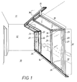
- a balcony in which the floor 10 protrudes outside of the ceiling 11, wherein the balcony delimited by the floor 10, the ceiling 11 and two side walls 12 is open to the outside and is secured there by a parapet 13.
- a guide rail 14 fastened to the floor 10 between the two side walls 12, while a rail 15 is also fastened to the ceiling 11 at a short distance from its outer end face, which springs back relative to the rail 14 but parallel to the bottom guide rail 14 runs.
- the ceiling-side rail 15 is designed as a box which is open at the bottom and has two channels 16 running next to one another, each channel 16 being divided by a web 17 which projects downwards and has a triangular web head 18 at its free end which has a raceway 19 in the longitudinal direction of the profile forms.
- This track 19 is formed from two guide tracks 20 which are inclined due to the triangular shape of the web head 18, the purpose of which is described below.
- the bottom-side guide rail 14 and the top-side rail 15 serve to hold at least two sliding wings 21 and 22 which can be displaced one behind the other, each sliding wing having two wing planes which are mutually projecting and which are connected to one another by an inclined wing section.
- Each sliding sash 21, 22 has two side frame parts 23 which are assembled from a profile bar to form a Z shape and which are connected to one another by interposed profile bars.
- a narrow profile bar 24 is inserted between the side frame parts 23 and is screwed into a screw groove 51 of the profile bar 24 by means of it Screws 25 is firmly connected to the side frame part 23.
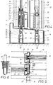
- This profile rod 24 has on the underside a receiving space for guide rollers 26, which in turn are mounted in a roller cage 27 and inserted into the cavity of the profile rod 24, as can be seen from FIG. 4.
- the profile rod 24 has a groove 28, into which a filling plate 30 is inserted with the interposition of a seal 29, which likewise engages in the same way in grooves in the side frame parts 23.
- the side frame parts 23 projecting in the vertical direction from the bottom-side guide rail 14 form, together with the profile bar 24 and a frame profile bar 31 and the filling plate 30, a wing section 32 which forms a vertical part plane of each sliding wing 21 or 22.
- a tube 33 is fastened between the side frame parts 23, to which the frame profile rod 31 is screwed with the interposition of a seal 34 (FIG. 3).
- a further, inclined wing section 35 adjoins the lower wing section 32, which is likewise delimited by a tube 33 ′ connecting the side frame parts 23 to one another.
- 23 frame profile rods 31 are also screwed to the tubes 33 and 33 'in accordance with the receiving groove in the side frame parts, also with the interposition of a seal 34.
- a circumferential groove is also formed in the middle wing section 35, into which a filling plate 30 'is inserted using a seal 29.
- the wing section 35 is then followed by a vertical wing section 36, which in turn is connected on the underside to the tube 33 'with a frame profile bar 31, while the upper wing section 36 is delimited on its upper side by an end profile bar 37, the Width corresponds to the width of the side frame part 23.
- the end profile rod 37 also has a screw groove 38, with the aid of which the end profile rod 37 can be screwed between the side frame parts 23.
- the end profile rod 37 also has a groove 28 which is open at the bottom and which together with the grooves in the side frame parts and the profile bars 31 serves to accommodate a filling plate 30 ′′ with the aid of a seal 29.
- the filling plates 3o to 3o '' are usually glass plates, although it is also conceivable to use filling plates made of another material, such as plastic.
- each roller bearing 43 is formed from roller bearings 43, the outer ring of which has a coating 44, preferably made of plastic.
- the inner ring of each roller bearing 43 forming the support roller 42 is mounted on an axle pin 45 designed as a collar bolt, which is riveted in the leg 4o or 41 of each roller holder 39 after the respective support roller 42 has been pushed on and a spacer ring.
- the mutually inclined pairs of support rollers of a roller holder 39 two of which are fastened one behind the other on the end profile rod 37, enable the sliding wings 21 and 22 to self-center on the web head 18 of the ceiling-side rail 15 even when the sliding wings are loaded by wind or snow, so that the Do not tilt the sash.
- the web heads 18 of the webs 17 of the ceiling-side guide rail 15 are provided with longitudinal centering grooves 46, into which not shown in the region of the joints of the ceiling-side rail 15 Heavy Duty Pins are used.
- Roller cages 27 with guide rollers 26 mounted therein are inserted in the profile bar 24 of the lower wing section 32.
- These guide rollers 26 have a flange 47 which engages in a guide groove 48 in the bottom guide rail 14.
- Both side cheeks 49 of the flange 47 are from the roller shell 50 to
- the outer circumference of the wheel flange 47 tapers in order to ensure that the wheel flange 47 is securely inserted into the guide groove 48 of the bottom-side guide rail 14.
- a longitudinally extending screw groove 51 is provided on the lower profile bar 24, into which a screw 25 penetrating the frame side part 23 can be screwed for the frame connection.
- this screw 25 also serves to hold a safety device which counteracts the lifting of the sliding sash from the guide groove 48.
- the shaft of the screw 25 is overlapped by the elongated hole 53 of a locking plate 52, this locking plate having at its lower end a hammer head shoulder 54 which engages in the undercut guide groove 48 of the bottom-side guide rail 14.
- a safety slide 72 can also be used, which can be made of plastic and which has an elongated shaft part 73 with a foot part 74 on the underside.
- This foot part 74 is provided with at least two securing fingers 75 which project downwards into the guide groove 48 of the bottom guide rail 14 and which on their underside have cam bars 76 which project outwards and are placed in the guide grooves 48.
- the mutually facing inside of the profile bars 24 of the respective sliding sashes 21 and 22 are connected to a U-shaped receiving profile 55 which is open at the bottom and which receives a sealing strip 56 which due to gravity has its brush-like underside rests on the surface of the bottom-side guide rail 14 and thus dampens drafts.
- the bottom-side guide rail 14 is formed from an upper U-profile bar 57, which is open on its underside and whose top runs inclined towards the outside of the building and in this inclined surface the guide grooves 48 having.
- These guide grooves have attachment strips 58 on the underside, the purpose of which is described below.
- the upper U-profile rod 57 engages over a lower U-profile rod 59, which can be advantageously fixed with its web on the floor, with pairs of strips 60 protruding from the web on the inside of this lower U-profile rod, which are provided with screw grooves 61 on their mutually facing sides are. Studs 62 are screwed into these screw grooves 61 of each pair of strips 60 and lie exactly below the top strips 58, since the pairs of strips 60 are at a distance corresponding to the distance between the guide grooves 48.
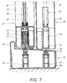
- the inner sliding sash is equipped with an actuatable locking device 63.
- a sleeve 64 is fixed in the vertical profile bar of the side frame part 23 on the inner sliding sash 21, for example by screwing in, this sleeve 64 having a spring receiving space 65 which is offset from the sleeve 64 and has a contact surface for one-sided support of a closing spring 66.
- the sleeve 64 and the locking spring 66 are penetrated by a locking pin 67, which can protrude from the sleeve 64 with a pin part 68, wherein between the pin part 68 and the shaft of the locking pin 67 a stationary approach 69 for supporting the locking spring 66 on the other End worries.
- a handle 70 is firmly connected to the locking pin 67, which rests on the end of the sleeve 64 and thus limits the stroke of the pin part 68 of the locking pin 67.
- the pin part 68 of the locking pin 67 projects into a closing recess 71 in the side frame part 23 of the outer sliding leaf 22.
- the handle 70 To move the sliding sashes 21 and 22 against one another, the handle 70 must first be transferred to the dash-dotted position shown in FIG. 5, as a result of which the pin part 68 also moves out of the Closing recess 71 of the sliding sash 22 arrives so that the sliding sash can be moved against each other.
Landscapes
- Engineering & Computer Science (AREA)
- Civil Engineering (AREA)
- Structural Engineering (AREA)
- Architecture (AREA)
- Mechanical Engineering (AREA)
- Physics & Mathematics (AREA)
- Electromagnetism (AREA)
- Specific Sealing Or Ventilating Devices For Doors And Windows (AREA)
- Support Devices For Sliding Doors (AREA)
Applications Claiming Priority (2)
| Application Number | Priority Date | Filing Date | Title |
|---|---|---|---|
| DE4435641 | 1994-10-06 | ||
| DE4435641A DE4435641C2 (de) | 1994-10-06 | 1994-10-06 | Schiebeflügel zum bedarfsweisen Verschließen, insbesondere einer offenen Seite von Balkonen, Wintergärten u. dgl. |
Publications (2)
| Publication Number | Publication Date |
|---|---|
| EP0705954A1 true EP0705954A1 (fr) | 1996-04-10 |
| EP0705954B1 EP0705954B1 (fr) | 1999-11-10 |
Family
ID=6530052
Family Applications (1)
| Application Number | Title | Priority Date | Filing Date |
|---|---|---|---|
| EP95115646A Expired - Lifetime EP0705954B1 (fr) | 1994-10-06 | 1995-10-05 | Aile coulissante pour la fermeture suivant les besoins d'une façade ouverte d'un balcon, jardin d'hiver et similaires |
Country Status (4)
| Country | Link |
|---|---|
| US (1) | US5598665A (fr) |
| EP (1) | EP0705954B1 (fr) |
| DE (1) | DE4435641C2 (fr) |
| NO (1) | NO306025B1 (fr) |
Cited By (2)
| Publication number | Priority date | Publication date | Assignee | Title |
|---|---|---|---|---|
| EP3882426A1 (fr) * | 2020-03-16 | 2021-09-22 | Ingo Kneer | Agencement de rail, dispositif de toiture et procédé de fabrication d'un agencement de rail |
| IT202300010392A1 (it) * | 2023-05-23 | 2024-11-23 | Ab Class S R L | Sistema di scorrimento inferiore per anta scorrevole |
Families Citing this family (20)
| Publication number | Priority date | Publication date | Assignee | Title |
|---|---|---|---|---|
| US5927017A (en) * | 1998-01-30 | 1999-07-27 | The Stanley Works | Sliding door bottom roller assembly with a rotatable anti-jump member |
| US6141907A (en) * | 1998-05-12 | 2000-11-07 | Parazader; Stephen | Biparting panel assembly |
| US6276091B1 (en) * | 1998-09-17 | 2001-08-21 | Jaime Carl Ridgway | Sliding glass door assembly having glass doors which are lockable together to slide as a unit |
| DE19927989A1 (de) * | 1999-06-18 | 2000-12-21 | Alfred Bohn Gmbh & Co Kg | Halte- und Führungselement für eine Verglasungsanordnung |
| KR100324496B1 (ko) * | 1999-09-10 | 2002-02-27 | 박명신 | 레일채움형 창호장치 |
| US6422287B1 (en) * | 2000-07-10 | 2002-07-23 | James Bradley Wilke | Slide/swing patio door |
| US6532699B1 (en) * | 2001-12-12 | 2003-03-18 | Regina Frances Franklin | Sliding glass door greenhouse |
| DE10329518B4 (de) * | 2003-06-30 | 2008-01-24 | Dorma Gmbh + Co. Kg | Führungseinrichtung für eine Schiebetür |
| WO2011088113A1 (fr) | 2010-01-12 | 2011-07-21 | Cabreeco Companies Llc | Enceinte mobile |
| US20110308173A1 (en) | 2009-09-04 | 2011-12-22 | Forsland Kent H | Movable building structure |
| USD616567S1 (en) * | 2009-09-28 | 2010-05-25 | Dallaire Industries Ltd. | Pull rail for patio door sash |
| USD616568S1 (en) * | 2009-09-28 | 2010-05-25 | Dallaire Industries Ltd. | Horizontal rail for patio door sash |
| USD616566S1 (en) * | 2009-09-28 | 2010-05-25 | Dallaire Industries Ltd. | Meeting rail for patio door sash |
| US8381452B1 (en) | 2010-03-08 | 2013-02-26 | Cabreeco Companies Llc | Structure having a convertible roof and sidewall |
| WO2012135903A1 (fr) * | 2011-04-05 | 2012-10-11 | Mammoth Industries Pty Ltd | Support pour une fermeture à roulement |
| AU337074S (en) * | 2011-05-16 | 2011-06-09 | Jeld Wen Australia Pty Ltd | Rail extrusion for a sliding door |
| AU337065S (en) * | 2011-05-16 | 2011-06-09 | Jeld Wen Australia Pty Ltd | Stile extrusion for a sliding door |
| US10167663B2 (en) * | 2015-12-18 | 2019-01-01 | Aldana Florencia Ferrer Garcia | Windows accessing more sky |
| US11781370B2 (en) * | 2021-06-07 | 2023-10-10 | Goldbrecht Llc | Adjustable flush threshold for sliding doors and windows |
| US12286835B1 (en) * | 2024-10-04 | 2025-04-29 | John G. Labuda | Window ventilation and insert arrangement |
Citations (8)
| Publication number | Priority date | Publication date | Assignee | Title |
|---|---|---|---|---|
| FR1191544A (fr) * | 1958-02-14 | 1959-10-20 | Baumann Fils & Cie | Perfectionnements aux dispositifs de suspensions d'éléments coulissants, notamment de portes de garage |
| US3261129A (en) * | 1964-04-06 | 1966-07-19 | Acme Appliance Mfg Company | Panel hardware |
| GB1067938A (en) * | 1964-11-17 | 1967-05-10 | Isobel Rosemary Barnes | Improvements in slidable window assemblies |
| NL7700208A (nl) * | 1976-01-14 | 1977-07-18 | Atmb Sa | Glijrail voor beweegbare elementen, die deel uit- maken van de inrichting van gebouwen. |
| DE3508536A1 (de) * | 1985-03-09 | 1986-09-11 | Jürgen 2800 Bremen Guddas | Bauelementensatz zur bildung von schiebefluegeln fuer tueren, fenster, moebel u.dgl. |
| US4633614A (en) * | 1985-04-05 | 1987-01-06 | Usg Corporation | Adjustable tub enclosure and shower stall doors |
| DE8710182U1 (de) * | 1987-07-24 | 1987-10-01 | Multimedia GmbH Gesellschaft zur Verwertung von Ideen u. Rechten, 8000 München | Abdeckvorrichtung als Witterungsschutz |
| EP0457286A1 (fr) * | 1990-05-17 | 1991-11-21 | Hespe & Woelm GmbH & Co. KG | Porte coulissante |
Family Cites Families (8)
| Publication number | Priority date | Publication date | Assignee | Title |
|---|---|---|---|---|
| CH153740A (fr) * | 1930-11-07 | 1932-04-15 | Baumann & Fils | Dispositif de fermeture par panneaux coulissants reliés entre eux par des articulations. |
| US3199155A (en) * | 1963-11-12 | 1965-08-10 | Brunswick Corp | Floor seal |
| US4453346A (en) * | 1982-05-24 | 1984-06-12 | United States Gypsum Company | Adjustable wall jamb for shower door |
| US4987638A (en) * | 1988-05-05 | 1991-01-29 | Nickolas Ribaudo | Sliding door assembly |
| US4833829A (en) * | 1988-09-14 | 1989-05-30 | Viplex Corporation | Geometric sliding door |
| US5224297A (en) * | 1991-06-10 | 1993-07-06 | Nelson A. Taylor Co., Inc. | Sliding door and latching/locking assembly |
| US5148630A (en) * | 1991-10-24 | 1992-09-22 | Mario Llorens | Security assembly for a sliding glass door |
| US5209018A (en) * | 1992-03-12 | 1993-05-11 | Heinrich William I | Sliding patio door improvement |
-
1994
- 1994-10-06 DE DE4435641A patent/DE4435641C2/de not_active Expired - Fee Related
-
1995
- 1995-10-05 EP EP95115646A patent/EP0705954B1/fr not_active Expired - Lifetime
- 1995-10-05 NO NO953963A patent/NO306025B1/no not_active IP Right Cessation
- 1995-10-06 US US08/540,049 patent/US5598665A/en not_active Expired - Fee Related
Patent Citations (8)
| Publication number | Priority date | Publication date | Assignee | Title |
|---|---|---|---|---|
| FR1191544A (fr) * | 1958-02-14 | 1959-10-20 | Baumann Fils & Cie | Perfectionnements aux dispositifs de suspensions d'éléments coulissants, notamment de portes de garage |
| US3261129A (en) * | 1964-04-06 | 1966-07-19 | Acme Appliance Mfg Company | Panel hardware |
| GB1067938A (en) * | 1964-11-17 | 1967-05-10 | Isobel Rosemary Barnes | Improvements in slidable window assemblies |
| NL7700208A (nl) * | 1976-01-14 | 1977-07-18 | Atmb Sa | Glijrail voor beweegbare elementen, die deel uit- maken van de inrichting van gebouwen. |
| DE3508536A1 (de) * | 1985-03-09 | 1986-09-11 | Jürgen 2800 Bremen Guddas | Bauelementensatz zur bildung von schiebefluegeln fuer tueren, fenster, moebel u.dgl. |
| US4633614A (en) * | 1985-04-05 | 1987-01-06 | Usg Corporation | Adjustable tub enclosure and shower stall doors |
| DE8710182U1 (de) * | 1987-07-24 | 1987-10-01 | Multimedia GmbH Gesellschaft zur Verwertung von Ideen u. Rechten, 8000 München | Abdeckvorrichtung als Witterungsschutz |
| EP0457286A1 (fr) * | 1990-05-17 | 1991-11-21 | Hespe & Woelm GmbH & Co. KG | Porte coulissante |
Cited By (2)
| Publication number | Priority date | Publication date | Assignee | Title |
|---|---|---|---|---|
| EP3882426A1 (fr) * | 2020-03-16 | 2021-09-22 | Ingo Kneer | Agencement de rail, dispositif de toiture et procédé de fabrication d'un agencement de rail |
| IT202300010392A1 (it) * | 2023-05-23 | 2024-11-23 | Ab Class S R L | Sistema di scorrimento inferiore per anta scorrevole |
Also Published As
| Publication number | Publication date |
|---|---|
| NO306025B1 (no) | 1999-09-06 |
| NO953963L (no) | 1996-04-09 |
| EP0705954B1 (fr) | 1999-11-10 |
| NO953963D0 (no) | 1995-10-05 |
| DE4435641A1 (de) | 1996-04-11 |
| US5598665A (en) | 1997-02-04 |
| DE4435641C2 (de) | 1998-12-03 |
Similar Documents
| Publication | Publication Date | Title |
|---|---|---|
| DE4435641C2 (de) | Schiebeflügel zum bedarfsweisen Verschließen, insbesondere einer offenen Seite von Balkonen, Wintergärten u. dgl. | |
| EP2685039B1 (fr) | Dispositif de guidage, chariot et rail de guidage | |
| DE1584189B1 (de) | Kombinierter Schwenk- und Schiebetuermechanismus | |
| DE202018001610U1 (de) | Antriebsvorrichtung mit einem Zahnstangenelement für einen verschiebbaren Flügel als Schiebeflügel oder verschiebbaren Hebe-Schiebeflügel eines Fensters oder einer Tür | |
| DE68907768T2 (de) | Faltwand, bestehend aus miteinander gelenkig verbundenen doppelwandigen Flügeln. | |
| WO2016113224A1 (fr) | Système de battants coulissants et rotatifs | |
| DE19725355C2 (de) | Schiebetürschließeinrichtung | |
| DE69516131T2 (de) | Struktur zum Anordnen von Schiebetüren | |
| EP1485563B1 (fr) | Dispositif de support et de guidage permettant de fixer des elements porte ou mur mobiles suspendus | |
| EP1496182A2 (fr) | Système de portes coulissantes avec une pluralité de panneaux coulissants | |
| EP0679788B1 (fr) | Chariot ainsi qu'ensemble coulissant et rail | |
| DE3814535C2 (fr) | ||
| DE202018001609U1 (de) | Antriebsvorrichtung für einen verschiebbaren Flügel als Schiebeflügel oder verschiebbaren Hebe-Schiebeflügel eines Fensters oder einer Tür | |
| DE102015107324B4 (de) | Profilschienensystem für den Einbau von Schiebetüren in Hohlwände | |
| WO2025056287A1 (fr) | Ferrure de porte coulissante et agencement de porte coulissante associé | |
| EP3816383B1 (fr) | Agencement de porte coulissante | |
| DE9100963U1 (de) | Laufwerksanordnung für ein Schiebetor | |
| DE202005003872U1 (de) | Führungssystem zum Führen von Schiebetüren oder Schiebefenstern | |
| EP1403459A2 (fr) | Paroi de séparation avec éléments coulissant horizontalement | |
| DE19539014A1 (de) | Schiebetürbeschlag | |
| DE19715712C2 (de) | Sektionaltor | |
| DE19835684A1 (de) | Verfahrbare Türflügelanordnung | |
| DE2416960C2 (de) | Schwenkzapfenausbildung | |
| DE3517291C2 (fr) | ||
| DE2708453C3 (de) | Kastenaufbau für Fahrzeuge mit mindestens einer verschiebbaren Tür |
Legal Events
| Date | Code | Title | Description |
|---|---|---|---|
| PUAI | Public reference made under article 153(3) epc to a published international application that has entered the european phase |
Free format text: ORIGINAL CODE: 0009012 |
|
| AK | Designated contracting states |
Kind code of ref document: A1 Designated state(s): BE ES FR GB NL |
|
| RBV | Designated contracting states (corrected) |
Designated state(s): BE ES FR GB NL |
|
| 17P | Request for examination filed |
Effective date: 19960809 |
|
| REG | Reference to a national code |
Ref country code: DE Ref legal event code: 8566 |
|
| GRAG | Despatch of communication of intention to grant |
Free format text: ORIGINAL CODE: EPIDOS AGRA |
|
| 17Q | First examination report despatched |
Effective date: 19990319 |
|
| GRAG | Despatch of communication of intention to grant |
Free format text: ORIGINAL CODE: EPIDOS AGRA |
|
| GRAH | Despatch of communication of intention to grant a patent |
Free format text: ORIGINAL CODE: EPIDOS IGRA |
|
| GRAH | Despatch of communication of intention to grant a patent |
Free format text: ORIGINAL CODE: EPIDOS IGRA |
|
| GRAA | (expected) grant |
Free format text: ORIGINAL CODE: 0009210 |
|
| PUAC | Information related to the publication of a b1 document modified or deleted |
Free format text: ORIGINAL CODE: 0009299EPPU |
|
| STAA | Information on the status of an ep patent application or granted ep patent |
Free format text: STATUS: THE APPLICATION HAS BEEN WITHDRAWN |
|
| AK | Designated contracting states |
Kind code of ref document: B1 Designated state(s): BE ES FR GB NL |
|
| 18W | Application withdrawn |
Withdrawal date: 19991016 |
|
| DB1 | Publication of patent cancelled |