EP0705973B1 - Anlasser mit bandförmigem Abdichtungselement - Google Patents
Anlasser mit bandförmigem Abdichtungselement Download PDFInfo
- Publication number
- EP0705973B1 EP0705973B1 EP95101173A EP95101173A EP0705973B1 EP 0705973 B1 EP0705973 B1 EP 0705973B1 EP 95101173 A EP95101173 A EP 95101173A EP 95101173 A EP95101173 A EP 95101173A EP 0705973 B1 EP0705973 B1 EP 0705973B1
- Authority
- EP
- European Patent Office
- Prior art keywords
- seal member
- band
- yoke
- shaped seal
- starter
- Prior art date
- Legal status (The legal status is an assumption and is not a legal conclusion. Google has not performed a legal analysis and makes no representation as to the accuracy of the status listed.)
- Expired - Lifetime
Links
Images


Classifications
-
- H—ELECTRICITY
- H02—GENERATION; CONVERSION OR DISTRIBUTION OF ELECTRIC POWER
- H02K—DYNAMO-ELECTRIC MACHINES
- H02K5/00—Casings; Enclosures; Supports
- H02K5/04—Casings or enclosures characterised by the shape, form or construction thereof
-
- F—MECHANICAL ENGINEERING; LIGHTING; HEATING; WEAPONS; BLASTING
- F02—COMBUSTION ENGINES; HOT-GAS OR COMBUSTION-PRODUCT ENGINE PLANTS
- F02N—STARTING OF COMBUSTION ENGINES; STARTING AIDS FOR SUCH ENGINES, NOT OTHERWISE PROVIDED FOR
- F02N11/00—Starting of engines by means of electric motors
-
- H—ELECTRICITY
- H02—GENERATION; CONVERSION OR DISTRIBUTION OF ELECTRIC POWER
- H02K—DYNAMO-ELECTRIC MACHINES
- H02K5/00—Casings; Enclosures; Supports
- H02K5/04—Casings or enclosures characterised by the shape, form or construction thereof
- H02K5/10—Casings or enclosures characterised by the shape, form or construction thereof with arrangements for protection from ingress, e.g. water or fingers
-
- H—ELECTRICITY
- H02—GENERATION; CONVERSION OR DISTRIBUTION OF ELECTRIC POWER
- H02K—DYNAMO-ELECTRIC MACHINES
- H02K5/00—Casings; Enclosures; Supports
- H02K5/04—Casings or enclosures characterised by the shape, form or construction thereof
- H02K5/22—Auxiliary parts of casings not covered by groups H02K5/06-H02K5/20, e.g. shaped to form connection boxes or terminal boxes
-
- H—ELECTRICITY
- H02—GENERATION; CONVERSION OR DISTRIBUTION OF ELECTRIC POWER
- H02K—DYNAMO-ELECTRIC MACHINES
- H02K2205/00—Specific aspects not provided for in the other groups of this subclass relating to casings, enclosures, supports
- H02K2205/09—Machines characterised by drain passages or by venting, breathing or pressure compensating means
Definitions
- the present invention generally relates to a starter having a band-shaped seal member and, more particularly, it relates to a starter for automobiles.
- a heat contraction tube was used to cover one engagement or coupling portion between a yoke and a housing and the other engagement or coupling portion between the yoke and an end frame as a waterproof seal.
- Document DE-A-3422235 discloses an electric motor in accordance with the preamble of claim 1.
- This known electric motor has a band-shaped seal member wrapped around an outer circumference of a stator core as well as around boundary portions of outer circumferences of end frames arranged adjacent to the end faces thereof.
- the band-shaped seal member when sealing the electric motor in the manner as above described it is likely that ventilation hole portions provided at the stator core or at the boundary portions between the stator core and the end frames are also covered by the band-shaped seal member so that a required ventilation effect is lost.
- the object of the present invention is to be seen in providing a starter having a band-shaped seal member which assures ventilation of the starter.
- the starter in accordance with the present invention comprises a band-shaped seal member which is provided and wrapped around an outer circumference of at least one of a first engagement portion between a starter yoke and a housing and a second engagement portion between said starter yoke and an end frame such that a ventilation hole portion of at least one of said starter yoke, said housing and said end frame is maintained open to the outside, thereby keeping the ventilation effect of the ventilation hole.
- the seal member is stuck or adhered to the yoke, and surface treatment of the yoke is not required, thereby reducing costs.
- the sealing member such as an O-ring used conventionally on the yoke engagement portion can be eliminated, thereby eliminating machining costs and lowering total production cost.
- a clearance at the end portion is made to correspond to a ventilation hole portion of the yoke, housing or end frame, so the ventilation function is attained thereby.
- the band-shaped seal member has a hole portion which corresponds to the ventilation hole portion of the yoke, housing or end frame, so the ventilation function is attained thereby.
- the band-shaped seal member is wound multiple times to overlay, so commercially available seal members can be used.
- an outer surface of the band-shaped seal member can be used for a nameplate or caution plate, so the number of parts can be reduced.
- the band-shaped seal member can be easily mounted thereby improving the mounting efficiency.
- a band-shaped seal member 1 is wound on a starter, which is well known and the description is omitted for brevity, and is made of a material such as polyester, vinyl, paper, cloth, synthetic resin film, metal foil such as aluminum foil, stretchy rubber material or stretchy cloth material. Adhesive is applied on the inner circumference of the seal member 1, and a nameplate la indicating the manufacturer, part numbers, date of manufacture or cautionary item is printed on the outer surface of the seal member 1.
- the seal member 1 covers a cylindrical field yoke 2 with permanent magnets 8, a disk-like center plate 3, a housing 4 encasing pinion (not illustrated) therein, a disk-like brush holder 5, and an end frame 6 encasing a magnet switch (not illustrated) horiaontally or vertically therein and supporting a battery terminal 9 and a switch terminal 11.
- the seal member 1 covers two circular engagement or coupling portions, one between the yoke 2 and the housing 4 and the other between the yoke 2 and the end frame 6.
- This seal member 1 has a clearance 1b between the circumferential ends of the member 1 so that a notched ventilation hole 5a on the brush holder 5 and yoke 2 can be opened in the direction of the starter bottom as illustrated in Fig. 2 and Figs. 3A and 3B.
- the material of the band-shaped seal member 1 in this embodiment is most preferably polyester film.
- the surfaces of the field yoke 2, the center plate 3, the housing 4 and the brush holder 5 can be treated with plating or paint, but as they are covered by the band-shaped seal member 1, this surface treatment can be eliminated.
- the surface does not need to be treated. Even if the end frame 6 is made of metal, the surface does not need to be treated if the frame 6 is covered with the band-shaped seal member 1.
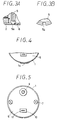
- a through bolt 7 is placed on a concave portion 2a formed on the yoke 2 and extending radially inwardly between the field yoke 2 and magnets 8, so the amount that it protrudes from the outer circumference of the field yoke 2 is reduced, thereby making the winding of the band-shaped seal member 1 is adhered to the yoke 2 easier.
- the band-shaped seal member 1 is stuck along a base 7a of the through bolt 7 and a curved convex portion of a screw base 4a of the housing 4.
- the band-shaped seal member 1 can have a multiple portion 1c that covers the joints or coupling portions of the starter where no ventilation holes are formed. Furthermore, as shown in Fig. 5, if the through bolt 7 is placed on the inner diameter side of the field yoke outer diameter, the sticking work and the sticking properties of the band-shaped seal member can be further improved.
- the band-shaped seal member 1 can also be wound multiple times to overlay as shown in Fig. 6.
- a hole portion 1d can be formed on the band-shaped seal member 1 so that this hole 1d is made to correspond to the notched ventilation hole 5a formed on the yoke 2 shown in Fig. 7, or to the ventilation hole formed on the housing 4 or end frame 6.
- the heat to the starter from an engine or exhaust system can be insulated.
- heat insulating material e.g., aluminum foil, asbestos
- the contact properties will further increase, and will be especially suitable for the multiple windings shown in Fig. 6.
- the seal member 1 in the above embodiment covers the outer circumference of the starter by approximately 360 degrees.
- the coupling portion can be covered in the range A that is at least 180 degrees so that the upper half of the starter is covered when mounted on the engine.
- the seal can be made just between the outer circumference of the coupling between the yoke 2 and the housing 4 with the band-shaped seal member 1.
- the battery terminal 9 of the end frame 6 is also used as a seal by mold fixing.
- the space between the switch terminal 11 and the motor cover 6 is sealed by seal 10.
Landscapes
- Engineering & Computer Science (AREA)
- Power Engineering (AREA)
- Chemical & Material Sciences (AREA)
- Combustion & Propulsion (AREA)
- Mechanical Engineering (AREA)
- General Engineering & Computer Science (AREA)
- Connection Of Motors, Electrical Generators, Mechanical Devices, And The Like (AREA)
- Motor Or Generator Frames (AREA)
Claims (12)
- Anlasser mit:einem Polgehäuse (2), das Magnetpole (8) aufweist, die am Innenumfang des Polgehäuses (2) angeordnet sind,einem Gehäuse (4), das mit dem einen Ende des Polgehäuses (2) in Eingriff steht, und/oder einem Endrahmen (6), der mit dem anderen Ende des Polgehäuses (2) in Eingriff steht, undeinem bandförmigen Abdichtelement (1), das so angebracht ist, daß es den Außenumfang eines ersten Eingriffsabschnitts zwischen dem Polgehäuse (2) und dem Gehäuse (4) und/oder eines zweiten Eingriffsabschnitts zwischen dem Polgehäuse (2) und dem Endrahmen (6) abdichtet, dadurch gekennzeichnet, daßdas Polgehäuse (2), das Gehäuse (4) und/oder der Endrahmen (6) eine die Innenseite mit der Außenseite verbindende Entlüftungsaussparung (5a) aufweist/aufweisen unddas bandförmige Abdichtelement (1) so vorgesehen und herumgewickelt ist, daß über die Belüftungsaussparung (5a) eine ständige Verbindung zwischen der Innenseite und der Außenseite möglich ist.
- Anlasser nach Anspruch 1, wobei das bandförmige Abdichtelement (1) ein Klebematerial aufweist.
- Anlasser nach Anspruch 1 oder 2, wobei in Umfangsrichtung zwischen den Enden des bandförmigen Abdichtelements ein Abstand (1b) ausgebildet, der der Belüftungsaussparung (5a) des Polgehäuses (2), des Gehäuses (4) und/oder des Endrahmens (6) entsprechend angeordnet ist.
- Anlasser nach Anspruch 1 oder 2, wobei das bandförmige Abdichtelement (1) eine Aussparung (ld) aufweist, die der Belüftungsaussparung (5a) des Polgehäuses (2), des Gehäuses (4) und/oder des Endrahmens (6) entsprechend angeordnet ist.
- Anlasser nach einem der Ansprüche 1 bis 4, wobei das bandförmige Abdichtelement (1) in Axialrichtung geneigt, mehrfach übereinander gelagert und um den Außenumfang (Fig. 6) herumgewickelt ist.
- Anlasser nach einem der Ansprüche 1 bis 5, wobei das Abdichtelement (1) ein schallabsorbierendes Material und/oder ein isolierendes Material aufweist.
- Anlasser nach einem der Ansprüche 1 bis 6, wobei das bandförmige Abdichtelement (1) ferner als Typenschild und/oder Warnschild (la) verwendet wird.
- Anlasser nach einem der Ansprüche 1 bis 7, wobei der Endrahmen (6) einen Magnetschalter einschließt.
- Anlasser nach einem der Ansprüche 1 bis 8, wobei das bandförmige Abdichtelement (1) so herumgewickelt ist, daß es die gesamte Außenfläche des Polgehäuses (2) bedeckt.
- Anlasser nach einem der Ansprüche 1 bis 9, wobei die Belüftungsaussparung (5a) an einem Bodenabschnitt des Gehäuses (4), des Endrahmens (6) und des Polgehäuses (2) ausgebildet ist.
- Anlasser nach einem der Ansprüche 1 bis 10, wobei das Polgehäuse (2) einen konkaven Abschnitt (2a) zur Aufnahme einer Durchgangsschraube (7) aufweist und das bandförmige Abdichtelement (1) so herumgewickelt ist, daß es über der Schraube (7) liegt.
- Anlasser nach Anspruch 11, wobei das bandförmige Abdichtelement (1) derart spiralförmig herumgewickelt ist, daß dessen seitliche Ränder überlappen.
Applications Claiming Priority (2)
| Application Number | Priority Date | Filing Date | Title |
|---|---|---|---|
| JP241140/94 | 1994-10-05 | ||
| JP24114094 | 1994-10-05 |
Publications (2)
| Publication Number | Publication Date |
|---|---|
| EP0705973A1 EP0705973A1 (de) | 1996-04-10 |
| EP0705973B1 true EP0705973B1 (de) | 1999-04-07 |
Family
ID=17069874
Family Applications (1)
| Application Number | Title | Priority Date | Filing Date |
|---|---|---|---|
| EP95101173A Expired - Lifetime EP0705973B1 (de) | 1994-10-05 | 1995-01-27 | Anlasser mit bandförmigem Abdichtungselement |
Country Status (3)
| Country | Link |
|---|---|
| US (1) | US5521441A (de) |
| EP (1) | EP0705973B1 (de) |
| DE (1) | DE69508878T2 (de) |
Families Citing this family (9)
| Publication number | Priority date | Publication date | Assignee | Title |
|---|---|---|---|---|
| US5945755A (en) * | 1994-09-20 | 1999-08-31 | Denso Corporation | Starter with housing for cantilever-mounting on engine |
| US5698914A (en) * | 1994-09-20 | 1997-12-16 | Nippondenso Co., Ltd. | Starter with a discharge hole on a yoke |
| US5626464A (en) * | 1995-05-23 | 1997-05-06 | Aquatec Water Systems, Inc. | Wobble plate pump |
| JP2002180938A (ja) * | 2000-12-08 | 2002-06-26 | Denso Corp | スタータ |
| DE10339572A1 (de) * | 2003-08-28 | 2005-04-07 | Audi Ag | Starter-Generator-Vorrichtung für Kraftfahrzeuge |
| DE102005003077B4 (de) * | 2005-01-22 | 2011-06-16 | Audi Ag | Antriebseinheit für ein Kraftfahrzeug |
| CN101203996B (zh) * | 2005-06-23 | 2012-06-13 | 株式会社美姿把 | 起动器 |
| DE102009045281B4 (de) * | 2009-10-02 | 2020-08-27 | Seg Automotive Germany Gmbh | Startvorrichtung mit einem Relais |
| DE102017212190B4 (de) * | 2017-07-17 | 2024-02-01 | Audi Ag | Elektrische Maschine und Kraftfahrzeug |
Family Cites Families (9)
| Publication number | Priority date | Publication date | Assignee | Title |
|---|---|---|---|---|
| US3419957A (en) * | 1965-01-29 | 1969-01-07 | Controls Co Of America | Method of making an electric motor |
| US3735173A (en) * | 1971-11-24 | 1973-05-22 | Simmonds Precision Products | Electric motor construction |
| JPS60186852U (ja) * | 1984-05-17 | 1985-12-11 | 三菱電機株式会社 | 電動機の防水装置 |
| DE3422235A1 (de) * | 1984-06-15 | 1985-12-19 | Standard Elektrik Lorenz Ag, 7000 Stuttgart | Elektromotor |
| US4720648A (en) * | 1986-02-28 | 1988-01-19 | Emerson Electric Co. | Protective cover for slotted motor housing shell structure |
| DE3874157T2 (de) * | 1987-01-23 | 1993-03-25 | Mitsubishi Electric Corp | Anlasser fuer verbrennungsmotor. |
| JPH0354342U (de) * | 1989-09-29 | 1991-05-27 | ||
| DE3935299A1 (de) * | 1989-10-24 | 1991-04-25 | Bosch Gmbh Robert | Umhuellung fuer elektrische maschinen |
| CA2063612A1 (en) * | 1992-03-20 | 1993-09-21 | Andre A. Ferlatte | Motor protection device |
-
1995
- 1995-01-27 EP EP95101173A patent/EP0705973B1/de not_active Expired - Lifetime
- 1995-01-27 DE DE69508878T patent/DE69508878T2/de not_active Expired - Fee Related
- 1995-01-31 US US08/381,404 patent/US5521441A/en not_active Expired - Fee Related
Also Published As
| Publication number | Publication date |
|---|---|
| DE69508878T2 (de) | 1999-12-02 |
| US5521441A (en) | 1996-05-28 |
| EP0705973A1 (de) | 1996-04-10 |
| DE69508878D1 (de) | 1999-05-12 |
Similar Documents
| Publication | Publication Date | Title |
|---|---|---|
| KR910010201B1 (ko) | 무브러시 모터 | |
| US5500994A (en) | Method of manufacturing a rotor | |
| US4769624A (en) | Permanent magnet assembly | |
| EP0705973B1 (de) | Anlasser mit bandförmigem Abdichtungselement | |
| US5874794A (en) | Method for securing magnets to a permanent magnet motor shell and a motor made therefrom | |
| JPH09261935A (ja) | ブラシレスdcモータ | |
| CN112583177A (zh) | 马达和变速器装置 | |
| US4506180A (en) | Fixed field inductor-type generator | |
| US8813586B2 (en) | Starter motor having seal plate to seal bearing box formed in end frame | |
| JP4234447B2 (ja) | ブラシホルダの製造方法、ブラシホルダ及びモータ | |
| EP1168570A2 (de) | Spulenwicklung für eine DC-Maschine | |
| US6509662B2 (en) | DC motor | |
| JP3592089B2 (ja) | 回転電気機械 | |
| EP0940906A2 (de) | Gehäuseaufbau eines elektromotors | |
| EP1202437A2 (de) | Doppelt isolierter Motoranker | |
| JPH11215745A (ja) | 電動モータ及びステータコアの形成方法 | |
| JPH08284784A (ja) | スタータ | |
| JPH07322552A (ja) | 小型モータ | |
| JP3644324B2 (ja) | スタータ用マグネットスイッチ | |
| JP2005027383A (ja) | 回転電機におけるブラケット | |
| JP2589135Y2 (ja) | 電動パワーステアリング装置 | |
| JPH0799747A (ja) | モ−ルド電動機 | |
| JP2004208400A (ja) | アウターロータ型モータ | |
| JPS63110944A (ja) | ブラシレスモ−トルの回転子構造 | |
| JP3052708B2 (ja) | 回転電機の製造方法 |
Legal Events
| Date | Code | Title | Description |
|---|---|---|---|
| PUAI | Public reference made under article 153(3) epc to a published international application that has entered the european phase |
Free format text: ORIGINAL CODE: 0009012 |
|
| 17P | Request for examination filed |
Effective date: 19950127 |
|
| AK | Designated contracting states |
Kind code of ref document: A1 Designated state(s): DE FR GB IT |
|
| RAP1 | Party data changed (applicant data changed or rights of an application transferred) |
Owner name: DENSO CORPORATION |
|
| 17Q | First examination report despatched |
Effective date: 19971114 |
|
| GRAG | Despatch of communication of intention to grant |
Free format text: ORIGINAL CODE: EPIDOS AGRA |
|
| GRAG | Despatch of communication of intention to grant |
Free format text: ORIGINAL CODE: EPIDOS AGRA |
|
| GRAH | Despatch of communication of intention to grant a patent |
Free format text: ORIGINAL CODE: EPIDOS IGRA |
|
| GRAH | Despatch of communication of intention to grant a patent |
Free format text: ORIGINAL CODE: EPIDOS IGRA |
|
| GRAA | (expected) grant |
Free format text: ORIGINAL CODE: 0009210 |
|
| AK | Designated contracting states |
Kind code of ref document: B1 Designated state(s): DE FR GB IT |
|
| ITF | It: translation for a ep patent filed | ||
| REF | Corresponds to: |
Ref document number: 69508878 Country of ref document: DE Date of ref document: 19990512 |
|
| ET | Fr: translation filed | ||
| PLBE | No opposition filed within time limit |
Free format text: ORIGINAL CODE: 0009261 |
|
| STAA | Information on the status of an ep patent application or granted ep patent |
Free format text: STATUS: NO OPPOSITION FILED WITHIN TIME LIMIT |
|
| 26N | No opposition filed | ||
| REG | Reference to a national code |
Ref country code: GB Ref legal event code: IF02 |
|
| PGFP | Annual fee paid to national office [announced via postgrant information from national office to epo] |
Ref country code: GB Payment date: 20070124 Year of fee payment: 13 |
|
| PGFP | Annual fee paid to national office [announced via postgrant information from national office to epo] |
Ref country code: DE Payment date: 20070125 Year of fee payment: 13 |
|
| PGFP | Annual fee paid to national office [announced via postgrant information from national office to epo] |
Ref country code: IT Payment date: 20070601 Year of fee payment: 13 |
|
| PGFP | Annual fee paid to national office [announced via postgrant information from national office to epo] |
Ref country code: FR Payment date: 20070109 Year of fee payment: 13 |
|
| GBPC | Gb: european patent ceased through non-payment of renewal fee |
Effective date: 20080127 |
|
| PG25 | Lapsed in a contracting state [announced via postgrant information from national office to epo] |
Ref country code: DE Free format text: LAPSE BECAUSE OF NON-PAYMENT OF DUE FEES Effective date: 20080801 |
|
| REG | Reference to a national code |
Ref country code: FR Ref legal event code: ST Effective date: 20081029 |
|
| PG25 | Lapsed in a contracting state [announced via postgrant information from national office to epo] |
Ref country code: GB Free format text: LAPSE BECAUSE OF NON-PAYMENT OF DUE FEES Effective date: 20080127 |
|
| PG25 | Lapsed in a contracting state [announced via postgrant information from national office to epo] |
Ref country code: FR Free format text: LAPSE BECAUSE OF NON-PAYMENT OF DUE FEES Effective date: 20080131 |
|
| PG25 | Lapsed in a contracting state [announced via postgrant information from national office to epo] |
Ref country code: IT Free format text: LAPSE BECAUSE OF NON-PAYMENT OF DUE FEES Effective date: 20080127 |