EP0705974A2 - Lagerung einer vertikalachsigen Wasserkraftmaschinenwelle - Google Patents
Lagerung einer vertikalachsigen Wasserkraftmaschinenwelle Download PDFInfo
- Publication number
- EP0705974A2 EP0705974A2 EP95810589A EP95810589A EP0705974A2 EP 0705974 A2 EP0705974 A2 EP 0705974A2 EP 95810589 A EP95810589 A EP 95810589A EP 95810589 A EP95810589 A EP 95810589A EP 0705974 A2 EP0705974 A2 EP 0705974A2
- Authority
- EP
- European Patent Office
- Prior art keywords
- support
- bearing
- ring
- star
- rocker
- Prior art date
- Legal status (The legal status is an assumption and is not a legal conclusion. Google has not performed a legal analysis and makes no representation as to the accuracy of the status listed.)
- Granted
Links
Images

Classifications
-
- F—MECHANICAL ENGINEERING; LIGHTING; HEATING; WEAPONS; BLASTING
- F03—MACHINES OR ENGINES FOR LIQUIDS; WIND, SPRING, OR WEIGHT MOTORS; PRODUCING MECHANICAL POWER OR A REACTIVE PROPULSIVE THRUST, NOT OTHERWISE PROVIDED FOR
- F03B—MACHINES OR ENGINES FOR LIQUIDS
- F03B11/00—Parts or details not provided for in, or of interest apart from, the preceding groups, e.g. wear-protection couplings, between turbine and generator
- F03B11/06—Bearing arrangements
- F03B11/063—Arrangements for balancing axial thrust
- F03B11/066—Arrangements for balancing axial thrust in vertical axis machines
-
- F—MECHANICAL ENGINEERING; LIGHTING; HEATING; WEAPONS; BLASTING
- F16—ENGINEERING ELEMENTS AND UNITS; GENERAL MEASURES FOR PRODUCING AND MAINTAINING EFFECTIVE FUNCTIONING OF MACHINES OR INSTALLATIONS; THERMAL INSULATION IN GENERAL
- F16C—SHAFTS; FLEXIBLE SHAFTS; ELEMENTS OR CRANKSHAFT MECHANISMS; ROTARY BODIES OTHER THAN GEARING ELEMENTS; BEARINGS
- F16C17/00—Sliding-contact bearings for exclusively rotary movement
- F16C17/04—Sliding-contact bearings for exclusively rotary movement for axial load only
- F16C17/06—Sliding-contact bearings for exclusively rotary movement for axial load only with tiltably-supported segments, e.g. Michell bearings
-
- F—MECHANICAL ENGINEERING; LIGHTING; HEATING; WEAPONS; BLASTING
- F16—ENGINEERING ELEMENTS AND UNITS; GENERAL MEASURES FOR PRODUCING AND MAINTAINING EFFECTIVE FUNCTIONING OF MACHINES OR INSTALLATIONS; THERMAL INSULATION IN GENERAL
- F16C—SHAFTS; FLEXIBLE SHAFTS; ELEMENTS OR CRANKSHAFT MECHANISMS; ROTARY BODIES OTHER THAN GEARING ELEMENTS; BEARINGS
- F16C41/00—Other accessories, e.g. devices integrated in the bearing not relating to the bearing function as such
- F16C41/02—Arrangements for equalising the load on a plurality of bearings or their elements
-
- Y—GENERAL TAGGING OF NEW TECHNOLOGICAL DEVELOPMENTS; GENERAL TAGGING OF CROSS-SECTIONAL TECHNOLOGIES SPANNING OVER SEVERAL SECTIONS OF THE IPC; TECHNICAL SUBJECTS COVERED BY FORMER USPC CROSS-REFERENCE ART COLLECTIONS [XRACs] AND DIGESTS
- Y02—TECHNOLOGIES OR APPLICATIONS FOR MITIGATION OR ADAPTATION AGAINST CLIMATE CHANGE
- Y02E—REDUCTION OF GREENHOUSE GAS [GHG] EMISSIONS, RELATED TO ENERGY GENERATION, TRANSMISSION OR DISTRIBUTION
- Y02E10/00—Energy generation through renewable energy sources
- Y02E10/20—Hydro energy
Definitions
- the invention relates to a vertical-axis hydropower machine, with a shaft mounted in a bearing support star, which shaft has a race for a support bearing, and support bearing segments are provided which are supported by adjusting elements on a support ring fixedly connected to the bearing support star.
- a vertical-axis hydropower machine of this type is known, for example, from EP-0 586 861 A1.
- the invention has for its object to provide a vertical-axis hydropower machine, the support bearing segments are individually adjustable, and which allows a small overall height with optimal accessibility of the adjusting elements.
- adjusting elements are designed as radially extending rocker arms which act on the one hand on said support ring and on the other hand on the support bearing segment, and in that the free lever arm acts on the bearing support star via adjusting means.
- the rocker arms can act either as one- or two-armed levers, with the shorter lever arm coming radially inwards and between the said support ring and the support bearing segment.
- the rocker arms take up little space in the axial direction. Your space requirement in this dimension is comparable to known elastic segment support arrangements with spring plates or feather beds. Depending on the geometry of the rocker arms, for example the cross section and / or length of the longer lever arm, these are elastic transversely to their longitudinal direction. This also makes the support of the support bearing segments resilient. It is possible to calculate the bending of the rocker arms (bending beam) under load very precisely. It can easily be measured during assembly. Monitoring the deflection of the "beam” is also easily possible during operation, for example with known capacitive distance sensors.
- a shaft 1 of a vertical-axis hydropower machine is formed in one piece with a support head 2, or the support head 2 'is made in two pieces with the shaft 1, the shaft 1 being supported by a support ring 1a.
- the support head 2 has a on the outer circumference Running surface 3 of the guide bearing and on the end face a running surface 4 of the support bearing.
- the guide bearing segment 5 of the guide bearing is supported on the inner circumference of the bearing support star, of which only the lower ring 6, the pull ring, and the upper ring 7, the pressure ring, and a radial rib 8 connecting the two rings 6 and 7, are visible in FIG are.
- the ribs 8 are provided with a recess at the radially inner end.
- a support ring 9 is welded all around with the projecting end 8a of all the ribs 8 and the lower ring 6 of the bearing support star.
- a stiffening ring 10 is placed on the radially extending edges of the projecting ends 8a of the ribs 8 and welded to them.
- the support bearing segments 12 each rest on a segment plate 13.
- Rocker arms 14 are provided for height adjustment of the support bearing segments 12. These are designed as two-armed levers, as the enlarged representation according to FIG. 3 shows compared to FIG. They have no pivot point in the real sense. Its "fulcrum” forms a cylindrical section-shaped material extension 15 on the underside of the rocker arm 13, which rests on the upper end face of the support ring 9. On the upper side, a dome-shaped material extension 16 is provided at the radially inner end of the rocker arm 14, which lies against the underside of the segment plate 13.
- rocker arm 14 At the radially outer end of the rocker arm 14 there is a horizontal bore in which a bolt 17 is located with a threaded bore extending transversely to the longitudinal axis of the bolt. A threaded rod 18 is screwed into this, which is guided through a threaded bushing 19 in the upper ring 7 of the bearing support star. The upper end of the threaded rod 18 has a square 20. A lock nut 21 is used for securing. After loosening the lock nut 21, the rocker arm 14 can be moved up or down by turning the threaded rod 18 to the left or right, and thus the associated segment plate 13 and the associated support bearing segment 12 more or less to the Tread 4 of the support bearing are pressed.
- each segment load can be precisely determined and set.
- the ratio of the lever arms h i / h a can be freely selected within wide limits, the length of the outer, longer lever arm h a and its cross-section also determining the elasticity of the supporting segment support.
- the distance d between the underside of the rocker arm 14 and the radially running edge of the projecting end 8a of the rib 8 serves as an easy-to-measure standard dimension during the assembly of the machine. It can also be easily monitored during operation, e.g. in a manner known per se by means of capacitive distance measurement.
- cams 22 or ring segments 22 ' are provided in pairs for lateral guidance of the rocker arms 14 on the upper end face of the support ring 9. These cams 22 or ring segments 22a prevent displacement of the rocker arms 14 in the circumferential direction due to torque.
- the rocker arms 14 are secured in the radial direction in the rocker arms 14 by means of horizontally extending bolts 23 arranged in pairs.
- the seal against the bearing support star is provided by a partition wall (not shown in FIG. 1), which is connected to the two Rings 6 and 7 and is welded to the ribs 8 and normally has a mounting opening which can be closed by a mounting cover and which has likewise been omitted in FIG. 1.
- a rocker arm 14 acting as a two-armed lever
- a rocker arm 14 'acting as a one-armed lever can also be used according to FIG. 4, but this reduces the space between shaft 1 and support ring 9, the so-called pump chamber 27.
- the rocker arms each lie in the direction of the radial ribs 8. However, they can also be arranged between two adjacent radial ribs 8. One or more rocker arms 14 or 14 'can also be provided for each support bearing segment.
- the rocker arm 14 itself can be solid. However, it is advantageous to assemble them from thin individual sheets of the same type (see FIG. 2a), which are cut out by means of laser cutting machines and welded or riveted to one another.
Landscapes
- Engineering & Computer Science (AREA)
- General Engineering & Computer Science (AREA)
- Mechanical Engineering (AREA)
- Chemical & Material Sciences (AREA)
- Combustion & Propulsion (AREA)
- Hydraulic Turbines (AREA)
- Support Of The Bearing (AREA)
- Sliding-Contact Bearings (AREA)
- Hydraulic Motors (AREA)
- Applications Or Details Of Rotary Compressors (AREA)
- Reciprocating Pumps (AREA)
- Forklifts And Lifting Vehicles (AREA)
- Jib Cranes (AREA)
Abstract
Description
- Die Erfindung bezieht sich auf eine vertikalachsige Wasserkraftmaschine, mit einer in einem Lagertragstern gelagerten Welle, welche Welle einen Laufring für ein Traglager aufweist, und Traglagersegmente vorgesehen sind, die sich über Einstellelemente auf einem fest mit dem Lagertragstern verbundenen Tragring abstützen.
- Eine vertikalachsige Wasserkraftmaschine dieser Gatttung ist beispielsweise aus der EP-0 586 861 A1 bekannt.
- Elektrische Maschinen mit vertikaler Welle und grösserer Leistung werden alle mit Segmentlagern ausgerüstet. Das Lager ist bei grossem Maschinendurchmesser auf einem Lagertragstern abgestützt. Die Segmente des Traglagers stützen sich bei der bekannten Maschine über Einstellspindeln auf einem geschlossenen Lagertragring ab, der seinerseits auf einem Tragring des Lagertragsterns befestigt ist. Weil diese Einstellspindeln von unten zugänglich sein müssen, lässt sich die Bauhöhe der Maschine nicht beliebig verkleinern. Auch der Abstand des Traglagers zur Rotormitte, welche u.a. die kritische Drehzahl der Maschine bestimmt, ist nach unten hin begrenzt.
- Der Erfindung liegt die Aufgabe zugrunde, eine vertikalachsige Wasserkraftmaschine zu schaffen, deren Traglagersegmente einzeln einstellbar sind, und die bei optimaler Zugänglichkeit der Einstellelemente ein kleine Bauhöhe erlaubt.
- Diese Aufgabe wird erfindungsgemäss dadurch gelöst, dass die Einstellelemente als radial verlaufende Kipphebel ausgebildet sind, welche Kipphebel einerseits am besagten Tragring und andererseits am Traglagersegment angreifen, und dass der freie Hebelarm über Einstellmittel am Lagertragstern angreift.
- Die Kipphebel können entweder als ein- oder als zweiarmige Hebel wirken, wobei jeweils der kürzere Hebelarm radial innen und zwischen dem besagten Tragring und dem Traglagersegment zu liegen kommt.
- Auf diese Weise wird die Einstellung der Segmente radial nach aussen verlegt, und zwar in einen Bereich, der gut zugänglich ist. Gegenüber herkömmlichen Lösungen entfällt die aufwendige Bearbeitung der Flächen an den Tragarmen, auf denen sich die Einstellspindeln abstützen.
- Die Kipphebel nehmen wenig Platz in Axialrichtung in Anspruch. Ihr Platzbedarf in dieser Dimension ist vergleichbar mit bekannten elastischen Segmenttraganordnungen mit Federtellern oder Federbetten. Je nach Geometrie der Kipphebel, z.B. Querschnitt und/oder Länge des längeren Hebelarms, sind diese quer zu ihrer Längsrichtung elastisch. Damit wird auch die Abstützung der Traglagersegmente federnd nachgiebig. Die Vorausberechnung der Biegung der Kipphebel (Biegebalken) unter Last ist sehr genau möglich. Sie kann während der Montage leicht gemessen werden. Auch während des Betriebes ist eine Ueberwachung der Durchbiegung des "Balkens" leicht möglich, z.B. mit bekannten kapazitiven Abstandsgebern.
- Ausführungsbeispiele der Erfindung sowie die damit erzielbaren weiteren Vorteile werden nachfolgend anhand der Zeichnung näher erläutert.
- In der Zeichnung sind Ausführungsbeispiele der Erfindung schematisch dargestellt, und zwar zeigt:
- Fig.1
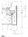
- einen Teil eines Längsschnitts durch eine vertikalachsige Wasserkraftmaschine, deren Welle mit dem Tragkopf einstückig ausgebildet ist, und individuell einstellbare Traglagersegmente aufweist, die mittels zweiarmigen Kipphebeln abgestützt sind;
- Fig.1a
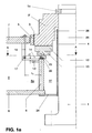
- eine mit Fig.1 vergleichbare Wasserkraftmaschine im Längsschnitt mit separatem Tragkopf;
- Fig.2
- einen Querschnitt durch durch die Maschine gemäss Fig.1 längs deren Linie AA;
- Fig.2a
- das Detail X aus Fig.2
- Fig.3
- eine vergrösserte Seitenansicht eines Kipphebels;
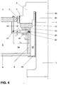
- Fig.4
- eine alternative Ausführungsform der Traglagersegment-Abstützung mit einarmigen Kipphebeln.
- In Fig.1 bzw. Fig.1a der Zeichnung sind eine Welle 1 einer vertikalachsigen Wasserkraftmaschine mit einem Tragkopf 2 einstückig ausgebildet, bzw. der Tragkopf 2' ist mit der Welle 1 zweistückig ausgeführt, wobei die Welle 1 von einem Stützring 1a getragen wird. Der Tragkopf 2 weist am Aussenumfang eine Lauffläche 3 des Führungslagers und stirnseitig eine Lauffläche 4 des Traglagers auf. Das Führungslagersegment 5 des Führungslagers stützt sich ab am Innenumfang des Lagertragsterns, von dem in Fig.1 nur der untere Ring 6, der Zugring, und der obere Ring 7, der Druckring, sowie eine die beiden Ringe 6 und 7 verbindende radiale Rippe 8 sichtbar sind.
- Die Rippen 8 sind am radial innenliegenden Ende mit einer Ausnehmung versehen. Ein Tragring 9 ist rundum mit dem vorkragenden Ende 8a aller Rippen 8 und dem unteren Ring 6 des Lagertragsterns verschweisst. Auf die radial verlaufenden Kanten der vorkragenden Enden 8a der Rippen 8 ist ein Versteifungsring 10 aufgelegt und mit diesen verschweisst.
- Die Traglagersegmente 12 liegen je auf einem Segmentteller 13 auf. Zur Höhenverstellung der Traglagersegmente 12 sind Kipphebel 14 vorgesehen. Diese sind - wie die gegenüber Fig.1 vergrösserte Darstellung gemäss Fig.3 zeigt - als zweiarmige Hebel ausgebildet. Sie besitzen keinen Drehpunkt im eigentlichen Sinn. Ihr "Drehpunkt" bildet eine zylinderabschnittförmige Materialerweiterung 15 an der Unterseite des Kipphebels 13, die auf der oberen Stirnfläche des Tragrings 9 aufliegt. Auf der Oberseite ist am radial inneren Ende des Kipphebels 14 eine kalottenförmige Materialerweiterung 16 vorgesehen, welche an der Unterseite des Segmenttellers 13 anliegt.
- Am radial aussenliegenden Ende des Kipphebels 14 ist eine horizontale Bohrung vorgesehen, in welcher ein Bolzen 17 mit einer quer zur Bolzenlängsachse verlaufenden Gewindebohrung liegt. In diese ist eine Gewindestange 18 eingeschraubt, welche durch eine Gewindebuchse 19 im oberen Ring 7 des Lagertragsterns geführt ist. Das obere Ende der Gewindestange 18 weist einen Vierkant 20 auf. Eine Kontermutter 21 dient der Sicherung. Nach Lösen der Kontermutter 21 kann durch Links- oder Rechtsdrehen der Gweindestange 18 der Kipphebel 14 auf- oder abbewegt, und damit der zugehörige Segmentteller 13 und das zugehörige Traglagersegment 12 mehr oder weniger an die Lauffläche 4 des Traglagers angepresst werden. Durch Messen der Durchbiegung des Kipphebels 14 kann jede Segmentbelastung genau ermittelt und eingestellt werden. Das Verhältnis der Hebelarme hi/ha ist dabei in weiten Grenzen frei wählbar, wobei die Länge des äusseren, längeren Hebelarms ha und dessen Querschnitt auch die Elastitizät der Tragsegmentabstützung mitbestimmt.
- Der Abstand d zwischen der Unterseite des Kipphebels 14 und der radial verlaufenden Kante des vorkragenden Endes 8a der Rippe 8 dient als leicht zu erfassendes Richtmass während der Montage der Maschine. Es lässt sich auch während des Betriebes leicht überwachen, z.B. in an sich bekannter Weise mittels kapazitiver Abstandsmessung.
- Gemäss Fig.2a sind zur seitlichen Führung der Kipphebel 14 auf der oberen Stirnfläche des Tragrings 9 paarweise Nocken 22 oder Ringsegmente 22' (in Fig.2 strichliert eingezeichnet) vorgesehen. Diese Nocken 22 oder Ringsegmente 22a verhindern ein Verschieben der Kipphebel 14 in Umfangsrichtung infolge Drehmoment. In radialer Richtung sind die Kipphebel 14 mittels paarweise angeordneter horizontal verlaufender Bolzen 23 in den Kipphebeln 14 gesichert.
- Trag- und Führungslager sind in bekannter Weise gegenüber der Welle 1, nach unten und gegen den Lagertragstern abgeschlossen. So erfolgt die Abdichtung nach unten durch einen (aus Montagegründen) zwei- oder mehrteiligen Dichtring 24, der radial aussen mit dem unteren Ring 6 verschraubt ist. Radial innen ist am Dichtring 24 das untere Ende eines die Welle umfassenden Rohres 25 befestigt. Dieses Rohr 25 endet in einer tiefen Eindrehung 26 im Tragkopf 2, in welche Eindrehung auch das Rohr 25 in Achsrichtung bis über die Lauffläche 3 des Führungslagers reicht.
- Die Abdichtung gegen den Lagertragstern hin erfolgt durch eine in Fig.1 nicht eingezeichnete Trennwand, die mit den beiden Ringen 6 und 7 und mit den Rippen 8 verschweisst ist und normalerweise eine durch einen Montagedeckel verschliessbare Montageöffnung aufweist, die gleichfalls in Fig.1 fortgelassen wurde.
- Ohne den durch die Erfindung gesteckten Rahmen zu verlassen, bieten sich eine Fülle von Ausgestaltungen des Erfindungsgegenstandes, die nachfolgend kurz skizziert werden sollen.
- Anstelle eines als zweiarmiger Hebel wirkenden Kipphebels 14 kann gemäss Fig.4 auch ein als einarmiger Hebel wirkender Kipphebel 14' verwendet werden, was jedoch den Raum zwischen Welle 1 und Tragring 9, die sogenannte Pumpenkammer 27, verkleinert.
- Wie aus Fig.2 hervorgeht, liegen die Kipphebel jeweils in der Richtung der radialen Rippen 8. Sie können jedoch auch jeweils zwischen zwei benachbarten radialen Rippen 8 angeordnet sein. Auch können pro Traglagersegment ein oder mehrere Kipphebel 14 bzw. 14' vorgesehen sein.
- Die Kipphebel 14 selbst können massiv ausgeführt sein. Vorteilhaft ist es jedoch, diese aus unter sich gleichartigen dünnen Einzelblechen zusammenzusetzen (vgl. Fig.2a), die mittels Laser-Schneidmaschinen ausgeschnitten und untereinander verschweist oder vernietet sind.
-
- 1
- Welle
- 1a
- Stützring
- 2
- Tragkopf
- 2'
- Separater Tragkopf
- 3
- Lauffläche des Führungslagers
- 4
- Lauffläche des Traglagers
- 5
- Führungslagersegmente
- 6
- Unterer Ring des Lagertragsterns (Zugring)
- 7
- Oberer Ring des Lagertragsterns (Druckring)
- 8
- radiale Rippen
- 8a
- vorkragende Enden von 8
- 9
- Tragring
- 10
- Versteifungsring
- 12
- Traglagersegmente
- 13
- Segmentteller
- 14,14'
- Kipphebel
- 14a
- äussere Kipphebelteil
- 14i
- innerer Kipphebelteil
- 15
- zylinderabschnittförmiger Vorsprung an 14
- 16
- kalottenförmiger Vorsprung an 14
- 17
- Bolzen
- 18
- Gewindestange
- 19
- Gewindebuchse
- 20
- Vierkant an 18
- 21
- Kontermutter
- 22
- paarweise angeordnete Nocken an 9
- 22a
- Ringsegmente an 9
- 23
- Bolzen in 14
- 24
- Dichtring
- 25
- Rohr
- 26
- Eindrehung in 2
- 27
- Pumpenkammer
- d
- Abstand zwischen 14 und 8a
- ha
- wirksamer Hebelarm von 14a
- hi
- wirksamer Hebelarm von 14i
Claims (5)
- Vertikalachsige Wasserkraftmaschine, mit einer in einem Lagertragstern gelagerten Welle, welche Welle einen integrierten Tragkopf (2) oder einen separaten Tragkopf (2') mit einen Laufring für ein Traglager aufweist, und Traglagersegmente (12) vorgesehen sind, die sich über Einstellelemente auf einem fest mit dem Lagertragstern (7,8) verbundenem Tragring (9) abstützen, dadurch gekennzeichnet, dass die Einstellelemente als radial verlaufende Kipphebel (14;14') ausgebildet sind, welche Kipphebel einerseits am besagten Tragring (9) und andererseits am Traglagersegment (12) angreifen, und dass der freie Hebelarm (14a) der Kipphebel (14) über Einstellmittel (18,19,20) am Lagertragstern (7) angreift.
- Wasserkraftmaschine nach Anspruch 1, dadurch gekennzeichnet, dass der Kipphebel (14) einen zweiarmigen Hebel (14a,14i) bildet, wobei der Drehpunkt des Hebels auf dem besagten Tragring liegt, der eine, kürzere Hebelarm (14i) radial innen liegt und am Traglagersegment (12) angreift und der andere, längere Hebelarm (14a) über Einstellmittel (18,19,20) am Lagertragstern (7) angreift.
- Wasserkraftmaschine nach Anspruch 1, dadurch gekennzeichnet, dass der Kipphebel (14) einen einarmigen Hebel bildet, wobei der Drehpunkt des Hebels auf dem besagten Tragring (9) liegt, der eine, kürzere Hebelarm (14i) radial innen liegt und am Traglagersegment (12) angreift und der andere, längere Hebelarm (14a) über Einstellmittel (18,19,20) am Lagertragstern (7) angreift.
- Wasserkraftmaschine nach Anspruch 2 oder 3, dadurch gekennzeichnet, dass Mittel (22,23) zur Sicherung der Kipphebel (14) ind radialer und/oder im Umfangsrichtung vorgesehen sind.
- Wasserkraftmaschine nach Anspruch 2 oder 3, dadurch gekennzeichnet, dass die Kipphebel (14) aus unter sich gleichartigen Einzelblechen zusammengesetzt sind.
Applications Claiming Priority (2)
| Application Number | Priority Date | Filing Date | Title |
|---|---|---|---|
| DE4435440 | 1994-10-04 | ||
| DE4435440A DE4435440A1 (de) | 1994-10-04 | 1994-10-04 | Vertikalachsige Wasserkraftmaschine |
Publications (3)
| Publication Number | Publication Date |
|---|---|
| EP0705974A2 true EP0705974A2 (de) | 1996-04-10 |
| EP0705974A3 EP0705974A3 (de) | 1998-03-04 |
| EP0705974B1 EP0705974B1 (de) | 2001-08-01 |
Family
ID=6529916
Family Applications (1)
| Application Number | Title | Priority Date | Filing Date |
|---|---|---|---|
| EP95810589A Expired - Lifetime EP0705974B1 (de) | 1994-10-04 | 1995-09-20 | Lagerung einer vertikalachsigen Wasserkraftmaschinenwelle |
Country Status (10)
| Country | Link |
|---|---|
| US (1) | US5653578A (de) |
| EP (1) | EP0705974B1 (de) |
| CN (1) | CN1077231C (de) |
| AT (1) | ATE203801T1 (de) |
| BR (1) | BR9503067A (de) |
| CA (1) | CA2148568C (de) |
| DE (2) | DE4435440A1 (de) |
| ES (1) | ES2161849T3 (de) |
| NO (1) | NO321313B1 (de) |
| RU (1) | RU2146773C1 (de) |
Families Citing this family (2)
| Publication number | Priority date | Publication date | Assignee | Title |
|---|---|---|---|---|
| RU2194213C2 (ru) * | 2000-05-15 | 2002-12-10 | Гроздов Борис Николаевич | Цилиндрическая водогрейная установка (варианты) и металлический кольцевой коллектор |
| CN103410874A (zh) * | 2013-08-20 | 2013-11-27 | 海安金太阳纺织有限公司 | 机床轴承杠杆结构装置 |
Citations (1)
| Publication number | Priority date | Publication date | Assignee | Title |
|---|---|---|---|---|
| EP0586861A1 (de) | 1992-09-05 | 1994-03-16 | Asea Brown Boveri Ag | Kombiniertes Trag- und Führungslager einer vertikalachsigen Wasserkraftmaschine |
Family Cites Families (10)
| Publication number | Priority date | Publication date | Assignee | Title |
|---|---|---|---|---|
| US1441614A (en) * | 1918-06-29 | 1923-01-09 | Albert Kingsbury | Bearing |
| US3276742A (en) * | 1963-11-05 | 1966-10-04 | Hitachi Ltd | Vertical shaft kaplan water turbines |
| DE2440549A1 (de) * | 1974-08-21 | 1976-03-04 | Siemens Ag | Maschinensatz mit senkrechter welle, insbesondere wasserkraftmaschinensatz |
| CH604034A5 (de) * | 1975-07-09 | 1978-08-31 | Sulzer Ag | |
| US4073549A (en) * | 1975-12-02 | 1978-02-14 | Escher Wyss Limited | Hydrostatic supporting device |
| DE2710706C2 (de) * | 1977-03-09 | 1982-04-08 | Siemens AG, 1000 Berlin und 8000 München | Radiales Führungslager mit Lagersegmenten für Maschinen mit vertikaler Welle |
| JPS5776315A (en) * | 1980-10-29 | 1982-05-13 | Hitachi Ltd | Thrust bearing device |
| SU1341371A1 (ru) * | 1985-08-07 | 1987-09-30 | Производственное Объединение Турбостроения "Ленинградский Металлический Завод" | Направл ющий подшипник вала гидромашины |
| CA1250615A (en) * | 1985-09-13 | 1989-02-28 | Canadian General Electric Company Limited | Hydraulically supported thrust bearings |
| JPH01161790A (ja) * | 1987-12-17 | 1989-06-26 | Nec Corp | 圧電アクチュエータ用変位拡大機構 |
-
1994
- 1994-10-04 DE DE4435440A patent/DE4435440A1/de not_active Withdrawn
-
1995
- 1995-05-03 CA CA002148568A patent/CA2148568C/en not_active Expired - Fee Related
- 1995-07-03 BR BR9503067A patent/BR9503067A/pt not_active IP Right Cessation
- 1995-09-01 US US08/522,923 patent/US5653578A/en not_active Expired - Lifetime
- 1995-09-20 ES ES95810589T patent/ES2161849T3/es not_active Expired - Lifetime
- 1995-09-20 AT AT95810589T patent/ATE203801T1/de active
- 1995-09-20 DE DE59509464T patent/DE59509464D1/de not_active Expired - Lifetime
- 1995-09-20 EP EP95810589A patent/EP0705974B1/de not_active Expired - Lifetime
- 1995-09-27 NO NO19953818A patent/NO321313B1/no not_active IP Right Cessation
- 1995-09-27 RU RU95116652/06A patent/RU2146773C1/ru not_active IP Right Cessation
- 1995-09-29 CN CN95117236A patent/CN1077231C/zh not_active Expired - Fee Related
Patent Citations (1)
| Publication number | Priority date | Publication date | Assignee | Title |
|---|---|---|---|---|
| EP0586861A1 (de) | 1992-09-05 | 1994-03-16 | Asea Brown Boveri Ag | Kombiniertes Trag- und Führungslager einer vertikalachsigen Wasserkraftmaschine |
Also Published As
| Publication number | Publication date |
|---|---|
| NO953818D0 (no) | 1995-09-27 |
| EP0705974B1 (de) | 2001-08-01 |
| CN1131231A (zh) | 1996-09-18 |
| CN1077231C (zh) | 2002-01-02 |
| ES2161849T3 (es) | 2001-12-16 |
| ATE203801T1 (de) | 2001-08-15 |
| DE59509464D1 (de) | 2001-09-06 |
| US5653578A (en) | 1997-08-05 |
| RU2146773C1 (ru) | 2000-03-20 |
| CA2148568C (en) | 2005-01-11 |
| EP0705974A3 (de) | 1998-03-04 |
| BR9503067A (pt) | 1997-05-27 |
| CA2148568A1 (en) | 1996-04-05 |
| NO321313B1 (no) | 2006-04-24 |
| DE4435440A1 (de) | 1996-04-11 |
| NO953818L (no) | 1996-04-09 |
Similar Documents
| Publication | Publication Date | Title |
|---|---|---|
| DE10324621A1 (de) | Elektrische Maschine | |
| DE2110485B2 (de) | Vorrichtung zum Herstellen von Rohren mit schraubenförmigen Rippen auf der Außenwandung | |
| EP1004525A1 (de) | Zellenradschleuse mit Ausziehvorrichtung | |
| EP0283980B1 (de) | Meisseldirektantrieb für Tiefbohrwerkzeuge | |
| EP0705974B1 (de) | Lagerung einer vertikalachsigen Wasserkraftmaschinenwelle | |
| DE69118074T2 (de) | Dynamisches Drucklager für eine Röntgenröhre mit Drehanode | |
| EP3650590A1 (de) | Spinnmaschine sowie spindelbank | |
| EP0586861B1 (de) | Kombiniertes Trag- und Führungslager einer vertikalachsigen Wasserkraftmaschine | |
| EP0209799B1 (de) | Einrichtung zum radial beweglichen Befestigen eines Spindellagergehäuses einer Spinn- oder Zwirnspindel an einer Spindelbank | |
| DE19842957A1 (de) | Führungsbüchse und längenverstellbare Säule mit Führungsbüchse | |
| WO2013114190A1 (de) | Vorrichtung zur erfassung von kräftebelastungen einer stützstruktur | |
| DE2515200C2 (de) | Dichtvorrichtung für die Lager der Tragwellen von fliegend und auswechselbar angeordneten Walzscheiben | |
| DE2710706A1 (de) | Radiales fuehrungslager mit lagersegmenten fuer maschinen mit vertikaler welle | |
| DE2421260A1 (de) | Wellenanordnung zum befestigen eines schleifsteins in zellulose-schleifmaschinen | |
| DE2459236C3 (de) | Traganordnung für die Wellenlagerung einer vertikalen, elektrischen Maschine | |
| DE2801920A1 (de) | Lagerstuetze | |
| DE202007013550U1 (de) | Einstellbare Richtvorrichtung | |
| DE102006035915A1 (de) | Hubeinrichtung | |
| EP0256147A1 (de) | Scheibenbrecher | |
| DE2558562A1 (de) | Hochdruck-membranventil | |
| DE3138571C2 (de) | Kopierschleifmaschine | |
| DE19525830A1 (de) | Rohrturbinenanlage | |
| DE4242909C2 (de) | Hohlbohrkrone mit Schneiden | |
| AT391167B (de) | Stroemungsmaschine, wie wasserturbine, pumpe oder pumpenturbine | |
| DE19708255B4 (de) | Lagerstelle für ein Laufrad |
Legal Events
| Date | Code | Title | Description |
|---|---|---|---|
| PUAI | Public reference made under article 153(3) epc to a published international application that has entered the european phase |
Free format text: ORIGINAL CODE: 0009012 |
|
| AK | Designated contracting states |
Kind code of ref document: A2 Designated state(s): AT DE ES FR GB IT |
|
| RAP1 | Party data changed (applicant data changed or rights of an application transferred) |
Owner name: ASEA BROWN BOVERI AG |
|
| PUAL | Search report despatched |
Free format text: ORIGINAL CODE: 0009013 |
|
| AK | Designated contracting states |
Kind code of ref document: A3 Designated state(s): AT DE ES FR GB IT |
|
| 17P | Request for examination filed |
Effective date: 19980727 |
|
| 17Q | First examination report despatched |
Effective date: 19991104 |
|
| RAP1 | Party data changed (applicant data changed or rights of an application transferred) |
Owner name: ABB ALSTOM POWER (SCHWEIZ) AG |
|
| GRAG | Despatch of communication of intention to grant |
Free format text: ORIGINAL CODE: EPIDOS AGRA |
|
| GRAG | Despatch of communication of intention to grant |
Free format text: ORIGINAL CODE: EPIDOS AGRA |
|
| GRAH | Despatch of communication of intention to grant a patent |
Free format text: ORIGINAL CODE: EPIDOS IGRA |
|
| RAP1 | Party data changed (applicant data changed or rights of an application transferred) |
Owner name: ALSTOM POWER (SCHWEIZ) AG |
|
| GRAH | Despatch of communication of intention to grant a patent |
Free format text: ORIGINAL CODE: EPIDOS IGRA |
|
| RAP1 | Party data changed (applicant data changed or rights of an application transferred) |
Owner name: ALSTOM (SCHWEIZ) AG |
|
| GRAA | (expected) grant |
Free format text: ORIGINAL CODE: 0009210 |
|
| AK | Designated contracting states |
Kind code of ref document: B1 Designated state(s): AT DE ES FR GB IT |
|
| REF | Corresponds to: |
Ref document number: 203801 Country of ref document: AT Date of ref document: 20010815 Kind code of ref document: T |
|
| REF | Corresponds to: |
Ref document number: 59509464 Country of ref document: DE Date of ref document: 20010906 |
|
| GBT | Gb: translation of ep patent filed (gb section 77(6)(a)/1977) |
Effective date: 20011101 |
|
| REG | Reference to a national code |
Ref country code: ES Ref legal event code: FG2A Ref document number: 2161849 Country of ref document: ES Kind code of ref document: T3 |
|
| ET | Fr: translation filed | ||
| REG | Reference to a national code |
Ref country code: GB Ref legal event code: IF02 |
|
| PLBE | No opposition filed within time limit |
Free format text: ORIGINAL CODE: 0009261 |
|
| STAA | Information on the status of an ep patent application or granted ep patent |
Free format text: STATUS: NO OPPOSITION FILED WITHIN TIME LIMIT |
|
| 26N | No opposition filed | ||
| PGFP | Annual fee paid to national office [announced via postgrant information from national office to epo] |
Ref country code: DE Payment date: 20100930 Year of fee payment: 16 |
|
| PGFP | Annual fee paid to national office [announced via postgrant information from national office to epo] |
Ref country code: ES Payment date: 20110915 Year of fee payment: 17 Ref country code: FR Payment date: 20110901 Year of fee payment: 17 Ref country code: AT Payment date: 20110825 Year of fee payment: 17 Ref country code: GB Payment date: 20110826 Year of fee payment: 17 |
|
| PGFP | Annual fee paid to national office [announced via postgrant information from national office to epo] |
Ref country code: IT Payment date: 20110919 Year of fee payment: 17 |
|
| REG | Reference to a national code |
Ref country code: AT Ref legal event code: MM01 Ref document number: 203801 Country of ref document: AT Kind code of ref document: T Effective date: 20120920 |
|
| GBPC | Gb: european patent ceased through non-payment of renewal fee |
Effective date: 20120920 |
|
| REG | Reference to a national code |
Ref country code: FR Ref legal event code: ST Effective date: 20130531 |
|
| PG25 | Lapsed in a contracting state [announced via postgrant information from national office to epo] |
Ref country code: GB Free format text: LAPSE BECAUSE OF NON-PAYMENT OF DUE FEES Effective date: 20120920 Ref country code: DE Free format text: LAPSE BECAUSE OF NON-PAYMENT OF DUE FEES Effective date: 20130403 Ref country code: AT Free format text: LAPSE BECAUSE OF NON-PAYMENT OF DUE FEES Effective date: 20120920 |
|
| PG25 | Lapsed in a contracting state [announced via postgrant information from national office to epo] |
Ref country code: IT Free format text: LAPSE BECAUSE OF NON-PAYMENT OF DUE FEES Effective date: 20120920 Ref country code: FR Free format text: LAPSE BECAUSE OF NON-PAYMENT OF DUE FEES Effective date: 20121001 |
|
| REG | Reference to a national code |
Ref country code: DE Ref legal event code: R119 Ref document number: 59509464 Country of ref document: DE Effective date: 20130403 |
|
| REG | Reference to a national code |
Ref country code: ES Ref legal event code: FD2A Effective date: 20131022 |
|
| PG25 | Lapsed in a contracting state [announced via postgrant information from national office to epo] |
Ref country code: ES Free format text: LAPSE BECAUSE OF NON-PAYMENT OF DUE FEES Effective date: 20120921 |