EP0705974A2 - Support d'arbre vertical pour turbine à eau - Google Patents
Support d'arbre vertical pour turbine à eau Download PDFInfo
- Publication number
- EP0705974A2 EP0705974A2 EP95810589A EP95810589A EP0705974A2 EP 0705974 A2 EP0705974 A2 EP 0705974A2 EP 95810589 A EP95810589 A EP 95810589A EP 95810589 A EP95810589 A EP 95810589A EP 0705974 A2 EP0705974 A2 EP 0705974A2
- Authority
- EP
- European Patent Office
- Prior art keywords
- support
- bearing
- ring
- star
- rocker
- Prior art date
- Legal status (The legal status is an assumption and is not a legal conclusion. Google has not performed a legal analysis and makes no representation as to the accuracy of the status listed.)
- Granted
Links
Images

Classifications
-
- F—MECHANICAL ENGINEERING; LIGHTING; HEATING; WEAPONS; BLASTING
- F03—MACHINES OR ENGINES FOR LIQUIDS; WIND, SPRING, OR WEIGHT MOTORS; PRODUCING MECHANICAL POWER OR A REACTIVE PROPULSIVE THRUST, NOT OTHERWISE PROVIDED FOR
- F03B—MACHINES OR ENGINES FOR LIQUIDS
- F03B11/00—Parts or details not provided for in, or of interest apart from, the preceding groups, e.g. wear-protection couplings, between turbine and generator
- F03B11/06—Bearing arrangements
- F03B11/063—Arrangements for balancing axial thrust
- F03B11/066—Arrangements for balancing axial thrust in vertical axis machines
-
- F—MECHANICAL ENGINEERING; LIGHTING; HEATING; WEAPONS; BLASTING
- F16—ENGINEERING ELEMENTS AND UNITS; GENERAL MEASURES FOR PRODUCING AND MAINTAINING EFFECTIVE FUNCTIONING OF MACHINES OR INSTALLATIONS; THERMAL INSULATION IN GENERAL
- F16C—SHAFTS; FLEXIBLE SHAFTS; ELEMENTS OR CRANKSHAFT MECHANISMS; ROTARY BODIES OTHER THAN GEARING ELEMENTS; BEARINGS
- F16C17/00—Sliding-contact bearings for exclusively rotary movement
- F16C17/04—Sliding-contact bearings for exclusively rotary movement for axial load only
- F16C17/06—Sliding-contact bearings for exclusively rotary movement for axial load only with tiltably-supported segments, e.g. Michell bearings
-
- F—MECHANICAL ENGINEERING; LIGHTING; HEATING; WEAPONS; BLASTING
- F16—ENGINEERING ELEMENTS AND UNITS; GENERAL MEASURES FOR PRODUCING AND MAINTAINING EFFECTIVE FUNCTIONING OF MACHINES OR INSTALLATIONS; THERMAL INSULATION IN GENERAL
- F16C—SHAFTS; FLEXIBLE SHAFTS; ELEMENTS OR CRANKSHAFT MECHANISMS; ROTARY BODIES OTHER THAN GEARING ELEMENTS; BEARINGS
- F16C41/00—Other accessories, e.g. devices integrated in the bearing not relating to the bearing function as such
- F16C41/02—Arrangements for equalising the load on a plurality of bearings or their elements
-
- Y—GENERAL TAGGING OF NEW TECHNOLOGICAL DEVELOPMENTS; GENERAL TAGGING OF CROSS-SECTIONAL TECHNOLOGIES SPANNING OVER SEVERAL SECTIONS OF THE IPC; TECHNICAL SUBJECTS COVERED BY FORMER USPC CROSS-REFERENCE ART COLLECTIONS [XRACs] AND DIGESTS
- Y02—TECHNOLOGIES OR APPLICATIONS FOR MITIGATION OR ADAPTATION AGAINST CLIMATE CHANGE
- Y02E—REDUCTION OF GREENHOUSE GAS [GHG] EMISSIONS, RELATED TO ENERGY GENERATION, TRANSMISSION OR DISTRIBUTION
- Y02E10/00—Energy generation through renewable energy sources
- Y02E10/20—Hydro energy
Definitions
- the invention relates to a vertical-axis hydropower machine, with a shaft mounted in a bearing support star, which shaft has a race for a support bearing, and support bearing segments are provided which are supported by adjusting elements on a support ring fixedly connected to the bearing support star.
- a vertical-axis hydropower machine of this type is known, for example, from EP-0 586 861 A1.
- the invention has for its object to provide a vertical-axis hydropower machine, the support bearing segments are individually adjustable, and which allows a small overall height with optimal accessibility of the adjusting elements.
- adjusting elements are designed as radially extending rocker arms which act on the one hand on said support ring and on the other hand on the support bearing segment, and in that the free lever arm acts on the bearing support star via adjusting means.
- the rocker arms can act either as one- or two-armed levers, with the shorter lever arm coming radially inwards and between the said support ring and the support bearing segment.
- the rocker arms take up little space in the axial direction. Your space requirement in this dimension is comparable to known elastic segment support arrangements with spring plates or feather beds. Depending on the geometry of the rocker arms, for example the cross section and / or length of the longer lever arm, these are elastic transversely to their longitudinal direction. This also makes the support of the support bearing segments resilient. It is possible to calculate the bending of the rocker arms (bending beam) under load very precisely. It can easily be measured during assembly. Monitoring the deflection of the "beam” is also easily possible during operation, for example with known capacitive distance sensors.
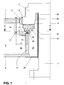
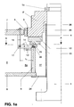
- a shaft 1 of a vertical-axis hydropower machine is formed in one piece with a support head 2, or the support head 2 'is made in two pieces with the shaft 1, the shaft 1 being supported by a support ring 1a.
- the support head 2 has a on the outer circumference Running surface 3 of the guide bearing and on the end face a running surface 4 of the support bearing.
- the guide bearing segment 5 of the guide bearing is supported on the inner circumference of the bearing support star, of which only the lower ring 6, the pull ring, and the upper ring 7, the pressure ring, and a radial rib 8 connecting the two rings 6 and 7, are visible in FIG are.
- the ribs 8 are provided with a recess at the radially inner end.
- a support ring 9 is welded all around with the projecting end 8a of all the ribs 8 and the lower ring 6 of the bearing support star.
- a stiffening ring 10 is placed on the radially extending edges of the projecting ends 8a of the ribs 8 and welded to them.
- the support bearing segments 12 each rest on a segment plate 13.
- Rocker arms 14 are provided for height adjustment of the support bearing segments 12. These are designed as two-armed levers, as the enlarged representation according to FIG. 3 shows compared to FIG. They have no pivot point in the real sense. Its "fulcrum” forms a cylindrical section-shaped material extension 15 on the underside of the rocker arm 13, which rests on the upper end face of the support ring 9. On the upper side, a dome-shaped material extension 16 is provided at the radially inner end of the rocker arm 14, which lies against the underside of the segment plate 13.
- rocker arm 14 At the radially outer end of the rocker arm 14 there is a horizontal bore in which a bolt 17 is located with a threaded bore extending transversely to the longitudinal axis of the bolt. A threaded rod 18 is screwed into this, which is guided through a threaded bushing 19 in the upper ring 7 of the bearing support star. The upper end of the threaded rod 18 has a square 20. A lock nut 21 is used for securing. After loosening the lock nut 21, the rocker arm 14 can be moved up or down by turning the threaded rod 18 to the left or right, and thus the associated segment plate 13 and the associated support bearing segment 12 more or less to the Tread 4 of the support bearing are pressed.
- each segment load can be precisely determined and set.
- the ratio of the lever arms h i / h a can be freely selected within wide limits, the length of the outer, longer lever arm h a and its cross-section also determining the elasticity of the supporting segment support.
- the distance d between the underside of the rocker arm 14 and the radially running edge of the projecting end 8a of the rib 8 serves as an easy-to-measure standard dimension during the assembly of the machine. It can also be easily monitored during operation, e.g. in a manner known per se by means of capacitive distance measurement.
- cams 22 or ring segments 22 ' are provided in pairs for lateral guidance of the rocker arms 14 on the upper end face of the support ring 9. These cams 22 or ring segments 22a prevent displacement of the rocker arms 14 in the circumferential direction due to torque.
- the rocker arms 14 are secured in the radial direction in the rocker arms 14 by means of horizontally extending bolts 23 arranged in pairs.
- the seal against the bearing support star is provided by a partition wall (not shown in FIG. 1), which is connected to the two Rings 6 and 7 and is welded to the ribs 8 and normally has a mounting opening which can be closed by a mounting cover and which has likewise been omitted in FIG. 1.
- a rocker arm 14 acting as a two-armed lever
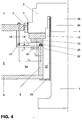
- a rocker arm 14 'acting as a one-armed lever can also be used according to FIG. 4, but this reduces the space between shaft 1 and support ring 9, the so-called pump chamber 27.
- the rocker arms each lie in the direction of the radial ribs 8. However, they can also be arranged between two adjacent radial ribs 8. One or more rocker arms 14 or 14 'can also be provided for each support bearing segment.
- the rocker arm 14 itself can be solid. However, it is advantageous to assemble them from thin individual sheets of the same type (see FIG. 2a), which are cut out by means of laser cutting machines and welded or riveted to one another.
Landscapes
- Engineering & Computer Science (AREA)
- General Engineering & Computer Science (AREA)
- Mechanical Engineering (AREA)
- Chemical & Material Sciences (AREA)
- Combustion & Propulsion (AREA)
- Hydraulic Turbines (AREA)
- Support Of The Bearing (AREA)
- Sliding-Contact Bearings (AREA)
- Hydraulic Motors (AREA)
- Applications Or Details Of Rotary Compressors (AREA)
- Reciprocating Pumps (AREA)
- Forklifts And Lifting Vehicles (AREA)
- Jib Cranes (AREA)
Applications Claiming Priority (2)
| Application Number | Priority Date | Filing Date | Title |
|---|---|---|---|
| DE4435440 | 1994-10-04 | ||
| DE4435440A DE4435440A1 (de) | 1994-10-04 | 1994-10-04 | Vertikalachsige Wasserkraftmaschine |
Publications (3)
| Publication Number | Publication Date |
|---|---|
| EP0705974A2 true EP0705974A2 (fr) | 1996-04-10 |
| EP0705974A3 EP0705974A3 (fr) | 1998-03-04 |
| EP0705974B1 EP0705974B1 (fr) | 2001-08-01 |
Family
ID=6529916
Family Applications (1)
| Application Number | Title | Priority Date | Filing Date |
|---|---|---|---|
| EP95810589A Expired - Lifetime EP0705974B1 (fr) | 1994-10-04 | 1995-09-20 | Support d'arbre vertical pour turbine à eau |
Country Status (10)
| Country | Link |
|---|---|
| US (1) | US5653578A (fr) |
| EP (1) | EP0705974B1 (fr) |
| CN (1) | CN1077231C (fr) |
| AT (1) | ATE203801T1 (fr) |
| BR (1) | BR9503067A (fr) |
| CA (1) | CA2148568C (fr) |
| DE (2) | DE4435440A1 (fr) |
| ES (1) | ES2161849T3 (fr) |
| NO (1) | NO321313B1 (fr) |
| RU (1) | RU2146773C1 (fr) |
Families Citing this family (2)
| Publication number | Priority date | Publication date | Assignee | Title |
|---|---|---|---|---|
| RU2194213C2 (ru) * | 2000-05-15 | 2002-12-10 | Гроздов Борис Николаевич | Цилиндрическая водогрейная установка (варианты) и металлический кольцевой коллектор |
| CN103410874A (zh) * | 2013-08-20 | 2013-11-27 | 海安金太阳纺织有限公司 | 机床轴承杠杆结构装置 |
Citations (1)
| Publication number | Priority date | Publication date | Assignee | Title |
|---|---|---|---|---|
| EP0586861A1 (fr) | 1992-09-05 | 1994-03-16 | Asea Brown Boveri Ag | Palier combinée radial-axial pour machine hydroélectrique à axe vertical |
Family Cites Families (10)
| Publication number | Priority date | Publication date | Assignee | Title |
|---|---|---|---|---|
| US1441614A (en) * | 1918-06-29 | 1923-01-09 | Albert Kingsbury | Bearing |
| US3276742A (en) * | 1963-11-05 | 1966-10-04 | Hitachi Ltd | Vertical shaft kaplan water turbines |
| DE2440549A1 (de) * | 1974-08-21 | 1976-03-04 | Siemens Ag | Maschinensatz mit senkrechter welle, insbesondere wasserkraftmaschinensatz |
| CH604034A5 (fr) * | 1975-07-09 | 1978-08-31 | Sulzer Ag | |
| US4073549A (en) * | 1975-12-02 | 1978-02-14 | Escher Wyss Limited | Hydrostatic supporting device |
| DE2710706C2 (de) * | 1977-03-09 | 1982-04-08 | Siemens AG, 1000 Berlin und 8000 München | Radiales Führungslager mit Lagersegmenten für Maschinen mit vertikaler Welle |
| JPS5776315A (en) * | 1980-10-29 | 1982-05-13 | Hitachi Ltd | Thrust bearing device |
| SU1341371A1 (ru) * | 1985-08-07 | 1987-09-30 | Производственное Объединение Турбостроения "Ленинградский Металлический Завод" | Направл ющий подшипник вала гидромашины |
| CA1250615A (fr) * | 1985-09-13 | 1989-02-28 | Canadian General Electric Company Limited | Roulements de butee a support hydraulique |
| JPH01161790A (ja) * | 1987-12-17 | 1989-06-26 | Nec Corp | 圧電アクチュエータ用変位拡大機構 |
-
1994
- 1994-10-04 DE DE4435440A patent/DE4435440A1/de not_active Withdrawn
-
1995
- 1995-05-03 CA CA002148568A patent/CA2148568C/fr not_active Expired - Fee Related
- 1995-07-03 BR BR9503067A patent/BR9503067A/pt not_active IP Right Cessation
- 1995-09-01 US US08/522,923 patent/US5653578A/en not_active Expired - Lifetime
- 1995-09-20 ES ES95810589T patent/ES2161849T3/es not_active Expired - Lifetime
- 1995-09-20 AT AT95810589T patent/ATE203801T1/de active
- 1995-09-20 DE DE59509464T patent/DE59509464D1/de not_active Expired - Lifetime
- 1995-09-20 EP EP95810589A patent/EP0705974B1/fr not_active Expired - Lifetime
- 1995-09-27 NO NO19953818A patent/NO321313B1/no not_active IP Right Cessation
- 1995-09-27 RU RU95116652/06A patent/RU2146773C1/ru not_active IP Right Cessation
- 1995-09-29 CN CN95117236A patent/CN1077231C/zh not_active Expired - Fee Related
Patent Citations (1)
| Publication number | Priority date | Publication date | Assignee | Title |
|---|---|---|---|---|
| EP0586861A1 (fr) | 1992-09-05 | 1994-03-16 | Asea Brown Boveri Ag | Palier combinée radial-axial pour machine hydroélectrique à axe vertical |
Also Published As
| Publication number | Publication date |
|---|---|
| NO953818D0 (no) | 1995-09-27 |
| EP0705974B1 (fr) | 2001-08-01 |
| CN1131231A (zh) | 1996-09-18 |
| CN1077231C (zh) | 2002-01-02 |
| ES2161849T3 (es) | 2001-12-16 |
| ATE203801T1 (de) | 2001-08-15 |
| DE59509464D1 (de) | 2001-09-06 |
| US5653578A (en) | 1997-08-05 |
| RU2146773C1 (ru) | 2000-03-20 |
| CA2148568C (fr) | 2005-01-11 |
| EP0705974A3 (fr) | 1998-03-04 |
| BR9503067A (pt) | 1997-05-27 |
| CA2148568A1 (fr) | 1996-04-05 |
| NO321313B1 (no) | 2006-04-24 |
| DE4435440A1 (de) | 1996-04-11 |
| NO953818L (no) | 1996-04-09 |
Similar Documents
| Publication | Publication Date | Title |
|---|---|---|
| DE10324621A1 (de) | Elektrische Maschine | |
| DE2110485B2 (de) | Vorrichtung zum Herstellen von Rohren mit schraubenförmigen Rippen auf der Außenwandung | |
| EP1004525A1 (fr) | Vanne à roue cellulaire avec système d'extraction | |
| EP0283980B1 (fr) | Entraînement direct de trépan pour outil de forage profond | |
| EP0705974B1 (fr) | Support d'arbre vertical pour turbine à eau | |
| DE69118074T2 (de) | Dynamisches Drucklager für eine Röntgenröhre mit Drehanode | |
| EP3650590A1 (fr) | Métier à filer ainsi que traverse porte-broches | |
| EP0586861B1 (fr) | Palier combinée radial-axial pour machine hydroélectrique à axe vertical | |
| EP0209799B1 (fr) | Dispositif de fixation radialement mobile d'une boîte de palier d'une broche à filer ou à retordre sur un banc à broches | |
| DE19842957A1 (de) | Führungsbüchse und längenverstellbare Säule mit Führungsbüchse | |
| WO2013114190A1 (fr) | Dispositif de détermination de contraintes exercées sur une structure de support | |
| DE2515200C2 (de) | Dichtvorrichtung für die Lager der Tragwellen von fliegend und auswechselbar angeordneten Walzscheiben | |
| DE2710706A1 (de) | Radiales fuehrungslager mit lagersegmenten fuer maschinen mit vertikaler welle | |
| DE2421260A1 (de) | Wellenanordnung zum befestigen eines schleifsteins in zellulose-schleifmaschinen | |
| DE2459236C3 (de) | Traganordnung für die Wellenlagerung einer vertikalen, elektrischen Maschine | |
| DE2801920A1 (de) | Lagerstuetze | |
| DE202007013550U1 (de) | Einstellbare Richtvorrichtung | |
| DE102006035915A1 (de) | Hubeinrichtung | |
| EP0256147A1 (fr) | Broyeur à disques | |
| DE2558562A1 (de) | Hochdruck-membranventil | |
| DE3138571C2 (de) | Kopierschleifmaschine | |
| DE19525830A1 (de) | Rohrturbinenanlage | |
| DE4242909C2 (de) | Hohlbohrkrone mit Schneiden | |
| AT391167B (de) | Stroemungsmaschine, wie wasserturbine, pumpe oder pumpenturbine | |
| DE19708255B4 (de) | Lagerstelle für ein Laufrad |
Legal Events
| Date | Code | Title | Description |
|---|---|---|---|
| PUAI | Public reference made under article 153(3) epc to a published international application that has entered the european phase |
Free format text: ORIGINAL CODE: 0009012 |
|
| AK | Designated contracting states |
Kind code of ref document: A2 Designated state(s): AT DE ES FR GB IT |
|
| RAP1 | Party data changed (applicant data changed or rights of an application transferred) |
Owner name: ASEA BROWN BOVERI AG |
|
| PUAL | Search report despatched |
Free format text: ORIGINAL CODE: 0009013 |
|
| AK | Designated contracting states |
Kind code of ref document: A3 Designated state(s): AT DE ES FR GB IT |
|
| 17P | Request for examination filed |
Effective date: 19980727 |
|
| 17Q | First examination report despatched |
Effective date: 19991104 |
|
| RAP1 | Party data changed (applicant data changed or rights of an application transferred) |
Owner name: ABB ALSTOM POWER (SCHWEIZ) AG |
|
| GRAG | Despatch of communication of intention to grant |
Free format text: ORIGINAL CODE: EPIDOS AGRA |
|
| GRAG | Despatch of communication of intention to grant |
Free format text: ORIGINAL CODE: EPIDOS AGRA |
|
| GRAH | Despatch of communication of intention to grant a patent |
Free format text: ORIGINAL CODE: EPIDOS IGRA |
|
| RAP1 | Party data changed (applicant data changed or rights of an application transferred) |
Owner name: ALSTOM POWER (SCHWEIZ) AG |
|
| GRAH | Despatch of communication of intention to grant a patent |
Free format text: ORIGINAL CODE: EPIDOS IGRA |
|
| RAP1 | Party data changed (applicant data changed or rights of an application transferred) |
Owner name: ALSTOM (SCHWEIZ) AG |
|
| GRAA | (expected) grant |
Free format text: ORIGINAL CODE: 0009210 |
|
| AK | Designated contracting states |
Kind code of ref document: B1 Designated state(s): AT DE ES FR GB IT |
|
| REF | Corresponds to: |
Ref document number: 203801 Country of ref document: AT Date of ref document: 20010815 Kind code of ref document: T |
|
| REF | Corresponds to: |
Ref document number: 59509464 Country of ref document: DE Date of ref document: 20010906 |
|
| GBT | Gb: translation of ep patent filed (gb section 77(6)(a)/1977) |
Effective date: 20011101 |
|
| REG | Reference to a national code |
Ref country code: ES Ref legal event code: FG2A Ref document number: 2161849 Country of ref document: ES Kind code of ref document: T3 |
|
| ET | Fr: translation filed | ||
| REG | Reference to a national code |
Ref country code: GB Ref legal event code: IF02 |
|
| PLBE | No opposition filed within time limit |
Free format text: ORIGINAL CODE: 0009261 |
|
| STAA | Information on the status of an ep patent application or granted ep patent |
Free format text: STATUS: NO OPPOSITION FILED WITHIN TIME LIMIT |
|
| 26N | No opposition filed | ||
| PGFP | Annual fee paid to national office [announced via postgrant information from national office to epo] |
Ref country code: DE Payment date: 20100930 Year of fee payment: 16 |
|
| PGFP | Annual fee paid to national office [announced via postgrant information from national office to epo] |
Ref country code: ES Payment date: 20110915 Year of fee payment: 17 Ref country code: FR Payment date: 20110901 Year of fee payment: 17 Ref country code: AT Payment date: 20110825 Year of fee payment: 17 Ref country code: GB Payment date: 20110826 Year of fee payment: 17 |
|
| PGFP | Annual fee paid to national office [announced via postgrant information from national office to epo] |
Ref country code: IT Payment date: 20110919 Year of fee payment: 17 |
|
| REG | Reference to a national code |
Ref country code: AT Ref legal event code: MM01 Ref document number: 203801 Country of ref document: AT Kind code of ref document: T Effective date: 20120920 |
|
| GBPC | Gb: european patent ceased through non-payment of renewal fee |
Effective date: 20120920 |
|
| REG | Reference to a national code |
Ref country code: FR Ref legal event code: ST Effective date: 20130531 |
|
| PG25 | Lapsed in a contracting state [announced via postgrant information from national office to epo] |
Ref country code: GB Free format text: LAPSE BECAUSE OF NON-PAYMENT OF DUE FEES Effective date: 20120920 Ref country code: DE Free format text: LAPSE BECAUSE OF NON-PAYMENT OF DUE FEES Effective date: 20130403 Ref country code: AT Free format text: LAPSE BECAUSE OF NON-PAYMENT OF DUE FEES Effective date: 20120920 |
|
| PG25 | Lapsed in a contracting state [announced via postgrant information from national office to epo] |
Ref country code: IT Free format text: LAPSE BECAUSE OF NON-PAYMENT OF DUE FEES Effective date: 20120920 Ref country code: FR Free format text: LAPSE BECAUSE OF NON-PAYMENT OF DUE FEES Effective date: 20121001 |
|
| REG | Reference to a national code |
Ref country code: DE Ref legal event code: R119 Ref document number: 59509464 Country of ref document: DE Effective date: 20130403 |
|
| REG | Reference to a national code |
Ref country code: ES Ref legal event code: FD2A Effective date: 20131022 |
|
| PG25 | Lapsed in a contracting state [announced via postgrant information from national office to epo] |
Ref country code: ES Free format text: LAPSE BECAUSE OF NON-PAYMENT OF DUE FEES Effective date: 20120921 |