EP0706029A1 - Kreiselsystem für Drallgeschoss - Google Patents
Kreiselsystem für Drallgeschoss Download PDFInfo
- Publication number
- EP0706029A1 EP0706029A1 EP95402186A EP95402186A EP0706029A1 EP 0706029 A1 EP0706029 A1 EP 0706029A1 EP 95402186 A EP95402186 A EP 95402186A EP 95402186 A EP95402186 A EP 95402186A EP 0706029 A1 EP0706029 A1 EP 0706029A1
- Authority
- EP
- European Patent Office
- Prior art keywords
- axis
- gyroscopic system
- lines
- router
- rotation
- Prior art date
- Legal status (The legal status is an assumption and is not a legal conclusion. Google has not performed a legal analysis and makes no representation as to the accuracy of the status listed.)
- Granted
Links
- 238000009987 spinning Methods 0.000 title abstract description 4
- 238000001514 detection method Methods 0.000 claims description 13
- 238000002310 reflectometry Methods 0.000 claims description 5
- 230000003247 decreasing effect Effects 0.000 claims description 3
- 230000002093 peripheral effect Effects 0.000 claims description 3
- 229910000831 Steel Inorganic materials 0.000 abstract description 2
- 239000010959 steel Substances 0.000 abstract description 2
- XAGFODPZIPBFFR-UHFFFAOYSA-N aluminium Chemical compound [Al] XAGFODPZIPBFFR-UHFFFAOYSA-N 0.000 abstract 1
- 229910052782 aluminium Inorganic materials 0.000 abstract 1
- 239000004411 aluminium Substances 0.000 abstract 1
- 238000012550 audit Methods 0.000 description 3
- 238000004519 manufacturing process Methods 0.000 description 3
- 238000010304 firing Methods 0.000 description 2
- 238000005530 etching Methods 0.000 description 1
- 238000005286 illumination Methods 0.000 description 1
- 229910001234 light alloy Inorganic materials 0.000 description 1
- 238000005259 measurement Methods 0.000 description 1
- 238000012544 monitoring process Methods 0.000 description 1
Images

Classifications
-
- G—PHYSICS
- G01—MEASURING; TESTING
- G01C—MEASURING DISTANCES, LEVELS OR BEARINGS; SURVEYING; NAVIGATION; GYROSCOPIC INSTRUMENTS; PHOTOGRAMMETRY OR VIDEOGRAMMETRY
- G01C19/00—Gyroscopes; Turn-sensitive devices using vibrating masses; Turn-sensitive devices without moving masses; Measuring angular rate using gyroscopic effects
- G01C19/02—Rotary gyroscopes
- G01C19/04—Details
- G01C19/28—Pick-offs, i.e. devices for taking-off an indication of the displacement of the rotor axis
Definitions
- the present invention relates to a gyroscopic system for an autorotation missile, by means of which the inclination of the plane defined by the axes of rotation of the primary and secondary frames can be measured relative to the axis of rotation of the router.
- such a gyroscopic system is notably missile equipment, which, on the one hand, must maintain its ability to operate during the logistical and tactical phase and, on the other hand, must provide the inertial reference in roll and yaw (or pitching) of the missile during the departure phase.
- the information from the roll and yaw detectors makes it possible to keep the initial position of the missile as a reference and is transmitted to the guidance order processor. This information is then used for guiding and piloting the missile for approximately 1 second.
- the marking means are provided on a spherical portion of the outer surface of the router in the vicinity of the plane defined by the axes of rotation of the primary and secondary frames. If such a system makes it possible to achieve a high resolution and a high operating precision, the use is relatively delicate by this very fact and the fact that, in this case, the detector, associated with the marking means, must pass through the articulations of the primary and secondary frameworks.
- the present invention aims to avoid these drawbacks and relates to a gyroscopic system of more "rustic" production, while retaining a completely acceptable efficiency, in particular in the context indicated above.
- the gyroscopic system for an autorotation missile is remarkable, according to the invention, in that said marking means are provided on the external surface of said primary frame and in that said detection means are provided on said housing opposite said marking means.
- this arrangement makes it possible to solve the detection problems mentioned above insofar as, on the one hand, the detector does not have to pass through the primary and secondary frames and where, on the other hand, the relative speed of the housing (missile) compared to the primary frame is much lower than the speed of rotation of the router, and the marking means (different reflectivity zones) produced on the primary frame can be wider than on the router.
- the production of the marking means is facilitated by the fact that the primary frame is made of light alloy, while the router is made of steel.
- said marking means are formed by at least one set of parallel lines of different lengths, carried on the external surface of at least one spherical portion of said primary frame, centered on said center.
- said spherical portion of said primary frame has a generally triangular shape and projects from the annular ring, constituting said frame proper, in the extension of its external peripheral surface.
- two said spherical portions are provided on said ring, being arranged angularly spaced 180 ° and facing each other.
- said set of parallel lines comprises at least one part in which the length of said lines is successively increasing and at least one part in which the length of said lines is successively decreasing.
- said set of lines is arranged so that the one of said lines which is the longest makes it possible to determine a reference position when the plane defined by the axes of rotation of the primary and secondary frames is perpendicular to the axis of rotation of spinning top.
- said parallel lines carried by said spherical outer surface are equidistant and, moreover, the increase or decrease in length of a line compared to the previous one is constant.
- said parallel lines can be staggered on said spherical portion of generally triangular shape, relatively to the ends of said lines opening onto the sides of the triangle.
- said detection means comprise lighting means, integral with said housing, intended to form a light spot on said spherical outer surface, and photosensitive means, integral with said housing, provided for observing said light spot formed by said means of illumination, and said operating means comprise counting means, associated with said photosensitive means, for counting the number of lines of said assembly observed by said photosensitive means during the rotation of said housing relative to said primary frame, linked to the autorotation missile.
- the gyroscopic system according to the invention is intended to detect the angular position of the yaw axis or of the pitch axis of said missile relative to the vertical.
- said housing is fixed on said missile so that said third axis of rotation of the secondary frame relative to said housing is coincident with the roll axis of said missile.
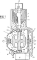
- FIG. 1 shows an embodiment of the gyroscopic system according to the invention, along a section plane passing through the axis of rotation of the router and through the axis of rotation of the secondary frame.
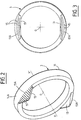
- Figure 2 is a schematic perspective view of the primary frame of the gyroscopic system according to the invention.
- Figure 3 is a front view of the primary frame of Figure 2.
- Figure 4 is a top view of a spherical portion of the primary frame of Figures 2 and 3, further illustrating the detection principle according to the invention.
- Figure 5 is a view similar to Figure 4 showing a variant of the arrangement of the marking lines according to the invention.
- the exemplary embodiment of the gyroscopic system according to the present invention comprises a housing 1 with a longitudinal axis L-L ′, inside which are a router 2, a primary frame 3 and a secondary frame 4.
- the router 2 the center of which is designated by O, is integral in rotation with a shaft 5, of axis ZZ 'intended to provide a vertical reference.
- the ends 5A and 5B of the shaft 5 are connected to the primary frame 3 by means of bearings, respectively 6 and 7.
- the spinning of the router 2 is caused, in this case, by a spiral leaf spring 8, housed in a housing 9 outside the housing 1 and intended to drive in rotation a shaft 10 integral, disengageable, of the shaft 5.
- a spiral leaf spring 8 housed in a housing 9 outside the housing 1 and intended to drive in rotation a shaft 10 integral, disengageable, of the shaft 5.
- the secondary frame 4 comprises first opposite hubs (not visible in FIG. 1), cooperating with bearings (also not visible) integral with the primary frame 3.
- the primary frame 3 can pivot, relative to the secondary frame 4, around of an axis YY 'meeting the axis ZZ' at the center O.
- the axis YY ' is perpendicular to the axis Z-Z'.
- the secondary frame 4 comprises opposite second hubs 4A and 4B, cooperating respectively with bearings 11 and 12 connected to the housing 1.
- the second hubs 4A and 4B and the bearings 11 and 12 define, for the secondary frame 4, a axis of rotation XX 'relative to the housing 1.
- the axis XX' passes through the center O and it is perpendicular to each of the axes ZZ 'and Y-Y'.
- marking means which are representative of the inclination of the plane defined by the axes of rotation YY 'and XX' of the primary 3 and secondary 4 frames relative to the axis of rotation ZZ 'of the router 2. According to the invention, these marking means are carried on the outer surface 13A of two spherical portions 13 of the primary frame 3, centered on the center O.
- each spherical portion 13 of the primary frame 3 has a generally triangular shape and projects from the annular ring 14, constituting the primary frame proper, in the extension of its external peripheral surface 14A.
- the two spherical portions 13 are provided on the ring 14, being arranged angularly spaced 180 ° and facing each other.
- said marking means are formed, on each spherical portion 13, by a set of parallel lines 15 of different lengths, extending from the base of the "triangle" constituted by the spherical portion 13 to the sides opposite to this base.
- the lines 15 extend at least substantially perpendicular to the plane defined by the axis of rotation ZZ 'of the router 2 and the axis of rotation YY' of the primary frame 3.
- the term "line” denotes a different reflectivity zone on the surface 13A and may be a slit, groove or etching with a blackened background (or a line in its usual sense) produced on said surface.
- the set of parallel lines 15 comprises at least one part in which the length of the lines 15 is successively increasing and at least one part in which the length of the lines 15 is successively decreasing.
- the set of lines 15 is arranged so that the one (or those, as in FIG. 4) of said lines which is the longest makes it possible to determine a reference position when the plane defined by the axes of rotation YY ' and XX ′ of the primary 3 and secondary 4 frames is perpendicular to the axis of rotation ZZ ′ of the router 2.
- said lines 15 are advantageously equidistant and the increase and decrease in length of a line relative to the previous are constant.
- the number of lines 15 can be any according to the desired resolution (the number of lines, twenty, shown in the figures should be considered as an indication only).
- FIG. 5 shows a variant of the arrangement of the marking lines 15, arranged in this case in a "staggered” fashion, relative to the ends 15A of said lines opening onto the sides of the "triangle" 13 opposite the base, and not symmetrically relative to the axis XX ′, as in FIG. 4.
- This arrangement makes it possible to obtain a larger pitch p of the lines to facilitate manufacture and optimize the resolution r .
- detection means 16 of the marking means 15 are provided, as well as processing means 17 (FIG. 4) of the information provided by the detection means 16. More specifically, the detection means 16, mounted on the housing 1 in front of a window thereof and facing the spherical portions 13 of the primary frame 3, as seen in FIG. 1, include lighting means 18, provided to form a light spot on the surface spherical 13A, and photosensitive means 19, provided for observing the light spot formed by the lighting means.
- the operating means 17 comprise counting means, associated with the photosensitive means 19, for counting the number of lines of said assembly observed by the photosensitive means during the rotation of the housing 1 relative to the primary frame 3, linked to the missile autorotation.
- the housing 1 is fixed, by its face 20 and by means of centering pins 21, on a missile (not shown), so that the axis LL 'of the housing is coincident with the roll axis RR 'of the missile.
- the operating means 17 will provide, at the output, the inclination of the yaw axis of the missile relative to the axis Z-Z 'of the router. Indeed, this yaw axis is then perpendicular to the plane X-X ', Y-Y'.
- the gyroscopic system of the invention could be applied to the monitoring of the pitch axis.
- a detection wheel 22 can be provided, opposite a detector 23, secured to the secondary frame 4 and coaxial with the axis XX ′.
- an electrical pulse is sent to the pyrotechnic igniter of the gyroscope. This impulse triggers the device for speeding up the router and unlocking the frames.
- the gyroscopic system is then operational (40 ms after firing).
- the roll and yaw (or pitch) detectors deliver the information obtained, in the latter case by reflection on the zones of different reflectivities.
- yaw detection makes it possible to measure the attitude in direction by delivering electrical signals generated by a code (set of lines) engraved directly on the primary frame.
Landscapes
- Physics & Mathematics (AREA)
- Engineering & Computer Science (AREA)
- General Physics & Mathematics (AREA)
- Radar, Positioning & Navigation (AREA)
- Remote Sensing (AREA)
- Control Of Position, Course, Altitude, Or Attitude Of Moving Bodies (AREA)
- Aiming, Guidance, Guns With A Light Source, Armor, Camouflage, And Targets (AREA)
- Gyroscopes (AREA)
Applications Claiming Priority (2)
| Application Number | Priority Date | Filing Date | Title |
|---|---|---|---|
| FR9411890A FR2725514B1 (fr) | 1994-10-05 | 1994-10-05 | Systeme gyroscopique pour missile en autorotation |
| FR9411890 | 1994-10-05 |
Publications (2)
| Publication Number | Publication Date |
|---|---|
| EP0706029A1 true EP0706029A1 (de) | 1996-04-10 |
| EP0706029B1 EP0706029B1 (de) | 1999-12-15 |
Family
ID=9467582
Family Applications (1)
| Application Number | Title | Priority Date | Filing Date |
|---|---|---|---|
| EP19950402186 Expired - Lifetime EP0706029B1 (de) | 1994-10-05 | 1995-09-29 | Kreiselsystem für Drallgeschoss |
Country Status (4)
| Country | Link |
|---|---|
| EP (1) | EP0706029B1 (de) |
| DE (1) | DE69513928T2 (de) |
| ES (1) | ES2140638T3 (de) |
| FR (1) | FR2725514B1 (de) |
Cited By (2)
| Publication number | Priority date | Publication date | Assignee | Title |
|---|---|---|---|---|
| RU2282135C1 (ru) * | 2005-02-10 | 2006-08-20 | Государственное унитарное предприятие "Конструкторское бюро приборостроения" | Блок управления управляемого вращающегося снаряда |
| CN109931824A (zh) * | 2017-12-15 | 2019-06-25 | 西安艾索信息技术有限公司 | 一种高精度、模块化导引头位标器 |
Families Citing this family (2)
| Publication number | Priority date | Publication date | Assignee | Title |
|---|---|---|---|---|
| RU2183817C1 (ru) * | 2000-10-23 | 2002-06-20 | Государственное унитарное предприятие "Конструкторское бюро приборостроения" | Управляемый снаряд |
| RU2231745C2 (ru) * | 2002-09-09 | 2004-06-27 | Государственное унитарное предприятие "Конструкторское бюро приборостроения" | Управляемый вращающийся снаряд |
Citations (5)
| Publication number | Priority date | Publication date | Assignee | Title |
|---|---|---|---|---|
| EP0068914A1 (de) * | 1981-05-18 | 1983-01-05 | Societe Anonyme De Telecommunications (S.A.T.) | Vorrichtung zur Koordinatenmessung einer rotierenden Erdkugel und Verfahren zur Erzeugung eines Teils der Vorrichtung |
| EP0485264A1 (de) | 1990-11-07 | 1992-05-13 | AEROSPATIALE Société Nationale Industrielle | Kreiselsystem zum Vermessen der Neigung der Ebene der Achsen des Primaeren und des sekundären Rahmens in Bezug auf die Kreiselackse |
| EP0489613A1 (de) | 1990-12-06 | 1992-06-10 | AEROSPATIALE Société Nationale Industrielle | Federangetriebener Kreisel mit Abkuppelungsmechanismus |
| US5138154A (en) * | 1990-04-04 | 1992-08-11 | Gyration Inc. | Shaft angle encoder with rotating off-axis interference pattern |
| EP0521757A1 (de) * | 1991-07-05 | 1993-01-07 | AEROSPATIALE Société Nationale Industrielle | Kreiselsystem zum Vermessen der Kreisellage |
-
1994
- 1994-10-05 FR FR9411890A patent/FR2725514B1/fr not_active Expired - Fee Related
-
1995
- 1995-09-29 EP EP19950402186 patent/EP0706029B1/de not_active Expired - Lifetime
- 1995-09-29 DE DE1995613928 patent/DE69513928T2/de not_active Expired - Fee Related
- 1995-09-29 ES ES95402186T patent/ES2140638T3/es not_active Expired - Lifetime
Patent Citations (5)
| Publication number | Priority date | Publication date | Assignee | Title |
|---|---|---|---|---|
| EP0068914A1 (de) * | 1981-05-18 | 1983-01-05 | Societe Anonyme De Telecommunications (S.A.T.) | Vorrichtung zur Koordinatenmessung einer rotierenden Erdkugel und Verfahren zur Erzeugung eines Teils der Vorrichtung |
| US5138154A (en) * | 1990-04-04 | 1992-08-11 | Gyration Inc. | Shaft angle encoder with rotating off-axis interference pattern |
| EP0485264A1 (de) | 1990-11-07 | 1992-05-13 | AEROSPATIALE Société Nationale Industrielle | Kreiselsystem zum Vermessen der Neigung der Ebene der Achsen des Primaeren und des sekundären Rahmens in Bezug auf die Kreiselackse |
| EP0489613A1 (de) | 1990-12-06 | 1992-06-10 | AEROSPATIALE Société Nationale Industrielle | Federangetriebener Kreisel mit Abkuppelungsmechanismus |
| EP0521757A1 (de) * | 1991-07-05 | 1993-01-07 | AEROSPATIALE Société Nationale Industrielle | Kreiselsystem zum Vermessen der Kreisellage |
Cited By (2)
| Publication number | Priority date | Publication date | Assignee | Title |
|---|---|---|---|---|
| RU2282135C1 (ru) * | 2005-02-10 | 2006-08-20 | Государственное унитарное предприятие "Конструкторское бюро приборостроения" | Блок управления управляемого вращающегося снаряда |
| CN109931824A (zh) * | 2017-12-15 | 2019-06-25 | 西安艾索信息技术有限公司 | 一种高精度、模块化导引头位标器 |
Also Published As
| Publication number | Publication date |
|---|---|
| FR2725514B1 (fr) | 1996-12-20 |
| ES2140638T3 (es) | 2000-03-01 |
| FR2725514A1 (fr) | 1996-04-12 |
| DE69513928D1 (de) | 2000-01-20 |
| EP0706029B1 (de) | 1999-12-15 |
| DE69513928T2 (de) | 2000-05-18 |
Similar Documents
| Publication | Publication Date | Title |
|---|---|---|
| WO1983004302A1 (fr) | Dispositf de manipulation d'une piece cylindrique ou spherique | |
| EP0647829B1 (de) | Verfahren und Vorrichtung zur geometrischen Kontrolle eines Fahrzeugs | |
| FR2542122A1 (fr) | Dispositif de support et d'orientation d'un element optique pour instrument analytique | |
| FR2858680A1 (fr) | Systeme de plate-forme stabilisee | |
| EP0706029B1 (de) | Kreiselsystem für Drallgeschoss | |
| FR2459154A1 (fr) | Dispositif a inertie pour corriger exactement l'orientation d'un projecteur de vehicule automobile en compensant l'effet des deplacements dynamiques de la partie suspendue par rapport a la partie non suspendue du vehicule. | |
| EP0033258B1 (de) | Windkraftmaschine mit einstellbarer Orientierung der Radwelle | |
| EP1045588A1 (de) | Vorrichtung zur Übertragung von digitalen Videobildern | |
| EP0521757B1 (de) | Kreiselsystem zum Vermessen der Kreisellage | |
| EP0740123A1 (de) | System zur Bestimmung der Lage und des Rollwinkels eines sich bewegenden Objektes | |
| EP0321342B1 (de) | Stabilisierendes Trägheitssystem für den Neigungswinkel von orientierbaren Bauteilen und mit diesem System verbundener Teleskopspiegel | |
| EP0485264B1 (de) | Kreiselsystem zum Vermessen der Neigung der Ebene der Achsen des Primaeren und des sekundären Rahmens in Bezug auf die Kreiselackse | |
| FR2615632A1 (fr) | Systeme d'analyse optico-mecanique n'utilisant qu'un seul polygone tournant | |
| EP0119123B1 (de) | Auswuchtvorrichtung, insbesondere für Kraftfahrzeugräder | |
| EP0176397A1 (de) | Vorrichtung zum Orientieren eines optischen Elementes | |
| EP0717264A1 (de) | Verfahren und Vorrichtung zum Schätzen von gyrometrischen Nullpunktabweichungen | |
| FR2610421A1 (fr) | Dispositif de deflexion de faisceau et imprimante a faisceau laser l'utilisant | |
| EP0239458B1 (de) | Kupplungsvorrichtung zweier paralleler Wellen zur mechanischen Übertragung einer Drehbewegung im Verhältnis 2/1 | |
| EP0969266A1 (de) | Vorrichtung mit mindestens zwei koaxialen Rädern und mit Mitteln zur Detektion derer Drehwinkellage | |
| EP0189721A1 (de) | Verfahren und Vorrichtung zur Messung des Einschlagwinkels eines Kraftfahrzeugvorderrades | |
| EP0158557A1 (de) | Vorrichtung zur Unterdrückung von Vibrationsgeräuschen in einem Laserkreisel und Anwendung dieser Vorrichtung | |
| CH626991A5 (en) | Rotary transducer for position measurement | |
| FR2847503A1 (fr) | Dispositif de positionnement angulaire a monter sur un outil portatif de percage | |
| EP0319396B1 (de) | Leuchtende Quelle für einen optischen Detektor und optische Messeinrichtung zur Verwendung dieser Quelle | |
| EP0161951B1 (de) | Kreiselsystem zur Detektion von Flugbahnabweichungen eines sich mindestens ungefähr geradlinig bewegenden Objektes |
Legal Events
| Date | Code | Title | Description |
|---|---|---|---|
| PUAI | Public reference made under article 153(3) epc to a published international application that has entered the european phase |
Free format text: ORIGINAL CODE: 0009012 |
|
| AK | Designated contracting states |
Kind code of ref document: A1 Designated state(s): BE CH DE ES GB GR IT LI NL PT SE |
|
| 17P | Request for examination filed |
Effective date: 19960422 |
|
| 17Q | First examination report despatched |
Effective date: 19980706 |
|
| GRAG | Despatch of communication of intention to grant |
Free format text: ORIGINAL CODE: EPIDOS AGRA |
|
| GRAG | Despatch of communication of intention to grant |
Free format text: ORIGINAL CODE: EPIDOS AGRA |
|
| GRAH | Despatch of communication of intention to grant a patent |
Free format text: ORIGINAL CODE: EPIDOS IGRA |
|
| GRAH | Despatch of communication of intention to grant a patent |
Free format text: ORIGINAL CODE: EPIDOS IGRA |
|
| GRAA | (expected) grant |
Free format text: ORIGINAL CODE: 0009210 |
|
| AK | Designated contracting states |
Kind code of ref document: B1 Designated state(s): BE CH DE ES GB GR IT LI NL PT SE |
|
| PG25 | Lapsed in a contracting state [announced via postgrant information from national office to epo] |
Ref country code: GR Free format text: LAPSE BECAUSE OF NON-PAYMENT OF DUE FEES Effective date: 19991215 |
|
| REG | Reference to a national code |
Ref country code: CH Ref legal event code: EP |
|
| RAP2 | Party data changed (patent owner data changed or rights of a patent transferred) |
Owner name: AEROSPATIALE MATRA |
|
| REG | Reference to a national code |
Ref country code: CH Ref legal event code: PFA Free format text: AEROSPATIALE SOCIETE NATIONALE INDUSTRIELLE TRANSFER- AEROSPATIALE MATRA Ref country code: CH Ref legal event code: NV Representative=s name: JOHN P. MUNZINGER INGENIEUR-CONSEIL |
|
| REF | Corresponds to: |
Ref document number: 69513928 Country of ref document: DE Date of ref document: 20000120 |
|
| GBT | Gb: translation of ep patent filed (gb section 77(6)(a)/1977) |
Effective date: 20000114 |
|
| NLT2 | Nl: modifications (of names), taken from the european patent patent bulletin |
Owner name: AEROSPATIALE MATRA |
|
| REG | Reference to a national code |
Ref country code: ES Ref legal event code: FG2A Ref document number: 2140638 Country of ref document: ES Kind code of ref document: T3 |
|
| ITF | It: translation for a ep patent filed | ||
| PG25 | Lapsed in a contracting state [announced via postgrant information from national office to epo] |
Ref country code: PT Free format text: LAPSE BECAUSE OF FAILURE TO SUBMIT A TRANSLATION OF THE DESCRIPTION OR TO PAY THE FEE WITHIN THE PRESCRIBED TIME-LIMIT Effective date: 20000315 |
|
| PLBE | No opposition filed within time limit |
Free format text: ORIGINAL CODE: 0009261 |
|
| STAA | Information on the status of an ep patent application or granted ep patent |
Free format text: STATUS: NO OPPOSITION FILED WITHIN TIME LIMIT |
|
| 26N | No opposition filed | ||
| REG | Reference to a national code |
Ref country code: GB Ref legal event code: IF02 |
|
| REG | Reference to a national code |
Ref country code: CH Ref legal event code: PCAR Free format text: JOHN P. MUNZINGER C/O CRONIN INTELLECTUAL PROPERTY;CHEMIN DE PRECOSSY 31;1260 NYON (CH) |
|
| PGFP | Annual fee paid to national office [announced via postgrant information from national office to epo] |
Ref country code: DE Payment date: 20070830 Year of fee payment: 13 |
|
| PGFP | Annual fee paid to national office [announced via postgrant information from national office to epo] |
Ref country code: ES Payment date: 20070913 Year of fee payment: 13 |
|
| PGFP | Annual fee paid to national office [announced via postgrant information from national office to epo] |
Ref country code: CH Payment date: 20070806 Year of fee payment: 13 |
|
| PGFP | Annual fee paid to national office [announced via postgrant information from national office to epo] |
Ref country code: GB Payment date: 20070926 Year of fee payment: 13 |
|
| PGFP | Annual fee paid to national office [announced via postgrant information from national office to epo] |
Ref country code: SE Payment date: 20070911 Year of fee payment: 13 Ref country code: NL Payment date: 20070919 Year of fee payment: 13 Ref country code: IT Payment date: 20070927 Year of fee payment: 13 Ref country code: BE Payment date: 20070821 Year of fee payment: 13 |
|
| BERE | Be: lapsed |
Owner name: *AEROSPATIALE MATRA Effective date: 20080930 |
|
| REG | Reference to a national code |
Ref country code: CH Ref legal event code: PL |
|
| GBPC | Gb: european patent ceased through non-payment of renewal fee |
Effective date: 20080929 |
|
| PG25 | Lapsed in a contracting state [announced via postgrant information from national office to epo] |
Ref country code: NL Free format text: LAPSE BECAUSE OF NON-PAYMENT OF DUE FEES Effective date: 20090401 |
|
| NLV4 | Nl: lapsed or anulled due to non-payment of the annual fee |
Effective date: 20090401 |
|
| PG25 | Lapsed in a contracting state [announced via postgrant information from national office to epo] |
Ref country code: BE Free format text: LAPSE BECAUSE OF NON-PAYMENT OF DUE FEES Effective date: 20080930 |
|
| PG25 | Lapsed in a contracting state [announced via postgrant information from national office to epo] |
Ref country code: IT Free format text: LAPSE BECAUSE OF NON-PAYMENT OF DUE FEES Effective date: 20080929 Ref country code: DE Free format text: LAPSE BECAUSE OF NON-PAYMENT OF DUE FEES Effective date: 20090401 |
|
| PG25 | Lapsed in a contracting state [announced via postgrant information from national office to epo] |
Ref country code: LI Free format text: LAPSE BECAUSE OF NON-PAYMENT OF DUE FEES Effective date: 20080930 Ref country code: CH Free format text: LAPSE BECAUSE OF NON-PAYMENT OF DUE FEES Effective date: 20080930 |
|
| REG | Reference to a national code |
Ref country code: ES Ref legal event code: FD2A Effective date: 20080930 |
|
| PG25 | Lapsed in a contracting state [announced via postgrant information from national office to epo] |
Ref country code: GB Free format text: LAPSE BECAUSE OF NON-PAYMENT OF DUE FEES Effective date: 20080929 |
|
| PG25 | Lapsed in a contracting state [announced via postgrant information from national office to epo] |
Ref country code: ES Free format text: LAPSE BECAUSE OF NON-PAYMENT OF DUE FEES Effective date: 20080930 |
|
| PG25 | Lapsed in a contracting state [announced via postgrant information from national office to epo] |
Ref country code: SE Free format text: LAPSE BECAUSE OF NON-PAYMENT OF DUE FEES Effective date: 20080930 |