EP0706093A1 - Méthode et dispositif d'alignement de masque et de pièce de travail - Google Patents
Méthode et dispositif d'alignement de masque et de pièce de travail Download PDFInfo
- Publication number
- EP0706093A1 EP0706093A1 EP95115797A EP95115797A EP0706093A1 EP 0706093 A1 EP0706093 A1 EP 0706093A1 EP 95115797 A EP95115797 A EP 95115797A EP 95115797 A EP95115797 A EP 95115797A EP 0706093 A1 EP0706093 A1 EP 0706093A1
- Authority
- EP
- European Patent Office
- Prior art keywords
- mask
- workpiece
- alignment
- projection lens
- light
- Prior art date
- Legal status (The legal status is an assumption and is not a legal conclusion. Google has not performed a legal analysis and makes no representation as to the accuracy of the status listed.)
- Granted
Links
- 238000000034 method Methods 0.000 title claims description 19
- 230000003287 optical effect Effects 0.000 claims abstract description 66
- 230000008569 process Effects 0.000 claims description 18
- 230000008859 change Effects 0.000 abstract description 5
- 230000000694 effects Effects 0.000 description 5
- 230000015572 biosynthetic process Effects 0.000 description 4
- 239000000428 dust Substances 0.000 description 4
- 239000004065 semiconductor Substances 0.000 description 3
- 230000009471 action Effects 0.000 description 2
- 230000004075 alteration Effects 0.000 description 2
- 230000008901 benefit Effects 0.000 description 2
- 230000008878 coupling Effects 0.000 description 2
- 238000010168 coupling process Methods 0.000 description 2
- 238000005859 coupling reaction Methods 0.000 description 2
- 238000003384 imaging method Methods 0.000 description 2
- 239000004973 liquid crystal related substance Substances 0.000 description 2
- 239000013307 optical fiber Substances 0.000 description 2
- 229920002120 photoresistant polymer Polymers 0.000 description 2
- 239000000758 substrate Substances 0.000 description 2
- 230000007423 decrease Effects 0.000 description 1
- 238000010586 diagram Methods 0.000 description 1
- 230000035945 sensitivity Effects 0.000 description 1
- 239000013598 vector Substances 0.000 description 1
Images






Classifications
-
- G—PHYSICS
- G03—PHOTOGRAPHY; CINEMATOGRAPHY; ANALOGOUS TECHNIQUES USING WAVES OTHER THAN OPTICAL WAVES; ELECTROGRAPHY; HOLOGRAPHY
- G03F—PHOTOMECHANICAL PRODUCTION OF TEXTURED OR PATTERNED SURFACES, e.g. FOR PRINTING, FOR PROCESSING OF SEMICONDUCTOR DEVICES; MATERIALS THEREFOR; ORIGINALS THEREFOR; APPARATUS SPECIALLY ADAPTED THEREFOR
- G03F7/00—Photomechanical, e.g. photolithographic, production of textured or patterned surfaces, e.g. printing surfaces; Materials therefor, e.g. comprising photoresists; Apparatus specially adapted therefor
- G03F7/20—Exposure; Apparatus therefor
-
- G—PHYSICS
- G03—PHOTOGRAPHY; CINEMATOGRAPHY; ANALOGOUS TECHNIQUES USING WAVES OTHER THAN OPTICAL WAVES; ELECTROGRAPHY; HOLOGRAPHY
- G03F—PHOTOMECHANICAL PRODUCTION OF TEXTURED OR PATTERNED SURFACES, e.g. FOR PRINTING, FOR PROCESSING OF SEMICONDUCTOR DEVICES; MATERIALS THEREFOR; ORIGINALS THEREFOR; APPARATUS SPECIALLY ADAPTED THEREFOR
- G03F9/00—Registration or positioning of originals, masks, frames, photographic sheets or textured or patterned surfaces, e.g. automatically
- G03F9/70—Registration or positioning of originals, masks, frames, photographic sheets or textured or patterned surfaces, e.g. automatically for microlithography
- G03F9/7003—Alignment type or strategy, e.g. leveling, global alignment
- G03F9/7023—Aligning or positioning in direction perpendicular to substrate surface
- G03F9/7026—Focusing
-
- G—PHYSICS
- G03—PHOTOGRAPHY; CINEMATOGRAPHY; ANALOGOUS TECHNIQUES USING WAVES OTHER THAN OPTICAL WAVES; ELECTROGRAPHY; HOLOGRAPHY
- G03F—PHOTOMECHANICAL PRODUCTION OF TEXTURED OR PATTERNED SURFACES, e.g. FOR PRINTING, FOR PROCESSING OF SEMICONDUCTOR DEVICES; MATERIALS THEREFOR; ORIGINALS THEREFOR; APPARATUS SPECIALLY ADAPTED THEREFOR
- G03F7/00—Photomechanical, e.g. photolithographic, production of textured or patterned surfaces, e.g. printing surfaces; Materials therefor, e.g. comprising photoresists; Apparatus specially adapted therefor
- G03F7/70—Microphotolithographic exposure; Apparatus therefor
- G03F7/70216—Mask projection systems
- G03F7/70241—Optical aspects of refractive lens systems, i.e. comprising only refractive elements
-
- G—PHYSICS
- G03—PHOTOGRAPHY; CINEMATOGRAPHY; ANALOGOUS TECHNIQUES USING WAVES OTHER THAN OPTICAL WAVES; ELECTROGRAPHY; HOLOGRAPHY
- G03F—PHOTOMECHANICAL PRODUCTION OF TEXTURED OR PATTERNED SURFACES, e.g. FOR PRINTING, FOR PROCESSING OF SEMICONDUCTOR DEVICES; MATERIALS THEREFOR; ORIGINALS THEREFOR; APPARATUS SPECIALLY ADAPTED THEREFOR
- G03F9/00—Registration or positioning of originals, masks, frames, photographic sheets or textured or patterned surfaces, e.g. automatically
-
- H—ELECTRICITY
- H05—ELECTRIC TECHNIQUES NOT OTHERWISE PROVIDED FOR
- H05K—PRINTED CIRCUITS; CASINGS OR CONSTRUCTIONAL DETAILS OF ELECTRIC APPARATUS; MANUFACTURE OF ASSEMBLAGES OF ELECTRICAL COMPONENTS
- H05K3/00—Apparatus or processes for manufacturing printed circuits
- H05K3/0073—Masks not provided for in groups H05K3/02 - H05K3/46, e.g. for photomechanical production of patterned surfaces
- H05K3/0082—Masks not provided for in groups H05K3/02 - H05K3/46, e.g. for photomechanical production of patterned surfaces characterised by the exposure method of radiation-sensitive masks
Definitions
- the invention relates to process for positioning a mask relative to a workpiece, and to a device for executing the process in an exposure device which is used for the production of a semiconductor device, a printed board, and an LCD (liquid crystal display) and for similar purposes.
- exposure devices of the projection type are known in which positioning is done using exposure light, for example an i-line, an h-line or a g-line (i-line: 365 nm wavelength, h-line: 405 nm wavelength, g-line: 436 nm wavelength), or in which positioning is done using nonexposure light, for example, an e-line, a d-line or a c-line (e-line: 546 nm wavelength, d-line: 588 nm wavelength, c-line: 656 nm wavelength).
- exposure light for example an i-line, an h-line or a g-line (i-line: 365 nm wavelength, h-line: 405 nm wavelength, g-line: 436 nm wavelength)
- nonexposure light for example, an e-line, a d-line or a c-line (e-line: 546 nm wavelength, d-line: 588 nm wavelength
- the region of the circuit pattern is not limited by the positioning region since the photoresist is not exposed to the action of exposure light during positioning.
- Figure 10 shows a schematic of an arrangement of the conventional exposure device in which positioning is done using the above described e-line.
- reference number 1 labels an emission device of exposure light
- reference number 1a labels a shutter
- reference number 1b an optical filter
- reference number 1c a condenser lens.
- Reference number 2 is a mask drive carrier on which by means of a suction device (vacuum chuck) or the like a mask M is secured, and which is driven by means of a drive device (not shown) in the x-y-z- ⁇ directions (x-axis, y-axis: orthogonal axes on a plane parallel to the mask surface, z-axis: an axis in the direction up and down in the drawing, ⁇ -axis: an axis of rotation around the z-axis). Furthermore, a mask pattern and mask alignment identifiers MA which are hereafter called a "mask identifier" are recorded on mask M for purposes of positioning.
- a mask pattern and mask alignment identifiers MA which are hereafter called a "mask identifier" are recorded on mask M for purposes of positioning.
- Reference number 3 indicates a projection lens and reference letter W labels a workpiece on which workpiece alignment identifiers WA, which are hereafter called the "workpiece identifiers", is recorded for purposes of positioning.
- Reference number 6 labels an alignment unit which consists of lens 6a, objective lens 6b, half mirror 6c and an image converter 6d provided with a CCD camera.
- Workpiece identifiers WA and mask identifiers MA projected onto workpiece W are detected via half mirror 6c ⁇ objective lens 6b ⁇ lens 6a by means of image converter 6d, and the positions of the two identifiers are observed.
- the alignment unit can, furthermore, also be located in region A or C in the drawing in addition to region B in the drawing.
- the e-line is emitted first from the emission device of exposure light 1 as nonexposure light, by means of alignment unit 6, workpiece identifiers WA and mask identifiers MA projected onto workpiece W are orbserved and the mask M or the workpiece W is moved in the x-y direction such that the two agree with one another. After completed positioning, the i-line is then emitted as exposure light from the exposure light emission device 1, the mask pattern is projected onto workpiece W and exposure is performed.
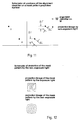
- the position of the projection image of the mask identifiers MA' on mask pattern projection surface E is changed by the position of the alignment identifier. This means that different values for distances ⁇ L and ⁇ L' between the workpiece identifiers and the projected mask identifiers are obtained, as is shown in Fig. 11.
- the mask pattern formed by the nonexposure light is distorted, as is shown in Fig. 12.
- the deviation of the projection surface was corrected by the fact that a parallel flat plate was inserted in the optical path of the projection optices system, and according to the wavelengths of the nonexposure light, the thickness of the flat plate was changed or the inclination thereof adjusted (Japanese patent HEI 5-43168).
- the deviation of the projection image by the exposure light and the nonexposure light is corrected by inserting the parallel flat plate between the projection lens and the workpiece, the property being used that by inserting the parallel flat plate in the optical path, the focal position deviates by S, as is shown in Fig. 13.
- the parallel flat plate has the property that it has no effect on the imaging characteristic of the optical system, even if it is moved in the direction of the optical axis and in the direction perpendicular to the optical axis. Also, the advantage arises that it is not necessary to push in the parallel flat plate with high positioning accuracy, so that prompt switchover can be achieved.
- the amount of focal correction by the parallel flat plate is labelled ⁇ S
- the thickness of the parallel flat plate is labelled d and the index of refraction is labelled N
- Fig. 14 illustrates the focal position as a function of wavelength.
- the errors also change if the combination of wavelengths changes.
- ⁇ S1 an amount of focal correction ⁇ S1 is obtained in the case in which the wavelength for exposure is 405 nm and the wavelength for alignment is 546 nm
- an amount of focal correction of ⁇ S2 is obtained if the wavelength for exposure is 436 nm and the wavelength for alignment is 578 nm.
- the thickness of the parallel flat plate must be changed according to the combination of wavelength for exposure and wavelength for alignment.
- the combination of the wavelengths is changed for exposure depending on the resist to be used and the substrate of the workpiece to be treated.
- the parallel flat plate When the parallel flat plate is used, as in the above described conventional example, therefore, it is considered disadvantageous that the parallel flat plates must be made available according to the number of the combinations of the wavelengths for exposure and wavelength for alignment and the parallel flat plates in conjunction with the combinations must be pushed in, and that therefore the pushing device is complicated.
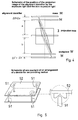
- Fig. 15 schematically shows a deviation of the optical path in the case in which the parallel flat plate is pushed in the optical path such that it is inclined relative to the optical axis.
- a position deviation of ⁇ Y occurs if the parallel flat plate with a thickness of d (mm) is inclined with reference to the optical axis by ⁇ (radiant).
- This position deviation ⁇ Y can be determined according to the following formula if the index of refraction of the parallel flat plate is designated N.
- ⁇ Y ((N - 1)/N) d ⁇ ⁇
- a primary object of the invention is to devise a process for positioning of a mask to a workpiece in which, in an exposure device in which alignment is performed using light with wavelengths which are different from that of the exposure light, positioning of the mask relative to the workpiece can be achieved with high accuracy by the magnification factor in emission of exposure light and the magnification factor for emission of nonexposure light being brought into agreement with one another.
- Another object consists in devising a device for executing the process.
- the length of the optical path of the optical system is adjusted such that the magnification factor in the emission of nonexposure light agrees with a magnification factor in emission of exposure light, that the nonexposure light is emitted onto a mask, that the alignment identifiers of the workpiece and the alignment identifiers of the mask are detected, and that the workpiece or the mask is moved parallel to a workpiece/mask surface, such that the alignment identifiers of the workpiece and the alignment identifiers of the mask come to lie one on top of the other.
- the optical component is inserted for purposes of focal length correction, and that the adjustment is accomplished such that the magnification factor in the emission of nonexposure light agrees with the magnification factor in the emission of exposure light.
- the above described objects are achieved according to the invention by the fact that in the device for positioning the mask relative to a workpiece which has an emission device for emission of ultraviolet rays onto a mask, a mask, a mask drive carrier for movement of the above described mask, a projection lens, a workpiece, a workpiece drive carrier for movement of the above described workpiece, an image recording means for image recording of alignment identifiers of the workpiece and alignment identifiers of the mask, and a control means for control of the movements of the mask drive carrier and the workpiece drive carrier, the control means takes into account changes of the focal length and the movements of the principal planes of the projection lens by wavelengths, that the length of the optical path of the optical system is adjusted such that the magnification factor in emission of nonexposure light agrees with the magnification factor in emission of exposure light, that the nonexposure light is emitted onto the mask, and that the workpiece drive carrier or the mask drive carrier is moved parallel to the workpiece/mask surface such that the alignment identifiers of the workpiece and
- the magnification factor in the emission of light with the exposure wavelengths and the magnification factor in the emission of light with the nonexposure wavelengths can, likewise, be made the same size if, instead of the above described movement of the two positions of the workpiece and the mask relative to the projection lens, only the workpiece or the mask is moved relative to the projection lens, and the optical part, such as the parallel flat plate or the like, is pushed between the mask or the workpiece which was not moved and the projection lens.
- magnification factor in the emission of light with the nonexposure wavelengths and the magnification factor in the emission of light with the exposure wavelengths are brought into agreement with one another and thus positioning of the mask to the workpiece is done.
- the measure by means of the measure by which at least two of the following parts, specifically the mask, the projection lens or the workpiece, are moved jointly and the distances to one another adjusted, alignment can be done with great precision by the nonexposure light using a simple device without using the parallel flat plate or the like. Furthermore, in doing so the occurence of position deviation as the result of the inclination of the flat plate is prevented. In addition, this measure can also be easily taken in the case of altered exposure light and altered alignment light.
- the workpiece is prevented from becoming fouled by the formation of dust when the parallel flat plate is pushed in and removed since it is not necessary to push the parallel flat plate in the optical path.
- the optical component is inserted between the mask and the projection lens and/or between the projection lens and the workpiece for purposes of focal correction and in which the distance is adjusted between the projection lens and the workpiece, or between the mask and the projection lens, where the above described optical component is not inserted, alignment by the nonexposure light can be performed without moving the workpiece drive carrier or the mask drive carrier in the direction of the optical axis, the effect of the position deviation on accuracy, when the carrier moves, can be eliminated, and thus, alignment can be achieved with high precision.
- Fig. 1 is a schematic of an arrangement of an exposure device according to a first embodiment of the invention in which a light emission device 1 has a shutter 1a to control the emission of exposure light and nonexposure light, an optical filter 1b and a condenser lens 1c.
- the light which is emitted from an ultraviolet lamp (not shown) is incident, via the shutter 1a and optical filter 1b, on condenser lens 1c, and is converted by means of the condenser lens 1c into parallel light which is then incident on a mask M.
- a mask drive carrier 2 has a means for attaching mask M, such as a suction device or the like, and the carrier 2 is driven by means of a drive device (not shown) in the x-y-z- ⁇ directions (x-axis, y-axis, two orthogonal axes on a plane parallel to the mask surface, z-axis: an axis in the direction up an down in the drawing, ⁇ -axis: an axis of rotation around an axis perpendicular to the mask carrier). Furthermore, a mask pattern and mask identifiers are recorded on mask M for purposes of positioning.
- a projection lens 3 has a projection lens drive carrier 4 for moving the projection lens in the z-direction. Furthermore, a workpiece W is positioned on a workpiece drive carrier 5 which has a means for attachment of the workpiece, as in mask drive carrier 2, and which is driven by a drive device (not shown) in the x-y-z- ⁇ directions. Additionally, workpiece identifiers are recorded on workpiece W for purposes of positioning.
- An alignment unit 6 is comprised of a lens 6a, an objective lens 6b, a half mirror 6c, image converter 6d, mirror 6e, optical fibers 6f, shutter 6g and lens 6h, as is shown in the drawing.
- the nonexposure light is emitted from a light source onto the mask identifier and the workpiece identifier via optical fibers 6f - shutter 6g - lens 6h - half mirror 6c - lens 6b - mirror 6e.
- Reflected light is detected via the mirror 6e - objective lens 6b - half mirror 6c - lens 6a by means of the image converter 6d, and thus, alignment is performed.
- the two alignment units 6 there are at least two alignment units 6.
- two alignment identifiers recorded on the workpiece/mask are observed, and in this way, positioning of mask M relative to the workpiece W is performed, as is described below.
- Alignment units 6 can, furthermore, be moved in the direction of the adjacent horizontal arrow shown in the drawing. Each alignment unit is pushed during alignment into the position shown in the figure and is pushed back (away from exposure device 1) during exposure. In the case in which the alignment unit is located outside the exposure area, it is not necessary to move the alignment unit out of the way.
- Fig. 2 is a schematic of an arrangement of a control device of the Fig. 1 embodiment of the invention.
- an arithmetic-logic unit 21, a control console 22, and a carrier control element 23 are shown.
- the carrier control element 23 controls an x-carrier, a y-carrier, a z-carrier and a ⁇ -carrier of mask drive carrier 2, projection lens drive carrier 4 and the workpiece drive carrier 5, shown in Fig. 1.
- reference symbols H and H' designate the principal planes of the projection lens for the light with exposure wavelengths.
- the focal length is computed by f + ⁇ f, and the following formula as is illustrated in Fig.
- the distance between the mask M and projection lens 3 is labelled a and the distance between projection lens 3 and workpiece W is labelled b
- the magnification factor for emission of light with the exposure wavelengths and the magnification factor for emission of light with the nonexposure wavelengths can be made the same size by the distance between mask M and projection lens 3 being designate a + ⁇ H and ⁇ a and the distance between projection lens 3 and workpiece W being designated.
- b + ⁇ H' + ⁇ b (b + ⁇ H' + m ⁇ a).
- magnification factors can be made the same size means that the mask identifier in the emission of light with the exposure wavelengths and in the emission of light with the nonexposure wavelengths is projected onto the same position on the workpiece, as is shown in the drawing.
- the mask identifier can be projected onto the same position as during exposure and alignment can be performed without making a focal correction by means of the optical path, such as the parallel flat plate or the like.
- the workpiece is prevented from becoming fouled by the formation of dust when the parallel flat plate is inserted and removed, since it is not necessary to push the parallel flat plate in the optical path.
- focal correction with respect to the nonexposure light is accomplished by the mask drive carrier and the workpiece drive carrier being moved in the direction of the optical axis of the projection lens.
- the focal length correction can, likewise, be achieved in the manner described below, the relative distances between the projection lens, the mask and the workpiece being changed.
- the alignment units are located above the mask.
- the alignment units can also be located between the projection lens and the workpiece, the nonexposure light can be emitted from the emission device for the exposure light, and alignment can be accomplished.
- Fig. 7 schematically shows the arrangement of an exposure device according to a second embodiment of the invention.
- the same parts as in Fig. 1 are provided with the same reference numbers as in Fig. 1.
- the focal correction with respect to the nonexposure light is performed by changing the distance between mask M and the projection lens and at the same time by pushing parallel flat plates 11, 11' between projection lens 3 and workpiece W.
- the focal position can be shifted as shown in Fig. 13; this corresponds to a change of the distance between projection lens 3 and workpiece W.
- parallel flat plates are made available beforehand with a thickness in which a focal length correction can be obtained which corresponds to the amount of correction of the above described distance between the projection lens and the workpiece.
- the distance is changed between mask M and the projection lens and at the same time parallel flat plates 11, 11' are inserted between projection lens 3 and workpiece W.
- the magnification factor in emission of exposure light and the magnification factor in emission of nonexposure light can be made the same.
- Exposure is performed in this embodiment in the following manner.
- the parallel flat plate is inserted between the projection lens and the workpiece, and thus, the magnification factors with respect to exposure light and nonexposure light are brought into agreement with one another, the problem of position deviation of the mask identifiers projected onto the workpiece can be prevented by the position of the alignment identifiers, and alignment can be obtained with high precision by nonexposure light using a simple device.
- the mask drive carrier is moved in the direction of the optical axis of the projection lens, and at the same time, the parallel flat plate 11 is inserted between the projection lens and the workpiece.
- the focal correction can, likewise, be performed by changing the distance between the projection lens and the workpiece, and at the same time, by pushing the parallel flat plates 11, 11' between the mask and the projection lens.
- the alignment units are located above the mask.
- the alignment units can also be located between the projection lens and the workpiece, the nonexposure light emitted from the emission device of the exposure light and alignment accomplished.
- two parallel flat plates 11, 11' are made provided and inserted from both sides of the optical path.
- one large parallel flat plate can also be provided and pushed into the optical path from one side of the optical path.
- Fig. 8 schematically shows the arrangement of an exposure device according to the third embodiment of the invention.
- the same parts as in Fig. 1 are provided with the same reference numbers as in Fig. 1.
- parallel flat plates 11 and 11' are pushed between mask M and the projection lens 3 and between projection lens 3 and workpiece W, and thus, the focal length correction is obtained with respect to the nonexposure light.
- parallel flat plates are made available beforehand of a thickness by which a focal correction can be performed which corresponds to the amount of correction ⁇ a of the distance between the mask M and the projection lens 3, and the amount of correction of the distance between the projection lens and the workpiece.
- the magnification factors with respect to exposure light and nonexposure light are brought into agreement with one another, occurrence of the problem of position deviation of the mask identifier projected onto the workpiece can be prevented by the position of the alignment identifiers, and alignments can be obtained with high precision by the nonexposure light using a simple device.
- the alignment units are located above the mask.
- the alignment units can also be located between the projection lens and the workpiece, the nonexposure light can be emitted from the emission device of the exposure light and thus alignment can be accomplished.
- two parallel flat plates are inserted in from both sides of the optical path.
- one large parallel flat plate can also be made available and inserted into the optical path from one side on the optical path.
Landscapes
- Physics & Mathematics (AREA)
- General Physics & Mathematics (AREA)
- Exposure And Positioning Against Photoresist Photosensitive Materials (AREA)
- Exposure Of Semiconductors, Excluding Electron Or Ion Beam Exposure (AREA)
Applications Claiming Priority (3)
| Application Number | Priority Date | Filing Date | Title |
|---|---|---|---|
| JP6242532A JP2994968B2 (ja) | 1994-10-06 | 1994-10-06 | マスクとワークの位置合わせ方法および装置 |
| JP242532/94 | 1994-10-06 | ||
| JP24253294 | 1994-10-06 |
Publications (2)
| Publication Number | Publication Date |
|---|---|
| EP0706093A1 true EP0706093A1 (fr) | 1996-04-10 |
| EP0706093B1 EP0706093B1 (fr) | 1999-08-04 |
Family
ID=17090518
Family Applications (1)
| Application Number | Title | Priority Date | Filing Date |
|---|---|---|---|
| EP95115797A Expired - Lifetime EP0706093B1 (fr) | 1994-10-06 | 1995-10-06 | Méthode et dispositif d'alignement de masque et de pièce de travail |
Country Status (6)
| Country | Link |
|---|---|
| US (1) | US5721079A (fr) |
| EP (1) | EP0706093B1 (fr) |
| JP (1) | JP2994968B2 (fr) |
| KR (1) | KR0185773B1 (fr) |
| DE (1) | DE69511201T2 (fr) |
| TW (1) | TW320735B (fr) |
Families Citing this family (10)
| Publication number | Priority date | Publication date | Assignee | Title |
|---|---|---|---|---|
| US6068949A (en) * | 1995-04-13 | 2000-05-30 | Rentech, Inc. | Alkali metal ion battery electrode material |
| JP2994232B2 (ja) * | 1995-07-28 | 1999-12-27 | ウシオ電機株式会社 | マスクとマスクまたはマスクとワークの位置合わせ方法および装置 |
| US5978066A (en) * | 1997-10-06 | 1999-11-02 | Agfa-Gevaert Ag | Method of copying transparent originals and photographic copier |
| JP3827645B2 (ja) * | 2003-02-19 | 2006-09-27 | 株式会社新川 | ボンディング装置及びボンディング外観検査装置 |
| US7589818B2 (en) * | 2003-12-23 | 2009-09-15 | Asml Netherlands B.V. | Lithographic apparatus, alignment apparatus, device manufacturing method, and a method of converting an apparatus |
| JP4641779B2 (ja) * | 2004-10-20 | 2011-03-02 | ウシオ電機株式会社 | 露光装置 |
| CN103034071B (zh) * | 2012-12-13 | 2014-11-19 | 京东方科技集团股份有限公司 | 一种曝光机对位方法及控制设备 |
| CN106813815B (zh) * | 2015-11-27 | 2019-03-01 | 苏州市亿利华电子有限公司 | 一种pcb板对位自动检测装置 |
| JP6717719B2 (ja) * | 2016-09-09 | 2020-07-01 | 株式会社Screenホールディングス | パターン露光装置、露光ヘッドおよびパターン露光方法 |
| CN112808549B (zh) * | 2021-02-02 | 2024-05-31 | 北京梦之墨科技有限公司 | 一种光处理设备 |
Citations (5)
| Publication number | Priority date | Publication date | Assignee | Title |
|---|---|---|---|---|
| JPS60223122A (ja) * | 1984-04-19 | 1985-11-07 | Canon Inc | 投影露光装置 |
| US4561773A (en) * | 1982-11-17 | 1985-12-31 | Canon Kabushiki Kaisha | Projection exposure apparatus |
| US4922290A (en) * | 1987-10-06 | 1990-05-01 | Hitachi, Ltd. | Semiconductor exposing system having apparatus for correcting change in wavelength of light source |
| US5159496A (en) * | 1990-04-04 | 1992-10-27 | Dainippon Screen Mfg. Co., Ltd. | Lens system with four meniscus lenses made of anomalous dispersion glass |
| JPH0543168A (ja) | 1991-08-07 | 1993-02-23 | Mitsubishi Electric Corp | リニアモータ駆動エレベーター |
Family Cites Families (2)
| Publication number | Priority date | Publication date | Assignee | Title |
|---|---|---|---|---|
| JP2799575B2 (ja) * | 1988-09-30 | 1998-09-17 | キヤノン株式会社 | 露光方法 |
| US5279911A (en) * | 1990-07-23 | 1994-01-18 | Mitsubishi Denki Kabushiki Kaisha | Photomask |
-
1994
- 1994-10-06 JP JP6242532A patent/JP2994968B2/ja not_active Expired - Fee Related
-
1995
- 1995-10-06 KR KR1019950034611A patent/KR0185773B1/ko not_active Expired - Fee Related
- 1995-10-06 US US08/540,390 patent/US5721079A/en not_active Expired - Lifetime
- 1995-10-06 DE DE69511201T patent/DE69511201T2/de not_active Expired - Lifetime
- 1995-10-06 EP EP95115797A patent/EP0706093B1/fr not_active Expired - Lifetime
- 1995-10-11 TW TW084110662A patent/TW320735B/zh not_active IP Right Cessation
Patent Citations (7)
| Publication number | Priority date | Publication date | Assignee | Title |
|---|---|---|---|---|
| US4561773A (en) * | 1982-11-17 | 1985-12-31 | Canon Kabushiki Kaisha | Projection exposure apparatus |
| JPS60223122A (ja) * | 1984-04-19 | 1985-11-07 | Canon Inc | 投影露光装置 |
| US4616130A (en) * | 1984-04-19 | 1986-10-07 | Canon Kabushiki Kaisha | Projection exposure apparatus |
| JPH0543168B2 (fr) * | 1984-04-19 | 1993-06-30 | Canon Kk | |
| US4922290A (en) * | 1987-10-06 | 1990-05-01 | Hitachi, Ltd. | Semiconductor exposing system having apparatus for correcting change in wavelength of light source |
| US5159496A (en) * | 1990-04-04 | 1992-10-27 | Dainippon Screen Mfg. Co., Ltd. | Lens system with four meniscus lenses made of anomalous dispersion glass |
| JPH0543168A (ja) | 1991-08-07 | 1993-02-23 | Mitsubishi Electric Corp | リニアモータ駆動エレベーター |
Also Published As
| Publication number | Publication date |
|---|---|
| JPH08107061A (ja) | 1996-04-23 |
| DE69511201D1 (de) | 1999-09-09 |
| TW320735B (fr) | 1997-11-21 |
| JP2994968B2 (ja) | 1999-12-27 |
| US5721079A (en) | 1998-02-24 |
| DE69511201T2 (de) | 1999-12-30 |
| KR960015073A (ko) | 1996-05-22 |
| EP0706093B1 (fr) | 1999-08-04 |
| KR0185773B1 (ko) | 1999-04-01 |
Similar Documents
| Publication | Publication Date | Title |
|---|---|---|
| EP0764885B1 (fr) | Procédé de positionnement d'un masque par rapport à une pièce à traiter et appareil d' exposition par projection de mise en oeuvre de ce procédé | |
| US5874190A (en) | Process for projection exposure of a workpiece with back alignment marks | |
| EP0756207B1 (fr) | Procédé de positionnement d'un masque par rapport à un autre masque et une pièce à traiter et dispositif de mise en oeuvre de ce procédé | |
| US4617469A (en) | Exposure apparatus with detecting means insertable into an exposure path | |
| EP0706093B1 (fr) | Méthode et dispositif d'alignement de masque et de pièce de travail | |
| US6124922A (en) | Exposure device and method for producing a mask for use in the device | |
| US5777747A (en) | Process for positioning a mask relative to a workpiece and device for performing the process | |
| US6268902B1 (en) | Exposure apparatus, and manufacturing method for devices using same | |
| US7050151B2 (en) | Exposure apparatus, exposure method, and device manufacturing method | |
| KR100308608B1 (ko) | 위치맞춤장치및투영노광장치 | |
| US6426508B1 (en) | Surface-position detection device, a projection exposure apparatus using the device, and a device manufacturing method using the apparatus | |
| CN121069715A (zh) | 一种离轴对准装置、离轴对准方法以及光刻设备 | |
| JP3441930B2 (ja) | 走査型露光装置およびデバイス製造方法 | |
| JP3152133B2 (ja) | マスクとワークの位置合わせ方法および装置 | |
| JP2006278799A (ja) | 位置計測方法及び該位置計測方法を使用したデバイス製造方法 | |
| JPH07297115A (ja) | マスクとワークの位置合わせ方法および装置 | |
| JPH08124836A (ja) | マスクとワークの位置合わせ方法および装置 | |
| JP2003035511A (ja) | 位置検出装置、および該位置検出装置を備えた露光装置 | |
| JPH0584664B2 (fr) | ||
| JPH09297408A (ja) | プリアライメント装置 | |
| JPH0723933B2 (ja) | 光路長補償光学系 | |
| JP2005197276A (ja) | 露光方法、露光装置及び該露光方法を用いた電子デバイスの製造方法 | |
| KR20020092024A (ko) | 순차정렬장치 및 방법 | |
| JP2001093812A (ja) | 半導体露光装置、位置合わせ装置およびデバイス製造方法 | |
| JP2006120777A (ja) | ウエハ撮像装置 |
Legal Events
| Date | Code | Title | Description |
|---|---|---|---|
| PUAI | Public reference made under article 153(3) epc to a published international application that has entered the european phase |
Free format text: ORIGINAL CODE: 0009012 |
|
| AK | Designated contracting states |
Kind code of ref document: A1 Designated state(s): DE FR GB IT NL |
|
| 17P | Request for examination filed |
Effective date: 19960326 |
|
| 17Q | First examination report despatched |
Effective date: 19971222 |
|
| GRAG | Despatch of communication of intention to grant |
Free format text: ORIGINAL CODE: EPIDOS AGRA |
|
| GRAG | Despatch of communication of intention to grant |
Free format text: ORIGINAL CODE: EPIDOS AGRA |
|
| GRAH | Despatch of communication of intention to grant a patent |
Free format text: ORIGINAL CODE: EPIDOS IGRA |
|
| GRAH | Despatch of communication of intention to grant a patent |
Free format text: ORIGINAL CODE: EPIDOS IGRA |
|
| GRAA | (expected) grant |
Free format text: ORIGINAL CODE: 0009210 |
|
| AK | Designated contracting states |
Kind code of ref document: B1 Designated state(s): DE FR GB IT NL |
|
| PG25 | Lapsed in a contracting state [announced via postgrant information from national office to epo] |
Ref country code: NL Free format text: LAPSE BECAUSE OF FAILURE TO SUBMIT A TRANSLATION OF THE DESCRIPTION OR TO PAY THE FEE WITHIN THE PRESCRIBED TIME-LIMIT Effective date: 19990804 Ref country code: IT Free format text: LAPSE BECAUSE OF FAILURE TO SUBMIT A TRANSLATION OF THE DESCRIPTION OR TO PAY THE FEE WITHIN THE PRE;WARNING: LAPSES OF ITALIAN PATENTS WITH EFFECTIVE DATE BEFORE 2007 MAY HAVE OCCURRED AT ANY TIME BEFORE 2007. THE CORRECT EFFECTIVE DATE MAY BE DIFFERENT FROM THE ONE RECORDED.SCRIBED TIME-LIMIT Effective date: 19990804 Ref country code: FR Free format text: LAPSE BECAUSE OF FAILURE TO SUBMIT A TRANSLATION OF THE DESCRIPTION OR TO PAY THE FEE WITHIN THE PRESCRIBED TIME-LIMIT Effective date: 19990804 |
|
| REF | Corresponds to: |
Ref document number: 69511201 Country of ref document: DE Date of ref document: 19990909 |
|
| EN | Fr: translation not filed | ||
| NLV1 | Nl: lapsed or annulled due to failure to fulfill the requirements of art. 29p and 29m of the patents act | ||
| PLBE | No opposition filed within time limit |
Free format text: ORIGINAL CODE: 0009261 |
|
| STAA | Information on the status of an ep patent application or granted ep patent |
Free format text: STATUS: NO OPPOSITION FILED WITHIN TIME LIMIT |
|
| 26N | No opposition filed | ||
| REG | Reference to a national code |
Ref country code: GB Ref legal event code: IF02 |
|
| PGFP | Annual fee paid to national office [announced via postgrant information from national office to epo] |
Ref country code: DE Payment date: 20121003 Year of fee payment: 18 |
|
| PGFP | Annual fee paid to national office [announced via postgrant information from national office to epo] |
Ref country code: GB Payment date: 20121003 Year of fee payment: 18 |
|
| GBPC | Gb: european patent ceased through non-payment of renewal fee |
Effective date: 20131006 |
|
| PG25 | Lapsed in a contracting state [announced via postgrant information from national office to epo] |
Ref country code: GB Free format text: LAPSE BECAUSE OF NON-PAYMENT OF DUE FEES Effective date: 20131006 |
|
| REG | Reference to a national code |
Ref country code: DE Ref legal event code: R119 Ref document number: 69511201 Country of ref document: DE Effective date: 20140501 |
|
| PG25 | Lapsed in a contracting state [announced via postgrant information from national office to epo] |
Ref country code: DE Free format text: LAPSE BECAUSE OF NON-PAYMENT OF DUE FEES Effective date: 20140501 |