EP0706249B1 - Verbesserungen an Geräteträger-Elementen für Kabelhalter - Google Patents
Verbesserungen an Geräteträger-Elementen für Kabelhalter Download PDFInfo
- Publication number
- EP0706249B1 EP0706249B1 EP95402190A EP95402190A EP0706249B1 EP 0706249 B1 EP0706249 B1 EP 0706249B1 EP 95402190 A EP95402190 A EP 95402190A EP 95402190 A EP95402190 A EP 95402190A EP 0706249 B1 EP0706249 B1 EP 0706249B1
- Authority
- EP
- European Patent Office
- Prior art keywords
- base
- support
- plate
- flanges
- channel
- Prior art date
- Legal status (The legal status is an assumption and is not a legal conclusion. Google has not performed a legal analysis and makes no representation as to the accuracy of the status listed.)
- Expired - Lifetime
Links
- 230000000717 retained effect Effects 0.000 abstract 1
- 210000005069 ears Anatomy 0.000 description 8
- 244000245420 ail Species 0.000 description 7
- 239000002184 metal Substances 0.000 description 7
- 229910052751 metal Inorganic materials 0.000 description 7
- 210000004027 cell Anatomy 0.000 description 6
- 239000000463 material Substances 0.000 description 3
- 240000008042 Zea mays Species 0.000 description 2
- 239000002131 composite material Substances 0.000 description 2
- 241001080024 Telles Species 0.000 description 1
- 238000004026 adhesive bonding Methods 0.000 description 1
- 230000000712 assembly Effects 0.000 description 1
- 238000000429 assembly Methods 0.000 description 1
- 230000000903 blocking effect Effects 0.000 description 1
- 230000001609 comparable effect Effects 0.000 description 1
- 238000006073 displacement reaction Methods 0.000 description 1
- 230000000694 effects Effects 0.000 description 1
- 238000009434 installation Methods 0.000 description 1
- 150000002739 metals Chemical class 0.000 description 1
- 230000000750 progressive effect Effects 0.000 description 1
- 230000002441 reversible effect Effects 0.000 description 1
- 238000000926 separation method Methods 0.000 description 1
- 239000007787 solid Substances 0.000 description 1
- 238000003466 welding Methods 0.000 description 1
Images

Classifications
-
- H—ELECTRICITY
- H02—GENERATION; CONVERSION OR DISTRIBUTION OF ELECTRIC POWER
- H02G—INSTALLATION OF ELECTRIC CABLES OR LINES, OR OF COMBINED OPTICAL AND ELECTRIC CABLES OR LINES
- H02G3/00—Installations of electric cables or lines or protective tubing therefor in or on buildings, equivalent structures or vehicles
- H02G3/02—Details
- H02G3/08—Distribution boxes; Connection or junction boxes
- H02G3/12—Distribution boxes; Connection or junction boxes for flush mounting
- H02G3/128—Distribution boxes; Connection or junction boxes for flush mounting in plinths, channels, raceways or similar
Definitions
- the invention relates to devices for supporting and guiding electric cables and the like and it aims more particularly, among these devices, so-called “supports” in the following, those of the chute type which include, on the one hand, a gutter made up of a U-shaped profile and, on the other hand, a cover suitable for close this gutter removably (see FR-A-2 390 073).
- each of the two wings of the gutter presents a projection making protruding internally and preferably consisting of a pan of said wing folded along a straight line extending in the longitudinal direction of the gutter: such projections have several advantages, in particular that of stiffening the wings in which they are that facilitate the hanging of the clips fixing the covers (see FR-A-2 151 483).
- the object of the invention is, above all, to propose, for solve the problem of local fitting of devices on the supports above, a solution which presents many advantages over those currently known, in particular in terms of robustness, simplicity of assembly, economy and even aesthetics.
- a base formed by a plate folded comprising a central plate itself connected, directly or not, on the one hand, with two parallel legs longitudinal laterally bordering said plate, each leg extending a bent portion suitable for hanging on the support projections, and on the other hand, two flat ears extending over the width of the gutter, parallel to the longitudinal direction thereof, clean ears to overlap ends adjacent covers of the support, the spacing mutual legs of the base being both slightly less than the mutual spacing of the portions, support wings, which extend the projections of these wings towards the bottom of this support and greater than the spacing mutual of the summits opposite said projections.
- the invention includes, apart from these arrangements main, certain other provisions which preferably used at the same time and which will be more explicitly question below.
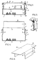
- Figure 1 shows in section transverse according to I-I, figure 2, a cable support fitted with a conforming device mounting base to the invention.
- Figure 2 shows the same set with its left portion in side view and its right portion in section along II-II, figure 1.
- Figure 3 is a view of the same assembly according to the arrow III of figure 1, with its left end fitted with a cover end and its right end devoid of any cover.
- Figure 4 is a view similar to Figure 1 showing the base being assembled in the support.
- Figure 5 is a partial perspective view of a detail known per se of the above assembly.
- Figure 6 shows in perspective a variant device mounting base capable of replace the above base and also conform to the invention.
- Each wing 5 has an intermediate level from its height a recess inward forming a jump or step 6.
- This step is advantageously created by folding wing 5 inwards around a straight line L extending in the longitudinal direction of the chute, said straight line delimiting above a lower portion or base 7 of said wing 5.
- the step 6 is extended upwards by the vertical portion remaining 8 of wing 5, which portion is shifted towards the inside of the chute from a distance equal to the projection R of the step.
- Said portion 8 ends at its top with a rim 9 folded 180 ° towards the outside of the gutter.
- the cover 3 is constituted by a central plate 10 bordered laterally by two inverted channels 11 extending longitudinally and suitable for each styling a folded edge 9 of the gutter.
- this fixing is ensured by means of fasteners, or clips, 12 each consisting of a bent metal blade (figure 5) easy to operate both for mounting and for disassembly.
- a base 14 is used here. consisting of a folded plate, preferably made of metal, which can easily be substituted for part of the cover 3.
- This base 14 includes a central plate 15 of general rectangular shape.
- this plate 15 are extended by two vertical legs 16, also rectangular, via elbow fittings 17.
- the legs 16 and the elbow fittings 17 are drawn and sized so that at the end of mounting the base 14 in a gutter 1, said legs 16 internally run along the bases 7 of the wings 5 while the bent areas 17 are arranged vertically below step 6, making everything impossible dislocation of the base 14 upwards.
- each of them is connected to a horizontal ear and flat 18 suitable for overlapping an edge adjacent to a cover 3.
- each ear 18 is connected to the plate 15 via of a panel 19 inclined at a time on this plate and on that ear.
- the angle of inclination of the panel 19 on the plate 15 is in particular of the order of 45 °, as illustrated.
- the plate 15 It is preferably on the plate 15 that are fitted the devices 13 in any desirable way, for example by gluing, welding, bolting, etc.
- the upper portions 8 with curved edges 9 of the two wings 5 can therefore deviate slightly from one of the other, elastically, according to the arrows F.
- the bases of the legs 16 can be move slightly, elastically, one from the other according to arrows G.
- the ears 18 extend across the gutter, substantially at the tops of its folded edges 9.
- the base 14 is securely fixed, without any mounting clearance, on the chute.
- the assembly obtained is reversible: to disassemble the base, just release the covers 3 by longitudinal sliding thereof, after opening the fasteners 12; such clearance makes again possible a mutual elastic spacing of the two wings 5 of the gutter, and consequently a removal of the base outside the gutter by means of displacements inverse mutual relative to those observed during the mounting.
Landscapes
- Engineering & Computer Science (AREA)
- Architecture (AREA)
- Civil Engineering (AREA)
- Structural Engineering (AREA)
- Installation Of Indoor Wiring (AREA)
- Supports For Pipes And Cables (AREA)
- Multi-Conductor Connections (AREA)
- Clamps And Clips (AREA)
- Laying Of Electric Cables Or Lines Outside (AREA)
- Details Of Indoor Wiring (AREA)
Claims (5)
- Sockel für die Befestigung von Geräten über einem Kabelhalter, mit einem U-förmigen Schacht (1) und einer abnehmbaren Abdeckung (3), wobei jeder der beiden Schenkel (5) des Schachtes einen nach innen springenden Absatz (6) aufweist, dadurch gekennzeichnet, daß dieser aus einer gebogenen Platte besteht und eine zentrale Fläche (15) umfaßt, die selbst direkt oder indirekt verbunden ist einerseits mit zwei längsparallelen, die Fläche seitlich begrenzenden Bändern (16), wobei jedes Band einen gekrümmten Abschnitt (17) verlängert, derart, daß sich dieser an den Absätzen (6) des Halters festhakt, und andererseits mit zwei glatten Ansätzen (18), die sich über die Breite des Schachtes erstrecken, parallel zur Längsrichtung desselben, wobei die Ansätze geeignet sind, die benachbarten Enden der wesentlichen Abdeckungen des Halters in anstoßender Weise zu übergreifen, wobei der gegenseitige Abstand der Bänder (16) des Sockels zugleich ein wenig kleiner als der gegenseitige Abstand der Abschnitte der Schenkel des Halters ist, die die Absätze dieser Schenkel zum Boden des Trägers hin verlängern, und ein wenig größer als der gegenseitige Abstand der in bezug zu den Absätzen oberen Abschnitte.
- Sockel nach Anspruch 1, dadurch gekennzeichnet, daß die zentrale Fläche (15) des Sockels eben und rechtwinklig ist.
- Sockel nach Anspruch 2, dadurch gekennzeichnet, daß die Längsränder der Fläche (15) durch die mit den Bändern (16) verbundenen, gekrümmten Abschnitte (17) seitlich verlängert sind, und daß ihre Querränder mit den Ansätzen (18) durch Platten (19) verbunden sind, die zugleich schräg auf der Fläche und auf den Absätzen stehen.
- Sockel nach Anspruch 3, dadurch gekennzeichnet, daß der Neigungswinkel jeder Platte (19) auf der Fläche (15) und auf den Absätzen (18) etwa 45° beträgt.
- Sockel nach einem der vorstehenden Ansprüche, dadurch gekennzeichnet, daß die Höhe jedes Bandes (16) sehr viel kleiner als die Höhe der Basis jedes Schenkels (5) des Trägers ist, der zwischen dem Boden des Trägers und dem Absatz (6) jedes Schenkels liegt.
Applications Claiming Priority (2)
| Application Number | Priority Date | Filing Date | Title |
|---|---|---|---|
| FR9411845A FR2725317B1 (fr) | 1994-10-04 | 1994-10-04 | Perfectionnements aux embases de fixation d'appareillages sur les supports de cables |
| FR9411845 | 1994-10-04 |
Publications (2)
| Publication Number | Publication Date |
|---|---|
| EP0706249A1 EP0706249A1 (de) | 1996-04-10 |
| EP0706249B1 true EP0706249B1 (de) | 1998-04-22 |
Family
ID=9467550
Family Applications (1)
| Application Number | Title | Priority Date | Filing Date |
|---|---|---|---|
| EP95402190A Expired - Lifetime EP0706249B1 (de) | 1994-10-04 | 1995-09-29 | Verbesserungen an Geräteträger-Elementen für Kabelhalter |
Country Status (5)
| Country | Link |
|---|---|
| EP (1) | EP0706249B1 (de) |
| AT (1) | ATE165479T1 (de) |
| DE (1) | DE69502158T2 (de) |
| ES (1) | ES2115331T3 (de) |
| FR (1) | FR2725317B1 (de) |
Families Citing this family (3)
| Publication number | Priority date | Publication date | Assignee | Title |
|---|---|---|---|---|
| DE10054662C2 (de) * | 2000-11-03 | 2003-07-17 | Spelsberg Guenther Gmbh Co Kg | Einbaudose für die werkzeugfreie Montage |
| FR2852156B1 (fr) * | 2003-03-07 | 2005-10-07 | Const Electr De La Seine Ces | Support de conduits en treillis. |
| FR3095558B1 (fr) | 2019-04-24 | 2021-04-30 | Niedax France | Element de fixation de couvercle pour chemin de cables |
Family Cites Families (3)
| Publication number | Priority date | Publication date | Assignee | Title |
|---|---|---|---|---|
| FR2151483A5 (de) * | 1971-08-30 | 1973-04-20 | Marielle Jean | |
| FR2390073B1 (de) * | 1977-05-06 | 1980-03-28 | Legrand Sa | |
| FR2689605B1 (fr) * | 1992-04-01 | 1994-06-17 | Seine Conctructions Electr | Perfectionnements aux attaches pour fixer les couvercles sur les gouttieres de cablage ou analogues. |
-
1994
- 1994-10-04 FR FR9411845A patent/FR2725317B1/fr not_active Expired - Fee Related
-
1995
- 1995-09-29 EP EP95402190A patent/EP0706249B1/de not_active Expired - Lifetime
- 1995-09-29 DE DE69502158T patent/DE69502158T2/de not_active Expired - Lifetime
- 1995-09-29 AT AT95402190T patent/ATE165479T1/de not_active IP Right Cessation
- 1995-09-29 ES ES95402190T patent/ES2115331T3/es not_active Expired - Lifetime
Also Published As
| Publication number | Publication date |
|---|---|
| DE69502158T2 (de) | 1998-10-15 |
| DE69502158D1 (de) | 1998-05-28 |
| FR2725317B1 (fr) | 1996-12-13 |
| FR2725317A1 (fr) | 1996-04-05 |
| EP0706249A1 (de) | 1996-04-10 |
| ES2115331T3 (es) | 1998-06-16 |
| ATE165479T1 (de) | 1998-05-15 |
Similar Documents
| Publication | Publication Date | Title |
|---|---|---|
| EP1172911B1 (de) | Kabelkanalkupplungsvorrichtung | |
| FR2799900A1 (fr) | Agrafe de retenue pour goulotte, notamment pour appareillages electriques | |
| FR2700146A1 (fr) | Perfectionnements aux dispositifs d'accrochage des bords des coiffes de coussins de sièges sur les armatures de ces sièges. | |
| FR2497611A1 (fr) | Bande de support en matiere plastique a section en u, pour supporter des conduites, des cables ou autres | |
| FR2820553A1 (fr) | Accessoire pour goulotte et ensemble comprenant un tel accessoire et une goulotte dont le socle est specialement adapte audit accessoire | |
| EP1094581B1 (de) | Durchführungszubehör für Kabelkanal | |
| EP0813663B1 (de) | Eckverbindungsvorrichtung für eine rinnenförmige leitung und eine abdeckung wie z.b. eine profilleiste, eine sockelleiste oder eine rinne, insbesondere für ein elektrisches bauteil | |
| EP0706249A1 (de) | Verbesserungen an Geräteträger-Elementen für Kabelhalter | |
| FR2689605A1 (fr) | Perfectionnements aux attaches pour fixer les couvercles sur les gouttières de câblage ou analogues. | |
| EP0414616A1 (de) | Klammerartige Abdeckungsverbindung für eine Leiste oder Rinne | |
| EP1320163B1 (de) | Immobilisierungszubehör für ein elektrisches Installationsgerät mit Direktschnappverbindung in einem Kabelrinnesockel | |
| EP0838885A1 (de) | Halteklammer für Kabelrinnen und zugehörige Kabelrinne | |
| EP2113977B1 (de) | Montagezubehör für ein Elektrogerät in einem Kabelkanal und elektrische Baugruppe bestehend aus einem Elektrogerät und solch einem Montagezubehör | |
| EP0342079B1 (de) | Verteilungskasten für Elektroinstallationen | |
| EP1150409B1 (de) | Kabelrinnenabschnitte und daraus hergestellte Kabelrinne durch Verbinbung von mindestens zwei Abschnitten und deren Herstellungsverfahren | |
| EP1432091B1 (de) | Kupplungsgarnitur für einen Kabelrinnesockel | |
| FR2725780A1 (fr) | Procede de fixation d'une buse sur un radiateur de refroidissement | |
| EP1164676A1 (de) | Vorrichtung zur Befestigung eines elektrischen Geräts auf einem Kabelkanal | |
| FR2943280A1 (fr) | Systeme de fixation d'un lecheur sur un ouvrant de vehicule | |
| FR2768268A1 (fr) | Agrafe de retenue ,notamment pour goulotte destinee a des appareillages electriques | |
| FR2873241A1 (fr) | Dispositif d'angle plat ou de derivation adaptable a differents angles formes entre des goulottes | |
| EP1707700B1 (de) | Konstruktionsrahmen einer doppelwandigen demontierbarenTrennwand | |
| EP1843439B1 (de) | Verbindungszubehörteil für eine Leitung und Einheit, die eine Leitung umfasst, die ein solches Zubehörteil aufnimmt | |
| EP1394918A1 (de) | Vorrichtung zur Befestigung eines Führungskanals unter einer Raumdecke und Kabelkanal mit solcher Vorrichtung | |
| FR2652142A1 (fr) | Perfectionnements aux eclisses de raccordement pour chemins de cables en treillis ou analogues. |
Legal Events
| Date | Code | Title | Description |
|---|---|---|---|
| PUAI | Public reference made under article 153(3) epc to a published international application that has entered the european phase |
Free format text: ORIGINAL CODE: 0009012 |
|
| AK | Designated contracting states |
Kind code of ref document: A1 Designated state(s): AT BE CH DE ES GB IT LI NL SE |
|
| 17P | Request for examination filed |
Effective date: 19960509 |
|
| GRAG | Despatch of communication of intention to grant |
Free format text: ORIGINAL CODE: EPIDOS AGRA |
|
| GRAG | Despatch of communication of intention to grant |
Free format text: ORIGINAL CODE: EPIDOS AGRA |
|
| GRAH | Despatch of communication of intention to grant a patent |
Free format text: ORIGINAL CODE: EPIDOS IGRA |
|
| 17Q | First examination report despatched |
Effective date: 19970908 |
|
| GRAH | Despatch of communication of intention to grant a patent |
Free format text: ORIGINAL CODE: EPIDOS IGRA |
|
| GRAA | (expected) grant |
Free format text: ORIGINAL CODE: 0009210 |
|
| AK | Designated contracting states |
Kind code of ref document: B1 Designated state(s): AT BE CH DE ES GB IT LI NL SE |
|
| PG25 | Lapsed in a contracting state [announced via postgrant information from national office to epo] |
Ref country code: NL Free format text: LAPSE BECAUSE OF FAILURE TO SUBMIT A TRANSLATION OF THE DESCRIPTION OR TO PAY THE FEE WITHIN THE PRESCRIBED TIME-LIMIT Effective date: 19980422 Ref country code: IT Free format text: LAPSE BECAUSE OF FAILURE TO SUBMIT A TRANSLATION OF THE DESCRIPTION OR TO PAY THE FEE WITHIN THE PRESCRIBED TIME-LIMIT;WARNING: LAPSES OF ITALIAN PATENTS WITH EFFECTIVE DATE BEFORE 2007 MAY HAVE OCCURRED AT ANY TIME BEFORE 2007. THE CORRECT EFFECTIVE DATE MAY BE DIFFERENT FROM THE ONE RECORDED. Effective date: 19980422 Ref country code: GB Free format text: LAPSE BECAUSE OF FAILURE TO SUBMIT A TRANSLATION OF THE DESCRIPTION OR TO PAY THE FEE WITHIN THE PRESCRIBED TIME-LIMIT Effective date: 19980422 Ref country code: AT Free format text: LAPSE BECAUSE OF FAILURE TO SUBMIT A TRANSLATION OF THE DESCRIPTION OR TO PAY THE FEE WITHIN THE PRESCRIBED TIME-LIMIT Effective date: 19980422 |
|
| RAP1 | Party data changed (applicant data changed or rights of an application transferred) |
Owner name: CONSTRUCTIONS ELECTRIQUES DE LA SEINE |
|
| REF | Corresponds to: |
Ref document number: 165479 Country of ref document: AT Date of ref document: 19980515 Kind code of ref document: T |
|
| REG | Reference to a national code |
Ref country code: CH Ref legal event code: EP |
|
| REF | Corresponds to: |
Ref document number: 69502158 Country of ref document: DE Date of ref document: 19980528 |
|
| REG | Reference to a national code |
Ref country code: ES Ref legal event code: FG2A Ref document number: 2115331 Country of ref document: ES Kind code of ref document: T3 |
|
| PG25 | Lapsed in a contracting state [announced via postgrant information from national office to epo] |
Ref country code: SE Free format text: LAPSE BECAUSE OF FAILURE TO SUBMIT A TRANSLATION OF THE DESCRIPTION OR TO PAY THE FEE WITHIN THE PRESCRIBED TIME-LIMIT Effective date: 19980722 |
|
| PG25 | Lapsed in a contracting state [announced via postgrant information from national office to epo] |
Ref country code: BE Free format text: LAPSE BECAUSE OF NON-PAYMENT OF DUE FEES Effective date: 19980930 |
|
| NLV1 | Nl: lapsed or annulled due to failure to fulfill the requirements of art. 29p and 29m of the patents act | ||
| GBV | Gb: ep patent (uk) treated as always having been void in accordance with gb section 77(7)/1977 [no translation filed] |
Effective date: 19980422 |
|
| PLBE | No opposition filed within time limit |
Free format text: ORIGINAL CODE: 0009261 |
|
| STAA | Information on the status of an ep patent application or granted ep patent |
Free format text: STATUS: NO OPPOSITION FILED WITHIN TIME LIMIT |
|
| BERE | Be: lapsed |
Owner name: CONSTRUCTIONS ELECTRIQUES DE LA SEINE Effective date: 19980930 |
|
| 26N | No opposition filed | ||
| PG25 | Lapsed in a contracting state [announced via postgrant information from national office to epo] |
Ref country code: LI Free format text: LAPSE BECAUSE OF NON-PAYMENT OF DUE FEES Effective date: 19990930 Ref country code: CH Free format text: LAPSE BECAUSE OF NON-PAYMENT OF DUE FEES Effective date: 19990930 |
|
| REG | Reference to a national code |
Ref country code: CH Ref legal event code: PL |
|
| PGFP | Annual fee paid to national office [announced via postgrant information from national office to epo] |
Ref country code: ES Payment date: 20110913 Year of fee payment: 17 Ref country code: DE Payment date: 20110902 Year of fee payment: 17 |
|
| PG25 | Lapsed in a contracting state [announced via postgrant information from national office to epo] |
Ref country code: DE Free format text: LAPSE BECAUSE OF NON-PAYMENT OF DUE FEES Effective date: 20130403 |
|
| REG | Reference to a national code |
Ref country code: DE Ref legal event code: R119 Ref document number: 69502158 Country of ref document: DE Effective date: 20130403 |
|
| REG | Reference to a national code |
Ref country code: ES Ref legal event code: FD2A Effective date: 20131018 |
|
| PG25 | Lapsed in a contracting state [announced via postgrant information from national office to epo] |
Ref country code: ES Free format text: LAPSE BECAUSE OF NON-PAYMENT OF DUE FEES Effective date: 20120930 |