EP0706255A1 - Kommutatorelektrische Maschine, insbesondere Gleichstromelektromotor - Google Patents
Kommutatorelektrische Maschine, insbesondere Gleichstromelektromotor Download PDFInfo
- Publication number
- EP0706255A1 EP0706255A1 EP95115537A EP95115537A EP0706255A1 EP 0706255 A1 EP0706255 A1 EP 0706255A1 EP 95115537 A EP95115537 A EP 95115537A EP 95115537 A EP95115537 A EP 95115537A EP 0706255 A1 EP0706255 A1 EP 0706255A1
- Authority
- EP
- European Patent Office
- Prior art keywords
- retaining member
- electric machine
- rotating electric
- machine according
- collector
- Prior art date
- Legal status (The legal status is an assumption and is not a legal conclusion. Google has not performed a legal analysis and makes no representation as to the accuracy of the status listed.)
- Granted
Links
- OKTJSMMVPCPJKN-UHFFFAOYSA-N Carbon Chemical compound [C] OKTJSMMVPCPJKN-UHFFFAOYSA-N 0.000 claims abstract description 46
- 229910052799 carbon Inorganic materials 0.000 claims abstract description 45
- 230000003100 immobilizing effect Effects 0.000 claims description 6
- 230000000295 complement effect Effects 0.000 claims description 4
- 239000000314 lubricant Substances 0.000 claims description 4
- 238000003780 insertion Methods 0.000 claims description 3
- 230000037431 insertion Effects 0.000 claims description 3
- 238000013519 translation Methods 0.000 claims description 2
- 239000011810 insulating material Substances 0.000 description 3
- 238000000034 method Methods 0.000 description 3
- 239000003610 charcoal Substances 0.000 description 2
- 238000013016 damping Methods 0.000 description 2
- 238000006073 displacement reaction Methods 0.000 description 2
- 239000012634 fragment Substances 0.000 description 2
- 230000014759 maintenance of location Effects 0.000 description 2
- 239000002184 metal Substances 0.000 description 2
- 229910052751 metal Inorganic materials 0.000 description 2
- 230000000717 retained effect Effects 0.000 description 2
- 238000004804 winding Methods 0.000 description 2
- 229910000859 α-Fe Inorganic materials 0.000 description 2
- OKTJSMMVPCPJKN-OUBTZVSYSA-N Carbon-13 Chemical compound [13C] OKTJSMMVPCPJKN-OUBTZVSYSA-N 0.000 description 1
- RYGMFSIKBFXOCR-UHFFFAOYSA-N Copper Chemical compound [Cu] RYGMFSIKBFXOCR-UHFFFAOYSA-N 0.000 description 1
- 238000004026 adhesive bonding Methods 0.000 description 1
- 239000004020 conductor Substances 0.000 description 1
- 239000000470 constituent Substances 0.000 description 1
- 229910052802 copper Inorganic materials 0.000 description 1
- 239000010949 copper Substances 0.000 description 1
- 238000013461 design Methods 0.000 description 1
- 229910002804 graphite Inorganic materials 0.000 description 1
- 239000010439 graphite Substances 0.000 description 1
- 239000012212 insulator Substances 0.000 description 1
- 238000012986 modification Methods 0.000 description 1
- 230000004048 modification Effects 0.000 description 1
- 210000002105 tongue Anatomy 0.000 description 1
- 238000003466 welding Methods 0.000 description 1
Images


Classifications
-
- H—ELECTRICITY
- H02—GENERATION; CONVERSION OR DISTRIBUTION OF ELECTRIC POWER
- H02K—DYNAMO-ELECTRIC MACHINES
- H02K5/00—Casings; Enclosures; Supports
- H02K5/04—Casings or enclosures characterised by the shape, form or construction thereof
- H02K5/14—Means for supporting or protecting brushes or brush holders
- H02K5/143—Means for supporting or protecting brushes or brush holders for cooperation with commutators
- H02K5/148—Slidably supported brushes
-
- H—ELECTRICITY
- H02—GENERATION; CONVERSION OR DISTRIBUTION OF ELECTRIC POWER
- H02K—DYNAMO-ELECTRIC MACHINES
- H02K2205/00—Specific aspects not provided for in the other groups of this subclass relating to casings, enclosures, supports
- H02K2205/06—Machines characterised by means for keeping the brushes in a retracted position during assembly
-
- H—ELECTRICITY
- H02—GENERATION; CONVERSION OR DISTRIBUTION OF ELECTRIC POWER
- H02K—DYNAMO-ELECTRIC MACHINES
- H02K5/00—Casings; Enclosures; Supports
- H02K5/04—Casings or enclosures characterised by the shape, form or construction thereof
- H02K5/16—Means for supporting bearings, e.g. insulating supports or means for fitting bearings in the bearing-shields
- H02K5/167—Means for supporting bearings, e.g. insulating supports or means for fitting bearings in the bearing-shields using sliding-contact or spherical cap bearings
Definitions
- the present invention relates to a rotary electrical machine with a collector such as a direct current electric motor.
- It relates more particularly to an electric machine in which there is a means of temporary retention of coals to facilitate the assembly of said machine.
- such a machine generally comprises a collector fixed to the shaft of the rotor of said machine and rotating around the axis of rotation of said rotor. It consists of a plurality of conductive strips of a conductive metal, in particular copper, separated by interstices provided with an insulator.
- Said machine also includes a carbon holder plate provided with housings, arranged substantially radially, and intended to receive carbon, made of an electrically conductive material, in particular graphite.
- Said carbon brushes are mounted in the housings with springs so as to be pushed back towards the collector, once the carbon holder plate is installed on the rotary electric machine.
- Document EP-B-0 236 254 discloses in particular an electric machine comprising a brush holder provided with housings for brushes and a movable section having the shape of a washer adapted so as to maintain the brushes in the housings in a mounting position.
- This washer is placed in such a way so that it is encountered by a part of the collector during the insertion of the rotor shaft through the brush holder so as to move said washer to release the brushes so that they come into contact with the collector .
- a drawback of this device comes from the fact that the washer is integrally connected to the brush holder by means of tabs which can be broken. Indeed, at the time of the displacement of said washer, fragments or the whole of the washer can fall inside the electric machine, then risking altering its operation or creating nuisance noises due to the displacements of said fragments to inside the machine.
- Document EP-B-0 148 702 partially solves this problem by describing an electric motor comprising a member for temporarily retaining the coals formed by a ring, carrying two axial tabs intended to close said housings in a first position, and mounted movable to rotation between said first position and a second position in which the coals are released.
- Said retaining member comprises a hook, intended to make it axially integral with the carbon holder plate, and a drive finger enabling it to be brought into its position for releasing the carbon.
- this retaining member has the drawback of complicating the carbon-holder plate since the latter must comprise, in addition to an ordinary plate, a slide with which the hook cooperates.
- said retaining member is an additional part which has no utility thereafter for the electric motor.
- a main object of the present invention is to solve the aforementioned problems.
- the subject of the present invention is a rotary electrical machine with a collector like a direct current electric motor, free from the drawbacks of the technique. anterior.
- the rotary electric collector machine in particular a direct current electric motor, comprises a carcass in which is arranged an inductor, an armature, integral with a shaft linked to said carcass by means of two bearings and also bearing a collector, said machine also comprising a charcoal holder carrying coals housed in housings, said coals being biased radially by elastic means, and a member for temporarily retaining coals which, in a first position closes, at least in part, the internal openings of said housings by maintaining the coals in a retracted position and which, in a second position releases the coals so that they come into contact with the collector, said retaining member being adapted to be encountered by a part of the armature during the insertion of the rotor shaft axially through the brush holder, characterized in that the retaining member enue comprises first and second means for immobilizing in translation relative to the carbon holder to be maintained in the first or second position.
- the temporary carbon retention member is immobilized in the electric machine, once the assembly thereof has been completed. It therefore does not risk vibrating and causing nuisance noise during the operation of said machine.
- the means for immobilizing the retaining member in the first and second positions relative to the brush holder are constituted by formally cooperating means.
- the shape cooperation means are formed by at least two notches formed on said retaining member and cooperating with a part of the carbon holder, each notch corresponding to an immobilized position.
- the retaining member is constituted by an annular disc having a central bore and extending axially by at least two tabs.
- the retaining member has three legs extending axially.
- This number of three legs ensures the best compromise between the flexibility of the retaining member and its stability.
- the notches constituting the means for temporary immobilization of the retaining member are arranged on the legs of said retaining member.
- This arrangement on the legs is the preferred arrangement of the invention because the flexibility of said legs allows rapid engagement and disengagement of the notches.
- the notches are arranged on the side of the tabs facing outwards from the retaining member.
- the carbon holder of said machine consists of a plate carrying the coals and a support of said plate, the plate and the support having a central bore for the passage of the shaft and the collector. of the rotor, and the notches of the retaining member cooperate with the edge of the bore of said support having a profile complementary to that of said edge.
- the only modification to be made to the carbon holder of the machine according to the invention relates to the profile of the central bore of the latter, which does not complicate the design with respect to a conventional carbon holder.
- the notches have a substantially V-shaped profile. This facilitates the engagement and disengagement of the notches without forcing too much on the legs of the retaining member which eliminates the risk of breakage of said paws.
- the diameter of the disc annular is greater than that of the collector and less than that of the bore of the carbon holder.
- the diameter of the bore of the retaining member is substantially greater than that of the rotor shaft of said machine.
- said retaining member does not hinder the movement of the shaft.
- the retaining member is adapted so as to serve as a deflector to prevent the lubricant from the bearing from reaching the coals or the collector of said machine.
- the retaining member is a useful part in the machine even when the assembly thereof is completed.
- Figure 1 there is shown a rotary electrical machine at two stages of its assembly. In the lower half-view, considering the orientation of Figure 1, it is shown at an intermediate stage of assembly, while in the upper half-view, it is shown complete.
- the rotary electric machine of FIG. 1 is an electric motor 1 comprising a carcass 2 on which ferrites 3 are fixed to form the stator of said motor, said carcass being closed by a cover 22.
- a rotor 4 forming the armature is mounted to rotate in said carcass by means of two bearings 6 and 7 crossed by the shaft 5 of said rotor and advantageously constituted by ball joints 8 and 9.
- the rotor 4 comprises a pack of sheets 10 around which are wound windings 11 whose ends are fixed, in particular by welding, on the lamellae of a collector 12, said collector being fixed on the shaft 5 of said rotor.
- Coals 13 and 14 are arranged in guides 15 and 16, being pushed by springs 17 and 18.
- the guides of said coals are carried by a carbon holder P consisting of a plate 19 on which the guides are mounted, said plate 19 being carried by a support 20.
- a piece 25 constituting the carbon retaining member of the invention is shown, in the lower half-view of Figure 1, in the position of holding the coals, preventing the carbon 13 from coming out of the guide 15 and allowing the introduction of the collector 12 between the coals.
- the retaining member 25 is shown in its final position when the assembly of the engine is completed.
- FIGS. 2 and 3 in which the elements similar to those of FIG. 1 have the same numbers and will not be described further.
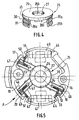
- the retaining member 25, preferably made of plastic, is made, as better visible to the Figure 4, a disc 26 pierced with a bore 27, for the passage of the shaft 5 of the rotor and of diameter substantially greater than that of said shaft 5 so as not to hinder the movement of the latter.
- the disc 26 has a diameter substantially greater than that of the collector 12.
- Said disc 26 is extended axially, in a direction perpendicular to the surface of said disc, by lugs 28a, 28b, 28c, preferably three in number, having the general shape of cylinder portions, and which are, in the example of embodiment described, of greater width on their side 29a connected to the disc 26 than on their free side 29b.
- the tabs 28a-28c of said retaining member each comprise two notches 30 and 31, located on the part directed towards the outside of the cylinder portions, the profile of said notches being substantially V-shaped. These notches are adapted to cooperate with a central bore 32 formed on the support 20 of the brush holder P and the profile of the notches is complementary to that of said bore 32.
- the retaining member 25 is positioned so that each notch 31, that located on the free side of each tab, cooperates with the bore 32 of the support 20 of the carbon holder, so as to axially immobilizing said retaining member with respect to the brush holder, in a first position.
- the height of the legs 28a-28c plus the thickness of the disc 26 is chosen to be greater than the thickness of the carbon holder P taken at its central bore 32, 34, and the thickness of the disc 26 of the member retained is greater than the thickness of the plate 19 of the brush holder plus the thickness of the guide 15, 16.
- the carbon holder P is constituted, as we have seen previously by a support 20, made of an insulating material, overmolded on a circuit 33 made up of metal electrical connection tracks, and by a plate 19, also made of insulating material, pierced with a bore 34 for the passage of the manifold and of the shaft 5 of the rotor, said bore 34 being of diameter substantially greater than that of the manifold 12.
- the two constituent elements of the carbon holder P, the plate 19 and the support 20, are assembled by means of damping blocks (shown in dotted lines 40, 41 in FIG. 5) according to a process which is not concerned here by the invention.
- the plate 19 carries guides 15, 16 of generally tubular shape, arranged substantially radially as best seen in FIG. 5, in which coals 13, 14 are adapted to slide, pushed by springs 17, 18.
- the disc 26 In the first position occupied by the retaining member 25 in FIG. 2, during assembly of the motor, the disc 26 is arranged so that its periphery 35 is in contact with the coals 13, 14 while keeping them at the inside the guides 15, 16. It should be noted that to achieve this function, the diameter of the disc 26 of the retaining member 25 must be substantially less than that of the bore 34 of the plate 19 of the carbon holder P, so as to be able to penetrate said bore, and said diameter must be greater than that of the collector 12 so that said collector can be slid between the coals without being obstructed by them.
- the manifold 12 is also shown in an intermediate position during assembly of the engine, position in which it is slid between the coals without coming into contact with them or with the retaining member 25.
- the retaining member 25 is arranged so that these are the notches 30, those located on the side of the tabs 28a-28c connecting to the disc 26, which cooperate with the bore 32 of the support 20, for axially immobilizing said retaining member in a second position, lower than the first, considering the bottom of the motor on the side of the ball 9.
- the member 25 also serves, in this final position, as a deflector for the projections of lubricant coming from the ball joint.
- the diameter of the bore 27 of the disc 26, constituting the upper part of the retaining member 25, being slightly greater than the diameter of the shaft 5, said disc 26 prevents practically any lubricant of the ball joint from polluting collector blades or coals.
- the retaining member 25 is a useful part for the operation of the engine, once the latter has been assembled.
- the carbon holder P consists, as we saw previously, of a support 20 and a plate 19, both made of insulating material.
- the plate 19 carries three tubular elements 15, 16, 42 serving to guide coals 13, 14, 43 pushed by springs 17, 18, 44.
- the plate 19 carries three coals so that the motor can rotate at two possible speeds, depending on the supply of the coals, as is known per se.
- the guides 15, 16, 42 are first fixed on the plate 19, for example by means of tongues, integrally formed with said guides and folded in corresponding orifices in the plate 19, then the plate 19, provided with its guides, is assembled on the support 20 by means of damping blocks 40, 41.
- Each damper block 40, 41 is slid radially into openings made on cylindrical sectors 45, 46 made integrally with the support 20, said damper coming to wedge the edge of the plate 19 disposed on the support, so as to immobilize the latter axially and radially with respect to the support.
- the retaining member 25 is slid into the bore 34 of the plate 19, until the notches 31, formed in the tabs 28a-28c, come to cooperate with the edge of complementary shape of the bore 32 of the support 20.
- the disc 26 of said retaining member projects above the upper surface of the plate 19 (that which is visible in FIG. 5), so as to partially closing off the internal outlet orifices of the guides 15, 16, 42, oriented towards the center side of the carbon holder.
- the retaining member 25 does not require angular indexing for its mounting, because each notch can cooperate with any part of the edge of the bore 32, this which facilitates the automation of said assembly.
- the coals 13, 14, 43 are then slid into the guides 15, 16, 42, making them enter through the openings arranged on the side of the periphery of the charcoal holder, until they come up against the member. 25.
- the springs 17, 18, 44 are then arranged in said guides, then the tabs 47, 48, 49 for closing the guides are folded, at right angles to the plate 19, so as to press the springs against coals.
- the coals have braids 50, 51, 52 for electrical connection which are then welded to the electrical circuit 33 included in the support 20.
- said carbon holder is fixed by known means, for example using screws, to the cover 22 for closing the carcass 2 of said engine.
- the armature of the motor is assembled, the assembly of which has been carried out beforehand.
- the shaft 5 fitted with the sheet pack 10, the windings 11 and the manifold 12 is introduced into the bore 27 of the disc of the retaining member 25.
- the retaining member is then immobilized in its second position when the notches 30 of the tabs 28a-28c reach the bore 32 and cooperate with its edge.
- the coals are like this released and come to bear on the collector under the thrust of the springs 17, 18, 44.
- the axial position of the armature is then adjusted so that the surface 36 of the collector does not press on the surface 37 of the retaining member. This avoids any friction between the two surfaces which could cause noise or slow down the movement of the armature.
- the carcass 2 of the motor in which the ferrites 3 have previously been fixed, by stapling or gluing, and mounted the ball joint 8 in a housing 21 formed in the bottom of said carcass, then surrounds the armature to be fixed to the cover of closure 22, for example by means of screws.
- the motor thus produced according to the invention is therefore particularly simple to assemble automatically.
- the retaining member may comprise only two tabs provided with notches, or on the contrary comprise a number greater than three.
- the notches can have a profile other than the V profile described in the embodiment above, for example a U profile.
Landscapes
- Engineering & Computer Science (AREA)
- Power Engineering (AREA)
- Motor Or Generator Current Collectors (AREA)
- Motor Or Generator Frames (AREA)
Applications Claiming Priority (2)
| Application Number | Priority Date | Filing Date | Title |
|---|---|---|---|
| FR9411929A FR2725322B1 (fr) | 1994-10-04 | 1994-10-04 | Machine electrique tournante a collecteur, notamment moteur electrique a courant continu |
| FR9411929 | 1994-10-04 |
Publications (2)
| Publication Number | Publication Date |
|---|---|
| EP0706255A1 true EP0706255A1 (de) | 1996-04-10 |
| EP0706255B1 EP0706255B1 (de) | 1998-12-02 |
Family
ID=9467611
Family Applications (1)
| Application Number | Title | Priority Date | Filing Date |
|---|---|---|---|
| EP95115537A Expired - Lifetime EP0706255B1 (de) | 1994-10-04 | 1995-10-02 | Kommutatorelektrische Maschine, insbesondere Gleichstromelektromotor |
Country Status (4)
| Country | Link |
|---|---|
| EP (1) | EP0706255B1 (de) |
| DE (1) | DE69506358T2 (de) |
| ES (1) | ES2125543T3 (de) |
| FR (1) | FR2725322B1 (de) |
Cited By (5)
| Publication number | Priority date | Publication date | Assignee | Title |
|---|---|---|---|---|
| FR2764746A1 (fr) * | 1997-06-16 | 1998-12-18 | Valeo Systemes Dessuyage | Organe de blocage des balais d'un moteur electrique pour vehicule automobile |
| WO2002050981A1 (fr) * | 2000-12-21 | 2002-06-27 | Valeo Equipements Electriques Moteur | Machine electrique a ensemble porte-balais et procede d'assemblage d'une machine electrique pourvue d'un tel ensemble |
| FR2824199A1 (fr) * | 2001-04-27 | 2002-10-31 | Valeo Equip Electr Moteur | Ensemble porte-balais pour machine electrique, telle qu'un demarreur de vehicule automobile, machine electrique et procede d'assemblage d'une machine electrique pourvue d'un tel demarreur |
| WO2004004094A1 (de) * | 2002-06-26 | 2004-01-08 | Robert Bosch Gmbh | Elektromotor mit einer halterung für mindestens zwei kohlebürsten |
| DE102011081168A1 (de) * | 2011-08-18 | 2013-02-21 | Robert Bosch Gmbh | Andrehvorrichtung und Verfahren zur Herstellung einer Andrehvorrichtung |
Families Citing this family (3)
| Publication number | Priority date | Publication date | Assignee | Title |
|---|---|---|---|---|
| DE19945788A1 (de) * | 1999-09-24 | 2001-03-29 | Valeo Auto Electric Gmbh | Elektromotor |
| FR2804553A1 (fr) * | 2000-01-27 | 2001-08-03 | Siemens Automotive Moteurs Ele | Procede d'assemblage d'un moteur electrique et moteur electrique adapte a la mise en oeuvre de ce procede |
| DE102012102814B4 (de) * | 2012-03-30 | 2024-06-06 | Valeo Wischersysteme Gmbh | Scheibenwischermotor |
Citations (2)
| Publication number | Priority date | Publication date | Assignee | Title |
|---|---|---|---|---|
| EP0148702A2 (de) | 1984-01-09 | 1985-07-17 | ACIERS ET OUTILLAGE PEUGEOT Société dite: | Elektrischer Motor, insbesondere für Fahrzeugzubehör |
| EP0236254A2 (de) | 1986-03-07 | 1987-09-09 | United Technologies Motor Systems, Inc. | Bürstenhalter für dynamoelektrische Maschine |
-
1994
- 1994-10-04 FR FR9411929A patent/FR2725322B1/fr not_active Expired - Fee Related
-
1995
- 1995-10-02 EP EP95115537A patent/EP0706255B1/de not_active Expired - Lifetime
- 1995-10-02 ES ES95115537T patent/ES2125543T3/es not_active Expired - Lifetime
- 1995-10-02 DE DE69506358T patent/DE69506358T2/de not_active Expired - Fee Related
Patent Citations (2)
| Publication number | Priority date | Publication date | Assignee | Title |
|---|---|---|---|---|
| EP0148702A2 (de) | 1984-01-09 | 1985-07-17 | ACIERS ET OUTILLAGE PEUGEOT Société dite: | Elektrischer Motor, insbesondere für Fahrzeugzubehör |
| EP0236254A2 (de) | 1986-03-07 | 1987-09-09 | United Technologies Motor Systems, Inc. | Bürstenhalter für dynamoelektrische Maschine |
Cited By (7)
| Publication number | Priority date | Publication date | Assignee | Title |
|---|---|---|---|---|
| FR2764746A1 (fr) * | 1997-06-16 | 1998-12-18 | Valeo Systemes Dessuyage | Organe de blocage des balais d'un moteur electrique pour vehicule automobile |
| WO2002050981A1 (fr) * | 2000-12-21 | 2002-06-27 | Valeo Equipements Electriques Moteur | Machine electrique a ensemble porte-balais et procede d'assemblage d'une machine electrique pourvue d'un tel ensemble |
| US6864615B2 (en) | 2000-12-21 | 2005-03-08 | Valeo Equipments Electriques Moteur | Electric machine with brush-holder assembly and method for assembling an electric machine provided with such an assembly |
| FR2824199A1 (fr) * | 2001-04-27 | 2002-10-31 | Valeo Equip Electr Moteur | Ensemble porte-balais pour machine electrique, telle qu'un demarreur de vehicule automobile, machine electrique et procede d'assemblage d'une machine electrique pourvue d'un tel demarreur |
| WO2004004094A1 (de) * | 2002-06-26 | 2004-01-08 | Robert Bosch Gmbh | Elektromotor mit einer halterung für mindestens zwei kohlebürsten |
| US7518281B2 (en) | 2002-06-26 | 2009-04-14 | Robert Bosch Gmbh | Electric motor with a housing for at least two carbon brushes |
| DE102011081168A1 (de) * | 2011-08-18 | 2013-02-21 | Robert Bosch Gmbh | Andrehvorrichtung und Verfahren zur Herstellung einer Andrehvorrichtung |
Also Published As
| Publication number | Publication date |
|---|---|
| FR2725322A1 (fr) | 1996-04-05 |
| ES2125543T3 (es) | 1999-03-01 |
| DE69506358T2 (de) | 1999-04-29 |
| EP0706255B1 (de) | 1998-12-02 |
| DE69506358D1 (de) | 1999-01-14 |
| FR2725322B1 (fr) | 1996-11-08 |
Similar Documents
| Publication | Publication Date | Title |
|---|---|---|
| EP3066750B1 (de) | Bürstenhalter einer elektrischen maschine für kraftfahrzeuganlasser, und entsprechender anlasser | |
| EP0706255B1 (de) | Kommutatorelektrische Maschine, insbesondere Gleichstromelektromotor | |
| WO2022069096A1 (fr) | Rotor de machine electrique et procede d'assemblage d'un tel rotor | |
| FR2813718A1 (fr) | Moteur electrique comprenant des moyens de fixation ameliores d'un flasque d'extremite sur une carcasse statorique | |
| EP0148702B1 (de) | Elektrischer Motor, insbesondere für Fahrzeugzubehör | |
| FR2530885A1 (fr) | Sous-ensemble d'alimentation pour moteur electrique, et moteur comprenant un tel sous-ensemble | |
| EP1193832A1 (de) | Elektromotor mit automatischer Auslösung der Kohlbürsten während des Zusammenbaus | |
| EP2901528A1 (de) | Bürstenkasten für einen bürstenhalter einer elektrischen maschine und entsprechender bürstenhalter | |
| FR2708395A1 (fr) | Platine porte-charbons pour moteur électrique à courant continu à collecteur et moteur électrique ainsi équipé. | |
| FR2548472A1 (fr) | Dispositif pour le maintien et le centrage d'une rondelle porte-balais, en cours de montage, sur une machine tournante electrique a collecteur | |
| WO2012168131A1 (fr) | Assemblage support charbon | |
| WO2018189150A1 (fr) | Moteur électrique synchrone et procédé d'assemblage de ce moteur électrique | |
| EP1925011B1 (de) | Wärmekraftmaschinenanlasserschalter mit verbesserten elektrischen verbindungsmitteln der wicklung | |
| FR2542510A1 (fr) | Porte-balais pour machine electrique tournante a collecteur | |
| EP3231067B1 (de) | Verbesserter bürstenkäfig für kraftfahrzeuganlasser und zugehöriger bürstenhalter, elektromotor und kraftfahrzeuganlasser | |
| EP2764609B1 (de) | Induktionsmotor in einem rohrförmigen stellglied und montageverfahren für diesen motor | |
| EP2764608B1 (de) | Gehäuse für einen induktionsmotor und induktionsmotor mit diesem gehäuse | |
| EP0728906A1 (de) | Elektromotor mit Ruhestrombremsvorrichtung | |
| FR3060891A1 (fr) | Machine electrique tournante comportant des elements de maintien d'aimants | |
| EP3257116A2 (de) | Bürstenhalter | |
| EP2189999B1 (de) | Kontaktgeber einer Anlassvorrichtung für Kraftfahrzeuge | |
| FR2928045A1 (fr) | Dispositif a balai destine a assurer une liaison electrique avec un collecteur dans une machine electrique tournante | |
| FR3096192A1 (fr) | Ensemble porte-balais de moteur à courant continu | |
| WO2017187052A1 (fr) | Dispositif porte-balais pour un demarreur | |
| FR3050884A1 (fr) | Ensemble porte balais pour demarreur |
Legal Events
| Date | Code | Title | Description |
|---|---|---|---|
| PUAI | Public reference made under article 153(3) epc to a published international application that has entered the european phase |
Free format text: ORIGINAL CODE: 0009012 |
|
| AK | Designated contracting states |
Kind code of ref document: A1 Designated state(s): DE ES GB IT |
|
| 17P | Request for examination filed |
Effective date: 19960926 |
|
| GRAG | Despatch of communication of intention to grant |
Free format text: ORIGINAL CODE: EPIDOS AGRA |
|
| 17Q | First examination report despatched |
Effective date: 19971020 |
|
| GRAG | Despatch of communication of intention to grant |
Free format text: ORIGINAL CODE: EPIDOS AGRA |
|
| GRAH | Despatch of communication of intention to grant a patent |
Free format text: ORIGINAL CODE: EPIDOS IGRA |
|
| GRAH | Despatch of communication of intention to grant a patent |
Free format text: ORIGINAL CODE: EPIDOS IGRA |
|
| GRAA | (expected) grant |
Free format text: ORIGINAL CODE: 0009210 |
|
| AK | Designated contracting states |
Kind code of ref document: B1 Designated state(s): DE ES GB IT |
|
| GBT | Gb: translation of ep patent filed (gb section 77(6)(a)/1977) |
Effective date: 19981202 |
|
| REF | Corresponds to: |
Ref document number: 69506358 Country of ref document: DE Date of ref document: 19990114 |
|
| ITF | It: translation for a ep patent filed | ||
| REG | Reference to a national code |
Ref country code: ES Ref legal event code: FG2A Ref document number: 2125543 Country of ref document: ES Kind code of ref document: T3 |
|
| PG25 | Lapsed in a contracting state [announced via postgrant information from national office to epo] |
Ref country code: GB Free format text: LAPSE BECAUSE OF NON-PAYMENT OF DUE FEES Effective date: 19991002 |
|
| PG25 | Lapsed in a contracting state [announced via postgrant information from national office to epo] |
Ref country code: ES Free format text: LAPSE BECAUSE OF NON-PAYMENT OF DUE FEES Effective date: 19991003 |
|
| PLBE | No opposition filed within time limit |
Free format text: ORIGINAL CODE: 0009261 |
|
| STAA | Information on the status of an ep patent application or granted ep patent |
Free format text: STATUS: NO OPPOSITION FILED WITHIN TIME LIMIT |
|
| 26N | No opposition filed | ||
| GBPC | Gb: european patent ceased through non-payment of renewal fee |
Effective date: 19991002 |
|
| PG25 | Lapsed in a contracting state [announced via postgrant information from national office to epo] |
Ref country code: DE Free format text: LAPSE BECAUSE OF NON-PAYMENT OF DUE FEES Effective date: 20000801 |
|
| REG | Reference to a national code |
Ref country code: ES Ref legal event code: FD2A Effective date: 20001113 |
|
| PG25 | Lapsed in a contracting state [announced via postgrant information from national office to epo] |
Ref country code: IT Free format text: LAPSE BECAUSE OF NON-PAYMENT OF DUE FEES Effective date: 20051002 |