EP0236254A2 - Bürstenhalter für dynamoelektrische Maschine - Google Patents
Bürstenhalter für dynamoelektrische Maschine Download PDFInfo
- Publication number
- EP0236254A2 EP0236254A2 EP87630027A EP87630027A EP0236254A2 EP 0236254 A2 EP0236254 A2 EP 0236254A2 EP 87630027 A EP87630027 A EP 87630027A EP 87630027 A EP87630027 A EP 87630027A EP 0236254 A2 EP0236254 A2 EP 0236254A2
- Authority
- EP
- European Patent Office
- Prior art keywords
- brush
- armature
- commutator
- washer
- brush holder
- Prior art date
- Legal status (The legal status is an assumption and is not a legal conclusion. Google has not performed a legal analysis and makes no representation as to the accuracy of the status listed.)
- Granted
Links
Images


Classifications
-
- H—ELECTRICITY
- H02—GENERATION; CONVERSION OR DISTRIBUTION OF ELECTRIC POWER
- H02K—DYNAMO-ELECTRIC MACHINES
- H02K5/00—Casings; Enclosures; Supports
- H02K5/04—Casings or enclosures characterised by the shape, form or construction thereof
- H02K5/14—Means for supporting or protecting brushes or brush holders
- H02K5/143—Means for supporting or protecting brushes or brush holders for cooperation with commutators
- H02K5/148—Slidably supported brushes
-
- H—ELECTRICITY
- H01—ELECTRIC ELEMENTS
- H01R—ELECTRICALLY-CONDUCTIVE CONNECTIONS; STRUCTURAL ASSOCIATIONS OF A PLURALITY OF MUTUALLY-INSULATED ELECTRICAL CONNECTING ELEMENTS; COUPLING DEVICES; CURRENT COLLECTORS
- H01R39/00—Rotary current collectors, distributors or interrupters
- H01R39/02—Details for dynamo electric machines
- H01R39/38—Brush holders
-
- H—ELECTRICITY
- H01—ELECTRIC ELEMENTS
- H01R—ELECTRICALLY-CONDUCTIVE CONNECTIONS; STRUCTURAL ASSOCIATIONS OF A PLURALITY OF MUTUALLY-INSULATED ELECTRICAL CONNECTING ELEMENTS; COUPLING DEVICES; CURRENT COLLECTORS
- H01R43/00—Apparatus or processes specially adapted for manufacturing, assembling, maintaining, or repairing of line connectors or current collectors or for joining electric conductors
- H01R43/12—Manufacture of brushes
-
- H—ELECTRICITY
- H02—GENERATION; CONVERSION OR DISTRIBUTION OF ELECTRIC POWER
- H02K—DYNAMO-ELECTRIC MACHINES
- H02K2205/00—Specific aspects not provided for in the other groups of this subclass relating to casings, enclosures, supports
- H02K2205/06—Machines characterised by means for keeping the brushes in a retracted position during assembly
Definitions
- This invention relates to dynamoelectric machines and a brush holder for securing brushes in the machines during assembly and thereafter. More particularly the present invention applies to motors and generators utilizing brushes wherein it is desirable to have a brush holder to secure the brushes in a position which facilitates assembly and which facilitates automated assembly.
- the brush riggings for motors and generators and the like vary in design, but in general consist of boxes to house the brushes, a spring means to apply pressure to the brushes to urge them against a commutator, connecting electrical leads to provide a current path to the brushes and a mounting surface to secure these elements as well as to provide some means to secure the entire assembly to the motor in such a manner as to place the brushes in a proper working relationship with the commutator.
- One of the most popular designs, especially for small fractional horsepower motors, is to utilize a molded brush card member of a one-piece construction formed from a high temperature resistant plastic.
- the member has the brush boxes formed thereon as well as various openings for securing it to the motor housing and for receiving an extending armature shaft and the commutator secured to the shaft.
- the prior riggings present problems when they are contemplated for use in an automated assembly process.
- complicated movements would have to be performed by the automation equipment to hold the brushes back in the brush box against the pressure being applied to the brushes by the spring means until such time as the commutator is positioned to receive the brushes.
- the herein-described brush holder is a molded brush card member having a displaceable section which acts to secure the brushes within the brush box until such time as the armature is assembled thereto.
- the displaceable section is designed such that upon assembly, the armature to the motor acts to displace the displaceable section thereby releasing the brushes and allowing the brush springs to urge the brushes against the commutator.
- the displaceable section is a washer-like member which serves as a thrust washer and/or an oil slinger on the armature shaft after it is displaced to release the brushes.
- Another embodiment discloses breakaway sections which merely fall to the bottom of the motor housing after they are displaced.
- a third embodiment discloses fingers which are bent relative to the brush card holder as the armature is assembled.
- An object of the present invention is to provide a unitary brush card holder for securing the brushes in a mounting position prior to assembly.
- Another object of the present invention is to provide an improved automated assembly method wherein a brush card holder secures brushes in a monitoring position allowing for automatic assembly of the armature thereto.
- a still further object of the present invention is to provide a brush card member wherein a portion of the member is displaced during assembly, said portion thereby releasing the brushes to engage the commutator of the motor.
- a yet further object of the present invention is to provide a dynamoelectric machine wherein a brush card member is formed to aid in the assembly of the motor.
- a still further object of the present invention is to provide a dynamoelectric machine wherein a displaced section of a brush card member serves as a thrust washer and/or oil slinger on the armature shaft.
- Another object of the present invention is to provide a safe, economical, easy to assemble and reliable dynamoelectric machine and method of assembly.
- a dynamoelectric machine of the type having brushes that contact a commutator position on an armature shaft of an armature.
- a brush holder is provided for positioning the brushes to engage the commutator, said brush holder being formed to provide a displaceable section for securing the brushes in a mounting position, said displaceable section being configured such that upon assembly of the motor, the armature shaft is inserted through the brush holder and a portion of the armature engages the displaceable section thereby displacing the section and releasing the brushes to engage a portion of the commutator of the armature.
- a brush holder member for a dynamoelectric machine having an armature including an armature shaft formed to receive at least one cavity for receiving and positioning a brush with respect to a commutator.
- the brush holder includes a washer portion having a center opening formed from a portion of the holder, the outer circumference of which extends over a portion of the cavity to prevent movement of the brush toward a center position and said washer portion being secured to the remainder of the brush holder portion by breakaway tabs.
- a method of assembly of a dynamoelectric machine of the type having a housing and brushes that engage a commutator located on an armature having an armature shaft includes the steps of securing a brush holder having at least one brush mounted for reciprocating movement to the housing, said brush holder including a brush spring for urging the brush in a first direction and a displaceable section extending to engage the brush to prevent further movement in the first direction.
- the armature is then inserted into the housing and as the armature is displaced, the armature engages the displaceable section of the brush holder to displace it to the final assembled position, said armature displacing the displaceable section thereby allowing the brush spring to urge the brush downwardly against the commutator of the armature.
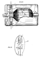
- a dynamoelectric machine which is a motor having a housing 1 with permanent magnets 2 secured therein. Armature 3 is supported to rotate within the housing by bearings 4 and 5.
- a brush card 6 defines brush card boxes having cavities 7 and 8 which hold and position brushes 9 and 10. The brushes are held in the cavities for reciprocating motion.
- Brush springs 18 and 19 are positioned to urge the brushes 7 and 8 inwardly against commutator 11 of the armature after the motor is assembled. In this position, current is supplied from conductors 12 and 13 through the brushes to the commutator to windings 15 of the armature.
- Washer 14 is shown positioned on the armature on shaft 60 between the commutator and bearing 4 and serves as a thrust washer during motor operation. The washer further serves to control end play of the armature by eliminating axial slack between the armature and the housing. Prior to assembly, washer 14 was an integral portion of the brush card as may be seen in Figure 2.
- brush card 6 which in a cutaway portion shows brush box cavity 7 in which brush 9 is mounted for reciprocating motion.
- Brush spring 18 is shown for urging brush 9 inwardly.
- Conductors 12 and 13 are shown connected to the appropriate brush.
- washer 14 is cylindrical in configuration having center opening 16 sized to the received armature shaft 60.
- Center opening 16 sized to the received armature shaft 60.
- Within the exterior of washer 14 are located circumferentially-extended slots 42 which, together with washer 14 and remainder of brush card 6 serve to define tabs 40 which secure washer 14 to the remainder of brush card 6.
- Slots 42 at the radially-outward circumference define commutator opening 44.
- Commutator opening 44 is sized to allow commutator 11 to be inserted therein.
- Washer 14 is shown in the mounting position wherein it serves to block the inward displacement of brush 9 in Figure 2.
- shaft 60 is inserted through opening 16 during assembly, the armature is then in position for being displaced to separate the washer from the remainder of the brush card.
- the tabs break and the washer is displaced to the position shown in Figure 1 between the commutator and bearing 4.
- the spring urges the brush inwardly to engage the exterior surface of commutator 11 as is desired.
- FIG. 7 specifically shows an arrangement where conductor 12 is inserted through grommet 21 secured within housing 1 of the motor. Conductor 12 is secured to plate 22 by solder or by mechanically crimping brush shunt 20 that extends up through brush spring 18 to connector plate 22.
- Shunt 20 forms an electrical connecti on between conductor 12 and brush 9.
- Plate 22 provides convenient means to make electrical connection between the outside conductor and a brush shunt. Further the plate provides a stop means for the brush spring which will be in the compressed state as it urges the brush towards the center of the brush card.
- a connector plate tab 23 is provided for engaging lip 24 of the brush box defined by the card member such that the connector plate may be secured thereto. This is but one arrangement of securing a brush and making electrical connection thereto. Other similar arrangements are well known.
- FIG. 2 again shows the brush holder assembly prior to assembly into the motor.
- armature shaft 60 is inserted into opening 16 of the brush card.
- the diameter of the opening is preferably such that a slip fit exists between the shaft and opening 60 of the washer.
- the radially-extending face of the commutator comes into contact with the washer, and, as the pressure is applied by the motor assembly equipment, the washer breaks away from the brush card and travels with the commutator as the assembly operation of the motor continues.
- the washer now rests against the face of the commutator and may serve as a thrust surface for the armature during axial loading and may serve to control end play or axial movement of the armature within the motor housing.
- Another important function of the washer is to sling oil that characteristically seeps from oil impregnated bearing 4 or from other external sources to prevent that oil from creeping down the armature shaft and contaminating the brushes.
- a separate washer was of necessity pressed onto the shaft to sling the oil off the shaft before it reached the brushes. It has been found that oil causes the brushes to gum up and stick in the brush boxes or causes other electrical problems between the brushes and the commutator which cannot be tolerated if effective motor operation is required.
- FIG 3 shows an alternative embodiment wherein brush card 25 is substituted for brush card 6 of Figure 1.
- the remaining elements of the basic motor are labeled the same and are identical to the elements in Figure 1.
- Brush card 25 is formed with a plurality of breakaway sections 26 each having a step portion 27 that functions as a shelf upon which brushes 8 and 9 rest prior to assembly.
- this brush card provides for the step section to be broken away by the commutator during assembly such that the breakaway section separates into several pieces as shown in Figure 3. These broken-away pieces fall harmlessly into a space between the brush card and end cap 28 of the motor and do not interfere with operation of the motor.
- Brush card 29 in Figure 5 includes a pair of projecting fingers 30 and 31, each of which has a projection 34 and 36 which extends inwardly and includes a contact surface 32 and 33 to engage respective brushes 9 and 10 to secure them in a mounting position.
- Projections 36 and 34 extend inwardly and at contact surfaces 32 and 33 engage the brushes such that the springs may not urge the brushes inwardly.
- the radially-extending face of the commutator engages the projections and displaces them to the left as shown in Figure 5.
- the fingers are bent and the retention of the brushes in the mounting position is released.
- the brush springs then urge the brushes inwardly to engage the commutator surface in the desired final configuration as shown in Figure 5.
- they may act to absorb some axial load exerted by the face of the commutator against th e fingers when the motor is operated.
Landscapes
- Engineering & Computer Science (AREA)
- Power Engineering (AREA)
- Motor Or Generator Current Collectors (AREA)
- Dc Machiner (AREA)
- Manufacture Of Motors, Generators (AREA)
Applications Claiming Priority (2)
| Application Number | Priority Date | Filing Date | Title |
|---|---|---|---|
| US06/837,108 US4694214A (en) | 1986-03-07 | 1986-03-07 | Brush holder for dynamoelectric machines |
| US837108 | 1986-03-07 |
Publications (3)
| Publication Number | Publication Date |
|---|---|
| EP0236254A2 true EP0236254A2 (de) | 1987-09-09 |
| EP0236254A3 EP0236254A3 (en) | 1988-03-30 |
| EP0236254B1 EP0236254B1 (de) | 1993-09-22 |
Family
ID=25273534
Family Applications (1)
| Application Number | Title | Priority Date | Filing Date |
|---|---|---|---|
| EP87630027A Revoked EP0236254B1 (de) | 1986-03-07 | 1987-02-26 | Bürstenhalter für dynamoelektrische Maschine |
Country Status (5)
| Country | Link |
|---|---|
| US (1) | US4694214A (de) |
| EP (1) | EP0236254B1 (de) |
| CA (1) | CA1271803A (de) |
| DE (2) | DE236254T1 (de) |
| MX (1) | MX167435B (de) |
Cited By (8)
| Publication number | Priority date | Publication date | Assignee | Title |
|---|---|---|---|---|
| US5495657A (en) * | 1994-04-08 | 1996-03-05 | Siemens Aktiengesellschaft | Method for producing a commutator motor |
| FR2725322A1 (fr) * | 1994-10-04 | 1996-04-05 | Valeo Systemes Dessuyage | Machine electrique tournante a collecteur, notamment moteur electrique a courant continu |
| WO1996027925A1 (en) * | 1995-03-07 | 1996-09-12 | The Whitaker Corporation | Electrical motor assembly and contact for use therewith |
| GB2299218A (en) * | 1995-03-20 | 1996-09-25 | Otter Controls Ltd | Retaining brushes during assembly of commutator |
| FR2746973A1 (fr) * | 1996-03-29 | 1997-10-03 | Valeo Systemes Dessuyage | Ensemble comprenant une platine porte-balais pour machine el ectrique tournante et un organe de blocage des balais |
| EP0778655A3 (de) * | 1995-12-07 | 1998-04-01 | Marquardt GmbH | Verstellvorrichtung für die Kohlebürsten an einem Elektromotor |
| US6680556B2 (en) | 2000-01-29 | 2004-01-20 | Schunk Metall Und Kunststoff Gmbh | Base plate for a carbon brush including means for engaging and disengaging the brush |
| DE10355982A1 (de) * | 2003-11-27 | 2005-06-30 | Valeo Motoren Und Aktuatoren Gmbh | Bürstenhalter für Elektromotoren sowie Elektromotor mit einem solchen Bürstenhalter |
Families Citing this family (35)
| Publication number | Priority date | Publication date | Assignee | Title |
|---|---|---|---|---|
| US4774754A (en) * | 1986-03-07 | 1988-10-04 | United Technologies Electro Systems, Inc. | Displaceable brush holder for dynamoelectric machine assembly |
| FR2615666B1 (fr) * | 1987-05-21 | 1989-08-18 | Peugeot Aciers Et Outillage | Plaque porte-balais perfectionnee notamment pour moteur electrique |
| US5113104A (en) * | 1989-10-19 | 1992-05-12 | General Electric Company | Structured product dynamoelectric machine |
| US5006747A (en) * | 1990-04-02 | 1991-04-09 | United Technologies Motor Systems, Inc. | Dynamoelectric machine brush rigging and method of assembly |
| US5172465A (en) * | 1990-04-02 | 1992-12-22 | United Technologies Motor Systems, Inc. | Method of assembling dynamoelectric machine brush rigging |
| US5047679A (en) * | 1990-08-30 | 1991-09-10 | Baader Edward J | Casing for a small motor assembly |
| US5440186A (en) * | 1993-09-13 | 1995-08-08 | United Technologies Automotive, Inc. | Motor with isolated brush card assembly |
| US5495134A (en) * | 1993-09-20 | 1996-02-27 | Itt Automotive Electrical Systems Inc. | Dynamoelectric brush holder |
| US5444320A (en) * | 1993-10-29 | 1995-08-22 | Eaton Stamping Company | Electric motor with brush retainer |
| US5471107A (en) * | 1993-12-30 | 1995-11-28 | Rawls; Earl W. | End cap and brush holder assembly for dynamoelectric machine |
| US5490802A (en) * | 1994-02-24 | 1996-02-13 | United Technologies Automotive, Inc. | Secondary terminal lock plug through stuffer |
| US5485049A (en) * | 1994-05-25 | 1996-01-16 | United Technologies Motor Systems, Inc. | Multi-speed motor |
| US5747911A (en) * | 1994-09-30 | 1998-05-05 | Itt Automotive Electrical Systems, Inc. | Brush holder |
| US5772274A (en) * | 1995-01-31 | 1998-06-30 | Asc Incorporated | Motorized drive system for a convertible roof of an automotive vehicle |
| JPH114570A (ja) * | 1997-06-11 | 1999-01-06 | Hitachi Ltd | 永久磁石界磁スタータモータ |
| FR2764746B1 (fr) * | 1997-06-16 | 1999-09-03 | Valeo Systemes Dessuyage | Organe de blocage des balais d'un moteur electrique pour vehicule automobile |
| DE19821053C2 (de) * | 1998-05-11 | 2003-01-23 | Siemens Ag | Kommutatormotor mit Montage-Rückhalterung der Bürsten |
| US5969450A (en) * | 1998-09-30 | 1999-10-19 | Ryobi North America Inc. | Armature assembly with creepage shield |
| FR2824199B1 (fr) * | 2001-04-27 | 2003-05-30 | Valeo Equip Electr Moteur | Ensemble porte-balais pour machine electrique, telle qu'un demarreur de vehicule automobile, machine electrique et procede d'assemblage d'une machine electrique pourvue d'un tel demarreur |
| WO2002050962A1 (fr) * | 2000-12-21 | 2002-06-27 | Valeo Equipements Electriques Moteur | Ensemble porte-balais pour machine electrique |
| US6924577B2 (en) * | 2003-01-13 | 2005-08-02 | Energy Conversion Systems Holdings, Llc | Brush box assembly |
| FR2853460B1 (fr) * | 2003-04-07 | 2005-06-10 | Valeo Systemes Dessuyage | Collecteur pour moteur electrique |
| US7121445B2 (en) * | 2003-04-22 | 2006-10-17 | Credo Technology Corporation | Power tool housing |
| DE10342222A1 (de) * | 2003-09-11 | 2005-05-04 | K Tec Kunststoffverarbeitung G | Topf- oder becherförmiger Träger |
| FR2865865A1 (fr) * | 2004-01-30 | 2005-08-05 | Arvinmeritor Light Vehicle Sys | Boitier de collecteur pour moteur electrique |
| US6998754B2 (en) * | 2004-03-05 | 2006-02-14 | Energy Conversion Systems Holdings, Llc | Brush assemblies |
| US20060055276A1 (en) * | 2004-09-16 | 2006-03-16 | O'donnell Steven B | Keyed motor brushes |
| FR2897992A1 (fr) * | 2006-02-24 | 2007-08-31 | Arvinmeritor Light Vehicle Sys | Dispositif d'assemblage pour moteur electrique. |
| US7466056B2 (en) | 2006-10-06 | 2008-12-16 | Remi International, Inc | Dynamoelectric machine brush holder assembly and method |
| US7696666B2 (en) | 2006-10-06 | 2010-04-13 | Remy Technologies, L.L.C. | Dynamoelectric machine grommet |
| US7705512B2 (en) | 2006-10-06 | 2010-04-27 | Remy International, Inc. | Dynamoelectric machine conductor |
| US20150076936A1 (en) | 2013-08-09 | 2015-03-19 | Black & Decker Inc. | Brush assembly having improved brush profile for an electric motor |
| US9991770B2 (en) | 2013-08-09 | 2018-06-05 | Black & Decker Inc. | Spring post for brush card for a power tool |
| US9866078B2 (en) | 2014-01-29 | 2018-01-09 | Black & Decker Inc. | Brush assembly mount |
| CN115986513A (zh) * | 2022-12-30 | 2023-04-18 | 厦门宏发汽车电子有限公司 | 电刷板和电机 |
Family Cites Families (10)
| Publication number | Priority date | Publication date | Assignee | Title |
|---|---|---|---|---|
| US3087081A (en) * | 1957-11-25 | 1963-04-23 | Ford Motor Co | Dynamoelectric machine |
| US3026432A (en) * | 1960-07-01 | 1962-03-20 | Ford Motor Co | Dynamoelectric machine |
| US3716735A (en) * | 1971-08-25 | 1973-02-13 | Stackpole Carbon Co | Electrical brush assembly |
| US4293789A (en) * | 1979-09-10 | 1981-10-06 | General Motors Corporation | Dynamoelectric machine brush rigging |
| US4423549A (en) * | 1979-09-10 | 1984-01-03 | General Motors Corporation | Method of assembling dynamoelectric machine brushes |
| US4498230A (en) * | 1982-01-08 | 1985-02-12 | Black & Decker Inc. | Assembling brush box sub-assemblies in electric motors |
| DE3227199A1 (de) * | 1982-07-21 | 1984-01-26 | Robert Bosch Gmbh, 7000 Stuttgart | Elektromotor, insbesondere zum antreiben von hilfsaggregaten in kraftfahrzeugen |
| DE3230666C2 (de) * | 1982-08-18 | 1986-04-10 | SWF Auto-Electric GmbH, 7120 Bietigheim-Bissingen | Elektrische Maschine, insbesondere Elektromotor |
| US4613781A (en) * | 1983-09-09 | 1986-09-23 | Black & Decker Inc. | End cap assembly and brush box an electric motor |
| FR2558018B1 (fr) * | 1984-01-09 | 1988-07-15 | Peugeot Aciers Et Outillage | Moteur electrique, notamment pour accessoire de vehicule et son procede de montage |
-
1986
- 1986-03-07 US US06/837,108 patent/US4694214A/en not_active Expired - Lifetime
-
1987
- 1987-02-17 CA CA000529923A patent/CA1271803A/en not_active Expired
- 1987-02-26 DE DE198787630027T patent/DE236254T1/de active Pending
- 1987-02-26 EP EP87630027A patent/EP0236254B1/de not_active Revoked
- 1987-02-26 DE DE87630027T patent/DE3787479T2/de not_active Revoked
- 1987-03-06 MX MX005491A patent/MX167435B/es unknown
Cited By (11)
| Publication number | Priority date | Publication date | Assignee | Title |
|---|---|---|---|---|
| US5495657A (en) * | 1994-04-08 | 1996-03-05 | Siemens Aktiengesellschaft | Method for producing a commutator motor |
| FR2725322A1 (fr) * | 1994-10-04 | 1996-04-05 | Valeo Systemes Dessuyage | Machine electrique tournante a collecteur, notamment moteur electrique a courant continu |
| EP0706255A1 (de) | 1994-10-04 | 1996-04-10 | Valeo Systemes D'essuyage | Kommutatorelektrische Maschine, insbesondere Gleichstromelektromotor |
| WO1996027925A1 (en) * | 1995-03-07 | 1996-09-12 | The Whitaker Corporation | Electrical motor assembly and contact for use therewith |
| US5915988A (en) * | 1995-03-07 | 1999-06-29 | The Whitaker Corporation | Contact for electrical motors |
| GB2299218A (en) * | 1995-03-20 | 1996-09-25 | Otter Controls Ltd | Retaining brushes during assembly of commutator |
| GB2299218B (en) * | 1995-03-20 | 1999-06-30 | Otter Controls Ltd | Improvements relating to dynamoelectric machines |
| EP0778655A3 (de) * | 1995-12-07 | 1998-04-01 | Marquardt GmbH | Verstellvorrichtung für die Kohlebürsten an einem Elektromotor |
| FR2746973A1 (fr) * | 1996-03-29 | 1997-10-03 | Valeo Systemes Dessuyage | Ensemble comprenant une platine porte-balais pour machine el ectrique tournante et un organe de blocage des balais |
| US6680556B2 (en) | 2000-01-29 | 2004-01-20 | Schunk Metall Und Kunststoff Gmbh | Base plate for a carbon brush including means for engaging and disengaging the brush |
| DE10355982A1 (de) * | 2003-11-27 | 2005-06-30 | Valeo Motoren Und Aktuatoren Gmbh | Bürstenhalter für Elektromotoren sowie Elektromotor mit einem solchen Bürstenhalter |
Also Published As
| Publication number | Publication date |
|---|---|
| DE3787479D1 (de) | 1993-10-28 |
| EP0236254A3 (en) | 1988-03-30 |
| DE236254T1 (de) | 1988-02-25 |
| US4694214A (en) | 1987-09-15 |
| MX167435B (es) | 1993-03-23 |
| DE3787479T2 (de) | 1994-01-20 |
| EP0236254B1 (de) | 1993-09-22 |
| CA1271803A (en) | 1990-07-17 |
Similar Documents
| Publication | Publication Date | Title |
|---|---|---|
| US4694214A (en) | Brush holder for dynamoelectric machines | |
| US4774754A (en) | Displaceable brush holder for dynamoelectric machine assembly | |
| US6020660A (en) | Dynamoelectric machine | |
| US5006747A (en) | Dynamoelectric machine brush rigging and method of assembly | |
| US6445097B1 (en) | Method for assembling and electrical connector assembly for a power tool | |
| EP0142237B1 (de) | Komponenten elektrischer Motoren | |
| EP0863602B1 (de) | Läufer für einen Elektromotor | |
| EP0638968B1 (de) | Anordnung einer zweiteiligen Endkappe | |
| US3955113A (en) | Brush holder with means for limiting travel of brush spring | |
| US4746828A (en) | Molded electric motor housing and brush holder unit | |
| US5281876A (en) | Miniature motor | |
| US4157483A (en) | Brush mounting for dynamo-electric machine | |
| US5747911A (en) | Brush holder | |
| US5373209A (en) | Assembled commutator | |
| US6909218B2 (en) | End cap and brush box assembly | |
| US5679996A (en) | Assembled commutator | |
| US7531938B2 (en) | Insertable brush holder assembly for electric motor | |
| JP2004537152A (ja) | 密閉圧縮機のモータの電気コネクタおよびその製造プロセス | |
| US5172465A (en) | Method of assembling dynamoelectric machine brush rigging | |
| EP1168575B1 (de) | Sterngeschalteter Läufer | |
| EP1124306B1 (de) | Bürstenhalteranordnung | |
| US4757602A (en) | Method for installing a collector ring assembly | |
| GB2094561A (en) | Electric motor brush gear | |
| US6867529B2 (en) | AC generator for vehicle | |
| NO159224B (no) | Elektrisk tilkoblingsinnretning for en elektrisk ledende boerstehylse som opptar en kullboerste. |
Legal Events
| Date | Code | Title | Description |
|---|---|---|---|
| PUAI | Public reference made under article 153(3) epc to a published international application that has entered the european phase |
Free format text: ORIGINAL CODE: 0009012 |
|
| AK | Designated contracting states |
Kind code of ref document: A2 Designated state(s): DE FR IT |
|
| ITCL | It: translation for ep claims filed |
Representative=s name: RICCARDI SERGIO & CO. |
|
| EL | Fr: translation of claims filed | ||
| PUAL | Search report despatched |
Free format text: ORIGINAL CODE: 0009013 |
|
| DET | De: translation of patent claims | ||
| AK | Designated contracting states |
Kind code of ref document: A3 Designated state(s): DE FR IT |
|
| 17P | Request for examination filed |
Effective date: 19880509 |
|
| 17Q | First examination report despatched |
Effective date: 19910130 |
|
| RAP1 | Party data changed (applicant data changed or rights of an application transferred) |
Owner name: UNITED TECHNOLOGIES MOTOR SYSTEMS, INC. |
|
| GRAA | (expected) grant |
Free format text: ORIGINAL CODE: 0009210 |
|
| AK | Designated contracting states |
Kind code of ref document: B1 Designated state(s): DE FR IT |
|
| ET | Fr: translation filed | ||
| REF | Corresponds to: |
Ref document number: 3787479 Country of ref document: DE Date of ref document: 19931028 |
|
| ITF | It: translation for a ep patent filed | ||
| PLBI | Opposition filed |
Free format text: ORIGINAL CODE: 0009260 |
|
| 26 | Opposition filed |
Opponent name: SCHUNK MOTORENSYSTEME GMBH Effective date: 19940622 |
|
| PGFP | Annual fee paid to national office [announced via postgrant information from national office to epo] |
Ref country code: DE Payment date: 19960124 Year of fee payment: 10 |
|
| PGFP | Annual fee paid to national office [announced via postgrant information from national office to epo] |
Ref country code: FR Payment date: 19960201 Year of fee payment: 10 |
|
| RDAH | Patent revoked |
Free format text: ORIGINAL CODE: EPIDOS REVO |
|
| RDAG | Patent revoked |
Free format text: ORIGINAL CODE: 0009271 |
|
| STAA | Information on the status of an ep patent application or granted ep patent |
Free format text: STATUS: PATENT REVOKED |
|
| 27W | Patent revoked |
Effective date: 19960416 |
|
| PLAB | Opposition data, opponent's data or that of the opponent's representative modified |
Free format text: ORIGINAL CODE: 0009299OPPO |