EP0706324B1 - Verfahren und vorrichtung zum öffnen und schliessen von backzangen in einem durchlaufofen - Google Patents
Verfahren und vorrichtung zum öffnen und schliessen von backzangen in einem durchlaufofen Download PDFInfo
- Publication number
- EP0706324B1 EP0706324B1 EP95914580A EP95914580A EP0706324B1 EP 0706324 B1 EP0706324 B1 EP 0706324B1 EP 95914580 A EP95914580 A EP 95914580A EP 95914580 A EP95914580 A EP 95914580A EP 0706324 B1 EP0706324 B1 EP 0706324B1
- Authority
- EP
- European Patent Office
- Prior art keywords
- baking
- mold
- closing
- oven
- removal
- Prior art date
- Legal status (The legal status is an assumption and is not a legal conclusion. Google has not performed a legal analysis and makes no representation as to the accuracy of the status listed.)
- Expired - Lifetime
Links
- 238000000034 method Methods 0.000 title claims description 22
- 230000033001 locomotion Effects 0.000 claims description 35
- 238000001514 detection method Methods 0.000 claims description 27
- 230000005540 biological transmission Effects 0.000 claims description 24
- 238000010438 heat treatment Methods 0.000 claims description 5
- 238000000465 moulding Methods 0.000 claims description 3
- 238000003825 pressing Methods 0.000 claims description 3
- 238000004519 manufacturing process Methods 0.000 claims description 2
- 230000003213 activating effect Effects 0.000 abstract 2
- 230000008901 benefit Effects 0.000 description 4
- 230000002411 adverse Effects 0.000 description 3
- 230000005484 gravity Effects 0.000 description 3
- 230000007246 mechanism Effects 0.000 description 2
- 230000002035 prolonged effect Effects 0.000 description 2
- 239000006173 Good's buffer Substances 0.000 description 1
- 229920002472 Starch Polymers 0.000 description 1
- 230000009471 action Effects 0.000 description 1
- 230000006978 adaptation Effects 0.000 description 1
- 239000007900 aqueous suspension Substances 0.000 description 1
- 238000004140 cleaning Methods 0.000 description 1
- 238000001816 cooling Methods 0.000 description 1
- 230000008569 process Effects 0.000 description 1
- 230000008439 repair process Effects 0.000 description 1
- 230000000717 retained effect Effects 0.000 description 1
- 230000035939 shock Effects 0.000 description 1
- 235000019698 starch Nutrition 0.000 description 1
- 239000008107 starch Substances 0.000 description 1
Images


Classifications
-
- A—HUMAN NECESSITIES
- A21—BAKING; EDIBLE DOUGHS
- A21B—BAKERS' OVENS; MACHINES OR EQUIPMENT FOR BAKING
- A21B5/00—Baking apparatus for special goods; Other baking apparatus
- A21B5/02—Apparatus for baking hollow articles, waffles, pastry, biscuits, or the like
- A21B5/023—Hinged moulds for baking waffles
Definitions
- the invention relates to a method for manufacturing products in a series of baking molds to be passed through an oven, which baking molds comprise at least two baking sections movable relative to each other, wherein in a baking cycle the baking mold is successively opened, filled, closed and locked in a closing station, guided along a number of guideways extending through the oven, and opened and emptied in a removal station.
- Such a method is known from German Offenlegungsschrift 39 34 881.
- a series a baking molds linked through chains are passed through an oven.
- Each baking mold is filled with an amount of dough in a filling station, is passed on to a closing station and is closed and locked there, is passed through a baking zone where the dough is baked and is then guided into a removal station where the baking mold is unlocked and opened and the baked product is removed from the baking mold. Then the baking mold is guided into the filling station again in opened condition.
- closure guiding means are stationarily arranged in the path of travel of the series of baking molds, in such a manner that the baking molds can be guided between and through them.
- the position of the closure guiding means is such that the sections of the baking mold are thereby pressed into the closed position when a baking mold is pulled between and through the closure guiding means by means of the chain, so that a lock can be provided.
- the closure guiding means accordingly constitute a fyke net of fixed shape and fixed position.
- the movements of the mold sections relative to each other are caused on the one hand by stationary operating means, such as the closure guiding means and the guide rail, and on the other by gravity and tension being built up in the mold during closure and baking of the product. Because the operating means are arranged stationarily, the movements of the mold sections cannot be accurately controlled and the forces occurring in the process cannot be dosed. This will give rise to large, highly varying loads.
- the force which is applied to the mold by the closure guiding means will always be inversely proportional to the fixed distance between the closure guiding means and the thickness of the mold in the closed condition. If, for instance, a mold has become thinner through wear, the force exerted thereon by the closure guiding means will be smaller than in the case of a new, thicker mold, and if a mold, for instance as a result of soiling of the land areas, is thicker in the closed condition than is normal, the force applied will be greater.
- a greater force has as a direct consequence that the driving chain will have to exert a greater pulling force on the mold in order to pass the mold through the fyke, which will give rise to greater wear of the driving chain and the driving means.
- the closure guiding means are required to produce a greater force, these means and the mold will be subject to greater wear.
- the baking mold cannot be moved through the fyke, so that the mold, the closure guiding means or the chain are damaged and the oven comes to a halt.
- the oven is at a standstill, at least the baking molds and products present in the oven will burn, causing substantial economic damage.
- the mold is thinner than is normal, the mold is not pressed shut to a sufficient extent by the closure guiding means, so that the locking of the baking mold is adversely affected and wear of the locking means is increased or even breakage of the locking means may occur.
- the baking mold will open in the oven, so that the series of baking molds will jam in the oven and the baking molds and products will burn as a result.
- the closure of the baking molds is insufficient, so that the quality of the baked products is adversely affected.
- the object of the invention is to provide a method of the type described in the preamble, whereby the disadvantages mentioned are avoided but the advantages are retained.
- the method according to the invention is characterized in that at least a part of the movements of the baking sections relative to each other are controlled by actuator means movable relative to the baking mold under active control, which, for controlling the movements of the baking sections relative to each other, transmit to the baking sections a force which is directed in the closing direction.
- the actuator means are movably arranged relative to the baking molds, variations in the thickness of the molds can be simply accommodated. Moreover, the actuator means can be positioned relative to the mold in such a manner that at any time precisely the desired force is transmitted to the mold, both with regard to the movements of the different mold sections relative to each other and with regard to the movements of the mold in the oven. As a result, the movements of the mold sections can be well controlled and the forces arising can be accurately controlled, so that the load on and wear of the different oven parts and mold parts is minimal, regardless of the molds used. Moreover, it is thus ensured that the closure and locking of the baking molds is always optimal, so that the products always meet the quality requirements set. Unlike the stationarily arranged operating means, the movable actuator means accordingly have the advantage that the mold sections are moved under active control by the actuator means.
- the occurrent tensions and loads, and particularly the variations therein, are largest when using relatively cold molds, which cannot yet be used for baking products.
- these molds are also passed through the oven while they are in cold condition, and each time opened, closed, locked and unlocked. This gives rise to substantial loads on and wear of the different parts.
- the baking molds are therefore preheated in the oven prior to being used for baking the moldings, the baking molds being closed and locked and then passed through the oven a number of times in succession without being unlocked or opened, it being preferred that during the heating of the baking molds the actuator means are moved out of the path of movement of the baking molds.
- the baking molds may also be circulated a number of times in comparable manner while in unlocked condition.
- the invention further relates to an oven comprising a series of baking molds to be passed in succession through the oven, which oven comprises at least a closing station, a removal station and a baking zone, each baking mold comprising a first and a second baking section, the first baking section comprising guide means by which the baking mold can be guided along a number of guideways extending through the oven, actuator means being provided for pressing the mold sections in the closing direction, with locking means and lock operating means being provided which are arranged for locking and unlocking the baking mold.
- the actuator means comprise a first actuator comprising closing pressure means and closure support means movable relative to each other between a first position wherein the baking mold can be moved substantially freely between and through the closing pressure means and the closure support means, and a second position wherein the baking mold in the closed condition, prior to being locked, is or can be brought into contact, under a closing bias, simultaneously with the closing pressure means and the closure support means.
- the baking mold can be moved therebetween by simply moving forward the series of baking molds, without this requiring any additional force.
- the actuator means do not exert any force on the baking mold.
- the closing pressure means and the closure support means are moved into the second position.
- a force in the closing direction is exerted on the mold sections that the locking means can be simply operated without involving any wear.
- the closing pressure means and the closure support means are preferably moved back in the direction of the first position, whereafter the baking mold can be moved freely from between them.
- the actuator means moreover comprise a second actuator comprising removal pressure means and removal support means movable relative to each other between a first position wherein the baking mold can be moved substantially freely between and through the removal pressure means and the removal support means, and a second position wherein the baking mold in closed condition, prior to being unlocked, is or can be brought into contact simultaneously with the demolding pressure means and the removal support means, biassed in a closing direction, with means being included for the controlled opening of the baking mold subsequent to unlocking.
- the second actuator means are preferably included directly before or in the removal station.
- the removal pressure means and the removal support means are movable into a first position wherein the baking mold can be moved freely between them, no additional stresses arise upon forward travel of the mold in the removal station. Only when the baking mold has been moved between the removal pressure means and the removal support means are these moved into the second position, where the actuator exerts a force on the baking mold in the closing direction, in such a manner that the baking mold is pressed shut to a slightly further extent. As a result, the baking mold can be simply unlocked without being opened directly or springing open. Only upon the gradual retraction of the removal pressure means and the removal support means to the first position is the baking mold opened in a controlled manner; the actuator decelerates the motion of the swinging section, thereby preventing the occurrence of large loads, at least large impact loads.
- the invention further relates to an actuator for use for controlling movements of mold sections relative to each other in a travelling-tray oven, comprising at least one pressure roller, at least one support roller, and control means, the support roller and the pressure roller being arranged above each other and having approximately parallel axes of rotation and being movable relative to each other in a direction approximately at right angles to the axes of rotation, the control means comprising at least location detection means, position detection means, a force transmitting device and force detection means, the location detection means being arranged for determining the position of a baking mold relative to the actuator, the position detection means being arranged for determining the position of the pressure roller relative to the support roller, the force transmission device being arranged for the controlled movement of the pressure roller and the support roller relative to each other and the force detection means being arranged for determining the magnitude of the forces which are transmitted by the actuator to the baking mold.
- the actuator according to the invention makes it possible both during the closure and during the opening of the baking mold to optimally actuate and control the movements of the different mold sections relative to each other. Moreover, with an actuator according to the invention it is possible to set a maximum closing force that can be produced by the force transmission device. This prevents too large a closing force from being exerted on a baking mold.
- the actuator is preferably arranged in such a manner that when the set maximum closing force is exceeded, the locking means are switched off, so that damage to the locking means, the mold or the oven is prevented.
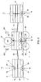
- Fig. 1 diagrammatically shows in partly sectional side elevation a travelling-tray oven 1 suitable for baking dish parts of like moldings in a number of linked baking molds 2.
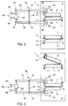
- the baking molds 2 are circulated in the direction indicated by the arrow P, the baking molds 2 being successively passed through a closing station 3 (Fig. 2, right; Fig. 3), a baking zone 4, a removal station 5 (Fig. 2, left; Fig. 4), a filling station 6 and back again to the closing station 3.
- Each baking mold 2 is made up of a first mold section 7 and a second mold section 9 hingedly connected thereto along a hinge 8.
- the hinge 8 extends along one of the sides of the two mold sections 7, 9.
- the mold sections 7, 9 together form one or more baking forms B (Fig. 5).
- the first mold section 7 comprises runners 10 by which the baking mold 2 can be guided over a pair of track rails 11 extending through the oven.
- the second mold section 9 comprises on the side remote from the hinge 8 a guide roller 12 which can be guided by a guide rail 13 likewise extending through the oven.
- Each baking mold 2 further comprises a locking mechanism 14, of which one exemplary embodiment is depicted in Fig. 6.
- the first mold section 7 comprises on the side remote from the hinge 8 a first flange 15 and the second mold section 9 comprises on the side remote from the hinge 8 a second flange 16.
- the first flange 15 and the second flange 16 are disposed against each other.
- a locking pin 17 which can only rotate about its longitudinal axis L.
- the locking pin comprises a cross 18 consisting of two legs 19 and 20 extending perpendicularly to the longitudinal axis L and to each other.
- the locking pin 17, at a distance a from the top 21 of the first flange 15, comprises a locking face 22 extending parallel to the longitudinal axis L of the locking pin.
- the locking face 22 has a thickness which is less than the thickness of the locking pin 17, and has two opposite sides 23 projecting outside the locking pin 17.
- the second flange 16 comprises a through opening 24 whose cross section corresponds substantially with the cross section of the locking pin 17, taken through the locking face 22 and at right angles to the longitudinal axis L.
- the upper end of the locking pin 17 is receivable in the opening 24, the locking face extending outside the side of the second flange 16 remote from the first flange 15.
- the lower end 25 of the locking face 22 is then substantially level with the top surface 27 of the second flange 16.
- the locking pin 17 By rotation of the locking pin 17, it can be brought into a first position wherein the locking face 22, in the closed position of the mold 2, extends entirely above the opening 24 within the contours thereof, and a second position wherein the locking face 22 extends substantially outside the contours of the opening 24.
- the first position is the unlocking position because the second mold section 9 can then be moved relative to the first mold section 7.
- the second position is the locking position since then the two mold sections are locked relative to each other.
- the baking molds are linked, for instance by a driving chain 26.
- the driving chain 26 is driven in a generally known manner by a driving mechanism, not shown in the drawing, whereby the baking molds 2 are pulled through the oven 1.
- a baking mold 2 is supplied in opened condition to the filling station 6, where an amount of dough is placed in the baking mold.
- the guide roller 12 then runs through a first part 13' of the guide rail 13, arranged at a relatively large distance from the track rails 11. Thereafter the baking mold is passed to the closing station 3, with the second mold section 9 being pivoted in the direction of the first mold section 7.
- the first part 13' of the guide rail 13 is bent between the filling station 6 and the closing station 3 in the direction of the track rails 11, and the guide rail 13 extends from the closing station parallel to the track rails 11 through the baking zone 4. In the closing station 3 the baking mold is pressed shut and locked.
- the closing actuator 30 Arranged in the closing station 3 is a closing actuator 30 by which the mold sections 7 and 9, active controlled, can be moved relative to each other in the closing direction.
- the closing actuator 30 comprises an upper lever 32 rotatable about a first point of rotation 31 and a lower lever 34 rotatable about a second point of rotation 33.
- the points of rotation 31, 33 are interconnected by a rod 35 which is connected to the oven 1.
- the levers 32, 34 extend substantially parallel to each other, transversely to the direction of travel of the baking molds 2.
- Mounted on the upper lever at one end 36 thereof is a pressure roller 37, which is bearing-mounted on a pin extending substantially parallel to the upper lever 32.
- the pressure roller 37 and the support rollers 39 lie substantially in one plane, while the pressure roller 37 is arranged halfway between the two support rollers 39, the support rollers 39 extend substantially under the track rails 11 and the pressure roller 37 is situated substantially at a distance above the track rails 11.
- the ends 40, 41 of the upper lever 32 and the lower lever 34, respectively, located on the side of the points of rotation 31, 33 remote from the rollers 37, 39, are connected with each other by a force transmission device 42.
- the force transmission device 42 By the use of the force transmission device 42, the pressure roller 37 and the support rollers 39 can be moved relative to each other in a direction approximately at right angles to the axes of rotation of the rollers, between a first, open position (indicated in the drawing by dotted lines) and a second, closed position (shown in solid lines in the drawing).
- the levers are brought into the open position, prior to an opened baking mold being fed into the closing station 3.
- a baking mold 2 is placed between the pressure rollers 37 and the support rollers 39, and the levers 32, 34 are moved into the closed position by energization of the force transmission device 42.
- the pressure roller 37 is thereby moved against the upper side of the second mold section 9 and the support rollers 39 are moved against the lower side of the first mold section 7.
- the first mold section is then preferably lifted to some extent, whereby the runners 10 on the side of the actuator 30 are taken off the track rail 11.
- the pressure roller 37 is moved further down in the direction of the support rollers 39 with a dosed force, whereby the mold sections are fully pressed against each other.
- the locking pin 17 is rotated into the second position (Fig. 6), so that the baking mold 2 is locked.
- a fixed stop 43 is placed in the path of travel of the cross 18 in the closing station 3 (Fig. 6).
- the cross 18 is moved by the first leg 20 thereof against the stop 43.
- the stop 43 is fixedly arranged at least in the direction of travel P of the baking mold 2
- the locking pin 17 will be rotated upon movement of the baking mold, in such a manner that the first leg 20 will extend parallel to the path of travel of the baking mold 2 and the second leg 19 perpendicularly thereto. The locking pin 17 is thus brought into the locking position.
- the levers 32, 34 are moved back into the open position, whereby the pressure roller 37 and the support rollers 39 are moved away from the baking molds, the runners 10 are placed back onto the track rail 11 and the baking mold 2 can be guided through the baking zone 4 in closed and locked condition.
- the baking mold 2 After baking the products in the baking zone 4, the baking mold 2 is passed into the removal station 5, where the baking mold 2 is opened and the baked products are removed from the baking forms. Then the baking mold in open condition is passed further to the filling station 6, and a next baking cycle is commenced.
- an opening actuator 50 is arranged in the removal station, by which the mold sections 7 and 9, actively controlled, can be moved relative to each other in the closing and opening direction.
- the opening actuator 50 is comparable with the closing actuator 30 but is turned upside down with respect to it.
- an upper lever 51 comprises the two support rollers 52
- a lower lever 53 comprises the pressure roller 54.
- the levers 51, 53 Prior to the baking mold being fed into the removal station 5, the levers 51, 53 are brought into the opened position by means of a force transmission device 55 arranged between the ends of the levers 51, 53 remote from the rollers 52, 54.
- the baking mold is then moved freely between the rollers 52, 54, that is, without the rollers 52, 54 applying pressure to the mold sections 7, 9.
- a second stop 56 Arranged in the path of travel of the cross 18 of the locking pin 17 is a second stop 56, not shown in the drawing, comparable to the first stop 43, which, upon forward movement of the baking mold 2, rotates the locking pin by a quarter turn, from the second position to the first position, in a manner comparable but opposite to the method of locking shown in Fig. 6.
- the pressure roller 52 and the support rollers 54 continue to abut against the relevant mold section 9, 7, so that the baking mold is maintained in the closed condition. Only after rotation of the locking pin 17 are the levers 51, 53, under active control, moved back gradually to the opened condition, so that the movement of the mold sections relative to each other and to the track rails 11 and the guide rail 13 occurs fluently and without extreme (shock) loads. This prevents the baking mold from springing open and hence damage to the baking mold, the oven and the products.
- a travelling-tray oven 1 has been described during normal use.
- the oven 1 and the baking molds 2 are to be heated up. It is then particularly advantageous when the baking molds, in a method according to the invention, are preheated in the oven prior to baking, whereby the baking molds are closed and locked only once and are then circulated through the oven a number of times in closed condition.
- the different mold sections, the oven and the different operating means such as the actuators are subject to lesser loads, and which vary to a lesser extent, so that their life is considerably prolonged.
- the guide rail 13 between the removal station 5 and the closing station 3 comprises a first section 13', constituting an outside bend, and a second section 13'', constituting an inside bend, while the actuators 30, 50 and the stops 43, 56 are movable out of the path of travel of the baking mold 2.
- the oven 1 is used as follows.
- the baking molds 2 are passed into the closing station 3 one by one, the baking molds 2 being closed and locked in the conventional manner.
- the opening actuator 50 is brought into the opened position and fixed therein, while the stop 56 in the removal station 5 is pulled away out of the path of travel of the locking pins 17.
- the guide rail in the removal station 5 includes a switch 57 which can connect the section of the guide rail 13 that extends through the baking zone 4 of the oven with the outside bend 13' or with the inside bend 13'', as desired. During heat-up, the switch 57 is set in such a manner that the guide roller 12 is passed through the inside bend 13''.
- the closing actuator 30 is also brought into the opened position and maintained therein, and the associated stop 43 is brought outside the path of movement of the locking pins 17.
- the guide rail 13 likewise comprises a switch 58, between the section of the guide rail that extends through the baking zone 4, the outside bend 13' and the inside bend 13''. During heat-up of the baking molds 2, this switch 58, of course, is set in such a manner that the inside bend 13'' is connected to the remainder of the guide rail 13.
- the stops 43, 56 are moved back into the path of movement of the locking pans 17, the actuators 30, 50 are released again and the switches 57, 58 are set in such a manner that the outside bend 13' is connected to the guide rail 13, so that the baking molds 2 for baking products can be normally used.
- baking molds may also choose to circulate the baking molds through the oven a number of times during heating while in unlocked condition, analogously to the above-described manner. This provides advantages in particular in the case of baking molds where the difference between the closing tension in cold condition and the closing tension in hot condition (of use) is large.
- control means 60 are arranged for controlling the movements of the pressure roller 37, 52 relative to the support rollers 39, 54.
- These control means 60 comprise at least location detection means 61, position detection means 62, the force transmission device 42, 55 and force detection means 63.
- the force transmission device 42, 55 is preferably an air cylinder or like device, since it is has the advantage that a good buffer action is thereby obtained, while the force transmission device is simply, quickly and accurately operable and controllabe and relatively inexpensive.
- the location detection means 61 comprise a first signal generator 61' which supplies a signal at the time when a baking mold 2 is located in a desired position between the pressure roller 37, 52 and the support rollers 39, 54. As long as this signal is not produced, the force transmission device 42, 55 is controlled by the position detection means 62, in such a manner that the relevant levers 32, 34; 51, 53 are brought into the open position. As soon as the baking mold 2 has been brought into the desired position and the first signal generator 61' has produced the desired signal, the force transmission device 42, 55 is actuated and the relevant levers 32, 34; 51, 53 are brought into the closed condition.
- the force transmission detection means 63 are arranged so that they measure the force which is exerted by the pressure roller 37, 52 and the support rollers 39, 54 on the mold sections 9, 7. By means of the force detection means 63 a closing force can be set which must be achieved for closing the baking mold. When this closing force is achieved, the baking mold 2 is locked or unlocked.
- a maximum closing force can be set. If this maximum closing force is exceeded, the force detection means 63 produce an emergency signal, so that the stop 43 arranged at the relevant closing actuator 30 is moved out of the path of movement of the locking pin 17 of the relevant baking mold, for instance by pulling the stop 43 away in downward direction. This prevents the locking pin, the baking mold and/or the stop from being damaged if the baking mold cannot be closed with a force less than the set maximum closing force. This may for instance occur when soiling has arisen between the land areas of the baking mold or in case the baking mold has not been emptied (completely) in the removal station but thereafter has nevertheless been provided with a new amount of dough.
- a second signal generator 61'' is positioned on the side of the actuator 30, 50 which is the rear side when viewed in the direction of supply of the baking molds.
- a second signal generator 61'' is positioned on the side of the actuator 30, 50 which is the rear side when viewed in the direction of supply of the baking molds.
- a second signal is produced, so that the force transmission device 42, 55 is actuated and the levers 32, 34; 51, 53 are driven into the open position.
- this movement towards the opened position can be performed relatively quickly and independently; at the opening actuator 50 this movement is controlled inter alia by the force detection means 63 and the force transmission device 55.
- the levers 32, 34, 51, 53 largely extend outside the casing of the oven 1, so that cooling of these parts, and in particular of the energization device and of the different points of rotation, can at least substantially be omitted.
- the pressure roller 37, 52 and the support rollers 39, 54 of the actuators 30, 50 are preferably air or water-cooled, so that a long life of the different bearings of the rollers is enhanced.
- the actuators 30, 50 each constitute a closed-force system, which means that the actuators 30, 50 transmit no or only small forces to the different parts of the oven 1.
- the forces are at least substantially absorbed by the connecting rod 35 between the points of rotation 31, 33 of the levers 32, 34; 51. 53, by the force transmission device 42, 55 and by the baking mold 2.
- no special provisions need to be made on the oven 1, such as for instance stiffening provisions for the casing, the track rails 11 or the guide rail 13, 13', or 13'' .
- An actuator 30, 50 according to the invention moreover substantially absorbs the forces to be transmitted to the baking mold for closing and opening it, so that loads on the runners 10 and the guide roller 12 are kept to a minimum and hence the life of the runners 10 and of the guide roller 12 is prolonged.
- the bearings for the runners 10 and the guide roller 12 can be of simple and light design.
- baking molds of always the same kind are shown. In an oven according to the invention, however, it is possible to simultaneously pass baking molds of different kinds through the oven. Differences in the thicknesses of molds among themselves, any deviations in size and differences in the desired closing force can be simply accommodated with the actuators 30, 50 according to the invention by adjusting the settings and in that use is made of the location detection means 61, the position detection means 62, the force detection means 63 and the force transmission means 42, 55. It is here preferred that means are arranged which can recognize a baking mold presented at an actuator 30, 50 by kind. On the basis of the kind of baking mold 2 and the signals produced by the different detection means 61, 62, 63, an actuator signal suitable for the energization of the actuator 30, 50 can be supplied to the force transmission device 42, 55.
- the stops 43, 56 for operating the locking pins 17 can be fixedly connected with an arm of the relevant control 30, 50 and it may be possible for the actuators 30, 50 to be pulled clear of the path of movement of the baking molds 2, in such a manner that thus the relevant stop 43, 56 is also moved out of the path of movement of the locking pin.
- the force transmission device can connect the levers of an actuator at positions located between the points of rotation and the pressure roller and support rollers, respectively.
- the pressure roller and the support rollers of an actuator can be moved relative to each other in a different manner than by means of levers, for instance by means of pistons, and a different number of rollers can be used.
- the baking molds can be provided with all sorts of different kinds of locking means and with mold sections moving relative to each other in different ways, and the baking molds can be circulated in different ways through different kinds of ovens, for instance through a circular oven.
Landscapes
- Life Sciences & Earth Sciences (AREA)
- Engineering & Computer Science (AREA)
- Food Science & Technology (AREA)
- Baking, Grill, Roasting (AREA)
- Meat, Egg Or Seafood Products (AREA)
- Cookers (AREA)
- Moulding By Coating Moulds (AREA)
- Pinball Game Machines (AREA)
Claims (23)
- Verfahren zur Herstellung von Produkten in einer Reihe von Backformen, die einen Ofen durchlaufen, wobei die Backformen mindestens zwei relativ zueinander bewegliche Backabschnitte aufweisen, wobei die Backform in einem Backzyklus nacheinander geöffnet, gefüllt, in einer Schließstation geschlossen und verriegelt wird, entlang einer Anzahl von durch den Ofen verlaufenden Führungen geführt und in einer Entnahmestation geöffnet und geleert wird,
dadurch gekennzeichnet, daß mindestens ein Teil der Bewegungen der Backabschnitte relativ zueinander durch Betätigungseinrichtungen gesteuert werden, die relativ zueinander unter aktiver Steuerung bewegbar sind und die zum Zwecke der Bewegungssteuerung der Backabschnitte relativ zueinander eine in Schließrichtung gerichtete Kraft auf die Backabschnitte aufbringen. - Verfahren nach Anspruch 1, dadurch gekennzeichnet, daß die Betätigungseinrichtungen eine Schließdruckeinrichtung und eine Schließabstützeinrichtung aufweisen, die relativ zueinander bewegt werden können und vor dem Einbringen der Backform in die Schließstation relativ zueinander in eine erste Position bewegt werden und die Backform ohne Aufbringung einer Schließkraft auf die Backform zwischen sie geschoben wird, daß danach die Schließdruckeinrichtung und die Schließabstützeinrichtung relativ zueinander in eine zweite Position bewegt werden, wobei die Schließdruckeinrichtung einen solchen Schließdruck auf die Backform ausübt, daß die Backform geschlossen und danach verriegelt wird.
- Verfahren nach Anspruch 2, dadurch gekennzeichnet, daß nach Verriegelung der Backform und vor Führung derselben aus der Schließstation die Schließdruckeinrichtung und die Schließabstützeinrichtung in Richtung der ersten Position zurückbewegt werden.
- Verfahren nach einem der vorhergehenden Ansprüche, dadurch gekennzeichnet, daß die Betätigungseinrichtungen eine Entnahmedruckeinrichtung und eine Entnahmeabstützeinrichtung aufweisen, die vor Einführung der Backform in die Entnahmestation relativ zueinander in eine erste Position bewegt werden, wobei die Backform zwischen sie geschoben wird, ohne daß die Entnahmeeinrichtung eine Druckkraft auf die Backform aufbringt, daß danach die Entnahmedruckeinrichtung und die Entnahmeabstützeinrichtung relativ zueinander in eine zweite Position bewegt werden, wobei die Entnahmedruckeinrichtung eine Druckkraft auf die Backform in Schließrichtung aufbringt, daß die Backform entriegelt wird und danach während des Öffnens der Backform die Entnahmedruckeinrichtung und die Entnahmeabstützeinrichtung relativ zueinander in Richtung der zweiten Position zurückbewegt werden, wobei die Entnahmedruckeinrichtung eine Druckkraft auf die Backform in Schließrichtung ausübt, welche geringer ist als die Kraft, die auf die Backabschnitte in der der Schließrichtung entgegengesetzten Richtung aufgebracht wird.
- Verfahren nach einem der vorhergehenden Ansprüche, dadurch gekennzeichnet, daß während der Bewegung der Backabschnitte relativ zueinander die Backform zumindest teilweise aus der Führung genommen wird, wobei die Backform so gehalten wird, daß die durch die Betätigungseinrichtungen erzeugte Kraft zumindest im wesentlichen von den Betätigungseinrichtungen aufgenommen wird.
- Verfahren nach einem der Ansprüche 2 - 5, dadurch gekennzeichnet, daß die Druckeinrichtung relativ zu der Abstützeinrichtung in einer in wesentlichen rechtwinklig zu den Führungen verlaufenden Richtung bewegt wird.
- Verfahren nach einem der vorhergehenden Ansprüche, dadurch gekennzeichnet, daß die Backformen vor deren Einsatz zum Backen der Formlinge im Ofen vorgewärmt werden, wobei die Backformen geschlossen und dann mehrmals nacheinander durch den Ofen geführt werden, ohne daß die Backformen geöffnet werden.
- Verfahren nach Anspruch 7, dadurch gekennzeichnet, daß während des Vorwärmens der Backformen die Betätigungseinrichtungen aus der Bahn der Backformen herausbewegt werden.
- Ofen mit einer Reihe von Backformen, die nacheinander durch den Ofen geführt werden, wobei der Ofen mindestens eine Schließstation, eine Entnahmestation und eine Backzone aufweist und jede Backform einen ersten und einen zweiten Formabschnitt hat, wobei der erste Formabschnitt eine Führungseinrichtung aufweist, mittels derer die Backform entlang einer Anzahl von durch den Ofen verlaufenden Führungen geführt werden kann, weiterhin die Betätigungseinrichtungen zum Drücken der Formabschnitte in Schließrichtung sowie Verriegelungseinrichtungen und Verriegelungsbetätigungseinrichtungen zum Verriegeln und Entriegeln der Backform,
dadurch gekennzeichnet, daß die Betätigungsvorrichtungen ein erstes Betätigungsglied mit Schließdruckeinrichtung und Schließabstützeinrichtung aufweisen, die relativ zueinander bewegt werden können zwischen einer ersten Position, in der die Backform im wesentlichen frei zwischen der und durch die Schließdruckeinrichtung und Schließabstützeinrichtung bewegt werden kann, und einer zweiten Position, in der die Backform in geschlossenem Zustand vor Verriegelung derselben gleichzeitig mit der Schließdruckeinrichtung und der Schließabstützeinrichtung unter Aufbringung einer Schließspannung in Kontakt gebracht wird oder gebracht werden kann. - Ofen nach Anspruch 9, dadurch gekennzeichnet, daß die Betätigungseinrichtungen ein zweites Betätigungsglied mit Entnahmedruckeinrichtung und Entnahmeabstützeinrichtung aufweisen, die relativ zueinander bewegt werden können zwischen einer ersten Position, in der die Backform im wesentlichen frei zwischen der und durch die Entnahmedruckeinrichtung und Entnahmeabstützeinrichtung bewegt werden kann, und einer zweiten Position, in der die Backform in geschlossenem Zustand vor der Entriegelung gleichzeitig mit der Entnahmedruckvorrichtung und der Entnahmeabstützvorrichtung, die in einer Schließrichtung vorgespannt sind, in Kontakt gebracht werden kann, wobei eine Einrichtung für das gesteuerte Öffnen der Backform nach der Entriegelung vorgesehen ist.
- Ofen nach Anspruch 10, dadurch gekennzeichnet, daß die Entnahmeabstützeinrichtung und die Entnahmedruckeinrichtung eine Anzahl Rollen aufweisen, während in der zweiten Position der Entnahmedruckeinrichtung und der Entnahmeabstützeinrichtung mindestens eine erste Rolle eine Lauffläche hat, die so an dem ersten Formabschnitt anliegt und mindestens eine zweite Rolle eine Lauffläche, die so an dem zweiten Formabschnitt anliegt, daß die für die Anpressung der Backform geeignete Kraft von den Rollen auf eine Bahn übertragen wird, auf der die Entriegelungseinrichtung angeordnet ist.
- Ofen nach einem der Ansprüche 9 - 11, dadurch gekennzeichnet, daß die Schließdruckeinrichtung und die Schließabstützeinrichtung eine Anzahl von Rollen aufweisen, während in der zweiten Position der Schließdruckeinrichtung und der Schließabstützeinrichtung mindestens eine erste Rolle eine Lauffläche aufweist, die so an dem ersten Formabschnitt anliegt, und mindestens eine zweite Rolle eine Lauffläche, die so an dem zweiten Formabschnitt anliegt, daß die zum Schließen der Backform geeignete Kraft auf eine Bahn übertragen wird, auf der die Verriegelungsbetätigungseinrichtung angeordnet ist.
- Ofen nach Anspruch 11 oder 12, dadurch gekennzeichnet, daß jede erste Rolle an einem ersten Hebel befestigt ist und jede zweite Rolle an einem zweiten Hebel, wobei mindestens einer der Hebel so angeordnet ist, daß er sich relativ zu dem anderen Hebel bewegt, während zwischen den Hebeln eine Kraftübertragungsvorrichtung zum Bewegen von mindestens einem der Hebel so angeordnet ist, daß der Abstand zwischen der entsprechenden ersten und zweiten Rolle einstellbar ist.
- Ofen nach Anspruch 13, dadurch gekennzeichnet, daß die von der Kraftübertragungsvorrichtung zu erzeugende Kraft einstellbar ist.
- Ofen nach Anspruch 14, dadurch gekennzeichnet, daß die Kraftübertragungsvorrichtung einen Luftzylinder aufweist.
- Ofen nach einem der Ansprüche 10 - 15, dadurch gekennzeichnet, daß jedes Betätigungsglied eine Einheit mit geschlossenem Kräfteverlauf bildet.
- Ofen nach einem der Ansprüche 10 - 16, dadurch gekennzeichnet, daß die Betätigungsglieder teilweise aus einem den Ofen umgebenden Gehäuse hervorstehen.
- Ofen nach einem der Ansprüche 11 - 17, dadurch gekennzeichnet, daß die Rollen gekühlte Lager aufweisen.
- Ofen nach einem der Ansprüche 11 - 18, dadurch gekennzeichnet, daß mindestens die Betätigungsglieder und die Verriegelungsbetätigungsvorrichtung aus der Laufbahn der Backform bewegt werden können, wobei die Anordnung so erfolgt, daß die Backformen in geschlossenem Zustand mehr als einmal den Ofen durchlaufen können.
- Ofen nach einem der Ansprüche 11 - 19, bei dem der Ofen eine Führungsschiene aufweist, die mindestens die Schließstation, die Entnahmestation und die Backzone durchläuft, während jeder zweite Backformenabschnitt eine Führungseinrichtung hat, die mit der Führungsschiene zusammenwirkt, dadurch gekennzeichnet, daß mindestens der Teil der Führungsschiene, der sich in die Entnahmestation erstreckt, außer Kontakt mit der Führungseinrichtung gebracht werden kann.
- Ofen nach Anspruch 20, dadurch gekennzeichnet, daß der Teil der Führungsschiene, der sich in die Schließstation erstreckt, unabhängig von dem Teil der Führungsschiene, der sich in die Entnahmestation erstreckt, außer Kontakt mit der Führungseinrichtung gebracht werden kann.
- Ofen nach Anspruch 20 oder 21, dadurch gekennzeichnet, daß die Führungsschiene Schalter aufweist, mittels derer die entsprechenden Teile der Führungsschiene außer Kontakt mit der Führungseinrichtung gebracht werden.
- Betätigungsglied zur Verwendung für die Steuerung der Bewegungen der Formabschnitte relativ zueinander in einem Durchlaufofen mit mindestens einer Druckrolle, mindestens einer Abstützrolle und einer Steuereinrichtung, wobei die Abstützrolle und die Druckrolle übereinander angeordnet sind und ungefähr parallele Drehachsen aufweisen und relativ zueinander in einer ungefähr rechtwinkligen Richtung zu den Drehachsen bewegt werden können, während die Steuereinrichtung mindestens eine Ortserfassungseinrichtung, eine Positionserfassungseinrichtung, eine Kraftübertragungseinrichtung und eine Krafterfassungseinrichtung aufweist, wobei die Ortserfassungseinrichtung so angeordnet ist, daß die Position einer Backform relativ zum Betätigungsglied bestimmt werden kann, die Positionserfassungseinrichtung so angeordnet ist, daß die Position der Druckrolle relativ zu der Abstützrolle bestimmt werden kann, die Kraftübertragungseinrichtung zur gesteuerten Bewegung der Druckrolle und der Abstützrolle relativ zueinander angeordnet ist und die Krafterfassungseinrichtung so angeordnet ist, daß die Größe der vom Betätigungsglied auf die Backform übertragenen Kräfte bestimmt werden kann.
Applications Claiming Priority (3)
| Application Number | Priority Date | Filing Date | Title |
|---|---|---|---|
| NL9400619 | 1994-04-18 | ||
| NL9400619A NL9400619A (nl) | 1994-04-18 | 1994-04-18 | Werkwijze en inrichting voor het openen en sluiten van bakmatrijzen voor gebruik in een doorloopoven. |
| PCT/NL1995/000139 WO1995028086A1 (en) | 1994-04-18 | 1995-04-18 | Method and apparatus for opening and closing baking molds for use in a continuous oven |
Publications (2)
| Publication Number | Publication Date |
|---|---|
| EP0706324A1 EP0706324A1 (de) | 1996-04-17 |
| EP0706324B1 true EP0706324B1 (de) | 1999-07-07 |
Family
ID=19864084
Family Applications (1)
| Application Number | Title | Priority Date | Filing Date |
|---|---|---|---|
| EP95914580A Expired - Lifetime EP0706324B1 (de) | 1994-04-18 | 1995-04-18 | Verfahren und vorrichtung zum öffnen und schliessen von backzangen in einem durchlaufofen |
Country Status (7)
| Country | Link |
|---|---|
| US (1) | US5786013A (de) |
| EP (1) | EP0706324B1 (de) |
| AT (1) | ATE181796T1 (de) |
| AU (1) | AU2149795A (de) |
| DE (1) | DE69510629T2 (de) |
| NL (1) | NL9400619A (de) |
| WO (1) | WO1995028086A1 (de) |
Families Citing this family (5)
| Publication number | Priority date | Publication date | Assignee | Title |
|---|---|---|---|---|
| US6258395B1 (en) * | 1997-10-15 | 2001-07-10 | Smtm Group, Llc | Method for pressure baking |
| US6156364A (en) * | 2000-03-09 | 2000-12-05 | Kraft Foods, Inc. | Molded pizza crust |
| US6858241B1 (en) | 2001-07-25 | 2005-02-22 | Smtm Group, Llc. | Farinaceous surface product that is toaster reheatable and method |
| AT513949B1 (de) * | 2013-01-18 | 2015-10-15 | Haas Food Equipment Gmbh | Backvorrichtung |
| CN110250230B (zh) * | 2019-07-11 | 2024-03-08 | 珠海格力智能装备有限公司 | 蛋卷成型设备 |
Family Cites Families (4)
| Publication number | Priority date | Publication date | Assignee | Title |
|---|---|---|---|---|
| GB2135178B (en) * | 1983-02-18 | 1986-04-09 | Allied Bakeries Ltd | Baking apparatus for use in making waffles |
| AT391589B (de) * | 1988-10-20 | 1990-10-25 | Haas Franz Waffelmasch | Betaetigungsvorrichtung fuer den verschluss der backzangen eines waffelbackofens zur erzeugung von verrottbaren, vorzugsweise essbaren waffeln |
| US5016528A (en) * | 1990-06-20 | 1991-05-21 | Chen Tsai An | Baking apparatus |
| DE4140138A1 (de) * | 1991-12-05 | 1993-06-09 | Rapido Waagen- Und Maschinenfabrik Gmbh, O-8122 Radebeul, De | Verfahren und einrichtung zur anwesenheitserkennung von waffelblaettern |
-
1994
- 1994-04-18 NL NL9400619A patent/NL9400619A/nl not_active Application Discontinuation
-
1995
- 1995-04-18 WO PCT/NL1995/000139 patent/WO1995028086A1/en not_active Ceased
- 1995-04-18 DE DE69510629T patent/DE69510629T2/de not_active Expired - Fee Related
- 1995-04-18 EP EP95914580A patent/EP0706324B1/de not_active Expired - Lifetime
- 1995-04-18 US US08/569,110 patent/US5786013A/en not_active Expired - Fee Related
- 1995-04-18 AU AU21497/95A patent/AU2149795A/en not_active Abandoned
- 1995-04-18 AT AT95914580T patent/ATE181796T1/de not_active IP Right Cessation
Also Published As
| Publication number | Publication date |
|---|---|
| EP0706324A1 (de) | 1996-04-17 |
| US5786013A (en) | 1998-07-28 |
| DE69510629D1 (de) | 1999-08-12 |
| AU2149795A (en) | 1995-11-10 |
| NL9400619A (nl) | 1995-12-01 |
| DE69510629T2 (de) | 2000-04-06 |
| WO1995028086A1 (en) | 1995-10-26 |
| ATE181796T1 (de) | 1999-07-15 |
Similar Documents
| Publication | Publication Date | Title |
|---|---|---|
| US4953453A (en) | Apparatus for operating locks of baking tongs for producing rottable, preferably edible wafers from wafer dough in a wafer baking oven or an automatic wafer baking machine | |
| US4966071A (en) | Bread molders | |
| US5786013A (en) | Method and apparatus for opening and closing baking molds for use in a continuous oven | |
| US5222587A (en) | Device for moving parts from one station to another along a line for processing them | |
| US4719849A (en) | Food product cooker | |
| JPH03117873A (ja) | 板形冷凍機用積載装置 | |
| NL8103603A (nl) | Kunststof-spuitgietmachine met een het vormbereik afdekkende beschermafdekking. | |
| US1923836A (en) | Loading machine | |
| EP0377491B1 (de) | Verfahren und Ausrüstung für die Be- und Entladung eines Fahrzeuges | |
| US2222732A (en) | Press | |
| US3841186A (en) | Machine for cutting meat joints, specially breasts of pork | |
| CN106586109B (zh) | 一种针剂自动给料机 | |
| GB2111010A (en) | Buffer chain conveyor | |
| CA2160479A1 (en) | Device for releasing a product from a continuously circulating belt | |
| US2032446A (en) | Automatic charging device for tunnel ovens | |
| JPH02276706A (ja) | 懸架搬送装置 | |
| US5107976A (en) | Transport device | |
| NO153176B (no) | Analogifremgangsmaate ved fremstilling av den terapeutisk virksomme cis-isomer av morfolinderivater | |
| US3548744A (en) | Press box with improved door arrangement | |
| US3018872A (en) | Tray for baking oven | |
| US1876252A (en) | Device for handling molds | |
| JPS5934338B2 (ja) | 塊成型に食品材料を詰める方法および機構 | |
| JPS5915298B2 (ja) | 成型機械 | |
| US2883032A (en) | Article transfer apparatus | |
| CN220642063U (zh) | 一种电缆绕线器底部自动开合装置 |
Legal Events
| Date | Code | Title | Description |
|---|---|---|---|
| PUAI | Public reference made under article 153(3) epc to a published international application that has entered the european phase |
Free format text: ORIGINAL CODE: 0009012 |
|
| AK | Designated contracting states |
Kind code of ref document: A1 Designated state(s): AT BE CH DE DK FR GB IT LI NL SE |
|
| 17P | Request for examination filed |
Effective date: 19960426 |
|
| GRAG | Despatch of communication of intention to grant |
Free format text: ORIGINAL CODE: EPIDOS AGRA |
|
| 17Q | First examination report despatched |
Effective date: 19980730 |
|
| GRAG | Despatch of communication of intention to grant |
Free format text: ORIGINAL CODE: EPIDOS AGRA |
|
| GRAH | Despatch of communication of intention to grant a patent |
Free format text: ORIGINAL CODE: EPIDOS IGRA |
|
| GRAH | Despatch of communication of intention to grant a patent |
Free format text: ORIGINAL CODE: EPIDOS IGRA |
|
| GRAA | (expected) grant |
Free format text: ORIGINAL CODE: 0009210 |
|
| AK | Designated contracting states |
Kind code of ref document: B1 Designated state(s): AT BE CH DE DK FR GB IT LI NL SE |
|
| PG25 | Lapsed in a contracting state [announced via postgrant information from national office to epo] |
Ref country code: SE Free format text: THE PATENT HAS BEEN ANNULLED BY A DECISION OF A NATIONAL AUTHORITY Effective date: 19990707 Ref country code: LI Free format text: LAPSE BECAUSE OF FAILURE TO SUBMIT A TRANSLATION OF THE DESCRIPTION OR TO PAY THE FEE WITHIN THE PRESCRIBED TIME-LIMIT Effective date: 19990707 Ref country code: IT Free format text: LAPSE BECAUSE OF FAILURE TO SUBMIT A TRANSLATION OF THE DESCRIPTION OR TO PAY THE FEE WITHIN THE PRE;WARNING: LAPSES OF ITALIAN PATENTS WITH EFFECTIVE DATE BEFORE 2007 MAY HAVE OCCURRED AT ANY TIME BEFORE 2007. THE CORRECT EFFECTIVE DATE MAY BE DIFFERENT FROM THE ONE RECORDED.SCRIBED TIME-LIMIT Effective date: 19990707 Ref country code: FR Free format text: LAPSE BECAUSE OF FAILURE TO SUBMIT A TRANSLATION OF THE DESCRIPTION OR TO PAY THE FEE WITHIN THE PRESCRIBED TIME-LIMIT Effective date: 19990707 Ref country code: CH Free format text: LAPSE BECAUSE OF FAILURE TO SUBMIT A TRANSLATION OF THE DESCRIPTION OR TO PAY THE FEE WITHIN THE PRESCRIBED TIME-LIMIT Effective date: 19990707 Ref country code: AT Free format text: LAPSE BECAUSE OF FAILURE TO SUBMIT A TRANSLATION OF THE DESCRIPTION OR TO PAY THE FEE WITHIN THE PRESCRIBED TIME-LIMIT Effective date: 19990707 |
|
| REF | Corresponds to: |
Ref document number: 181796 Country of ref document: AT Date of ref document: 19990715 Kind code of ref document: T |
|
| REG | Reference to a national code |
Ref country code: CH Ref legal event code: EP |
|
| REF | Corresponds to: |
Ref document number: 69510629 Country of ref document: DE Date of ref document: 19990812 |
|
| PG25 | Lapsed in a contracting state [announced via postgrant information from national office to epo] |
Ref country code: DK Free format text: LAPSE BECAUSE OF FAILURE TO SUBMIT A TRANSLATION OF THE DESCRIPTION OR TO PAY THE FEE WITHIN THE PRESCRIBED TIME-LIMIT Effective date: 19991007 |
|
| EN | Fr: translation not filed | ||
| REG | Reference to a national code |
Ref country code: CH Ref legal event code: PL |
|
| PLBE | No opposition filed within time limit |
Free format text: ORIGINAL CODE: 0009261 |
|
| STAA | Information on the status of an ep patent application or granted ep patent |
Free format text: STATUS: NO OPPOSITION FILED WITHIN TIME LIMIT |
|
| 26N | No opposition filed | ||
| REG | Reference to a national code |
Ref country code: GB Ref legal event code: IF02 |
|
| REG | Reference to a national code |
Ref country code: GB Ref legal event code: 732E |
|
| NLS | Nl: assignments of ep-patents |
Owner name: PAPERFOAM B.V. |
|
| PGFP | Annual fee paid to national office [announced via postgrant information from national office to epo] |
Ref country code: BE Payment date: 20080520 Year of fee payment: 14 |
|
| PGFP | Annual fee paid to national office [announced via postgrant information from national office to epo] |
Ref country code: NL Payment date: 20080415 Year of fee payment: 14 Ref country code: DE Payment date: 20080626 Year of fee payment: 14 |
|
| PGFP | Annual fee paid to national office [announced via postgrant information from national office to epo] |
Ref country code: GB Payment date: 20080404 Year of fee payment: 14 |
|
| BERE | Be: lapsed |
Owner name: *PAPERFOAM B.V. Effective date: 20090430 |
|
| GBPC | Gb: european patent ceased through non-payment of renewal fee |
Effective date: 20090418 |
|
| NLV4 | Nl: lapsed or anulled due to non-payment of the annual fee |
Effective date: 20091101 |
|
| PG25 | Lapsed in a contracting state [announced via postgrant information from national office to epo] |
Ref country code: DE Free format text: LAPSE BECAUSE OF NON-PAYMENT OF DUE FEES Effective date: 20091103 |
|
| PG25 | Lapsed in a contracting state [announced via postgrant information from national office to epo] |
Ref country code: NL Free format text: LAPSE BECAUSE OF NON-PAYMENT OF DUE FEES Effective date: 20091101 |
|
| PG25 | Lapsed in a contracting state [announced via postgrant information from national office to epo] |
Ref country code: GB Free format text: LAPSE BECAUSE OF NON-PAYMENT OF DUE FEES Effective date: 20090418 |
|
| PG25 | Lapsed in a contracting state [announced via postgrant information from national office to epo] |
Ref country code: BE Free format text: LAPSE BECAUSE OF NON-PAYMENT OF DUE FEES Effective date: 20090430 |