EP0706491B1 - Vorrichtung zur pendelnden speicherung - Google Patents
Vorrichtung zur pendelnden speicherung Download PDFInfo
- Publication number
- EP0706491B1 EP0706491B1 EP95915731A EP95915731A EP0706491B1 EP 0706491 B1 EP0706491 B1 EP 0706491B1 EP 95915731 A EP95915731 A EP 95915731A EP 95915731 A EP95915731 A EP 95915731A EP 0706491 B1 EP0706491 B1 EP 0706491B1
- Authority
- EP
- European Patent Office
- Prior art keywords
- installation according
- shelves
- shelf
- coupling members
- longitudinal coupling
- Prior art date
- Legal status (The legal status is an assumption and is not a legal conclusion. Google has not performed a legal analysis and makes no representation as to the accuracy of the status listed.)
- Expired - Lifetime
Links
Images





Classifications
-
- B—PERFORMING OPERATIONS; TRANSPORTING
- B65—CONVEYING; PACKING; STORING; HANDLING THIN OR FILAMENTARY MATERIAL
- B65G—TRANSPORT OR STORAGE DEVICES, e.g. CONVEYORS FOR LOADING OR TIPPING, SHOP CONVEYOR SYSTEMS OR PNEUMATIC TUBE CONVEYORS
- B65G1/00—Storing articles, individually or in orderly arrangement, in warehouses or magazines
- B65G1/02—Storage devices
- B65G1/04—Storage devices mechanical
- B65G1/12—Storage devices mechanical with separate article supports or holders movable in a closed circuit to facilitate insertion or removal of articles the articles being books, documents, forms or the like
- B65G1/127—Storage devices mechanical with separate article supports or holders movable in a closed circuit to facilitate insertion or removal of articles the articles being books, documents, forms or the like the circuit being confined in a vertical plane
-
- B—PERFORMING OPERATIONS; TRANSPORTING
- B65—CONVEYING; PACKING; STORING; HANDLING THIN OR FILAMENTARY MATERIAL
- B65G—TRANSPORT OR STORAGE DEVICES, e.g. CONVEYORS FOR LOADING OR TIPPING, SHOP CONVEYOR SYSTEMS OR PNEUMATIC TUBE CONVEYORS
- B65G1/00—Storing articles, individually or in orderly arrangement, in warehouses or magazines
- B65G1/02—Storage devices
- B65G1/04—Storage devices mechanical
- B65G1/0457—Storage devices mechanical with suspended load carriers
-
- B—PERFORMING OPERATIONS; TRANSPORTING
- B65—CONVEYING; PACKING; STORING; HANDLING THIN OR FILAMENTARY MATERIAL
- B65G—TRANSPORT OR STORAGE DEVICES, e.g. CONVEYORS FOR LOADING OR TIPPING, SHOP CONVEYOR SYSTEMS OR PNEUMATIC TUBE CONVEYORS
- B65G47/00—Article or material-handling devices associated with conveyors; Methods employing such devices
- B65G47/34—Devices for discharging articles or materials from conveyor
- B65G47/46—Devices for discharging articles or materials from conveyor and distributing, e.g. automatically, to desired points
- B65G47/51—Devices for discharging articles or materials from conveyor and distributing, e.g. automatically, to desired points according to unprogrammed signals, e.g. influenced by supply situation at destination
- B65G47/5104—Devices for discharging articles or materials from conveyor and distributing, e.g. automatically, to desired points according to unprogrammed signals, e.g. influenced by supply situation at destination for articles
- B65G47/5109—Devices for discharging articles or materials from conveyor and distributing, e.g. automatically, to desired points according to unprogrammed signals, e.g. influenced by supply situation at destination for articles first In - First Out systems: FIFO
- B65G47/5113—Devices for discharging articles or materials from conveyor and distributing, e.g. automatically, to desired points according to unprogrammed signals, e.g. influenced by supply situation at destination for articles first In - First Out systems: FIFO using endless conveyors
- B65G47/5118—Devices for discharging articles or materials from conveyor and distributing, e.g. automatically, to desired points according to unprogrammed signals, e.g. influenced by supply situation at destination for articles first In - First Out systems: FIFO using endless conveyors with variable accumulation capacity
- B65G47/5122—Devices for discharging articles or materials from conveyor and distributing, e.g. automatically, to desired points according to unprogrammed signals, e.g. influenced by supply situation at destination for articles first In - First Out systems: FIFO using endless conveyors with variable accumulation capacity by displacement of the conveyor-guiding means, e.g. of the loose pulley-type
Definitions
- the present invention relates to a pendular storage installation for products, in particular food products and more particularly chocolate plates or the like, these products being placed on shelves arranged horizontally on gondolas hung horizontally with two chains mounted on a frame and running parallel between them on a closed circuit comprising a supply section going from a station for depositing the products on the shelves, to a station for receiving these products arranged to unload the shelves, and a return section in which the shelves are brought back empty of the receiving station at the deposition station, in which the frame is made up of at least one basic module made up of four vertical columns which are linked together in pairs by longitudinal lower and upper coupling elements respectively and by elements respective cross coupling lower and higher.
- the present invention proposes to solve the problem mentioned above by overcoming the drawbacks of the known prior systems, and offering great flexibility of use as well as an adaptability according to various applications, in order to give this installation. a substantially universal character.
- the lower connecting elements are arranged to carry a lower toothed wheel A and the upper connecting elements are arranged to carry an upper toothed wheel B for guiding the chains
- the lower longitudinal coupling elements being arranged to carry at least one complementary toothed wheel A
- the upper longitudinal coupling elements being arranged to carry at least one complementary toothed wheel B for guiding the chains.
- the distance between two neighboring lower gears and the distance between two neighboring upper gears has a constant value d and the lower and upper longitudinal coupling elements have a length substantially equal to a multiple of this distance d which separates two neighboring cogwheels.
- the installation may comprise several juxtaposed and / or superimposed modules, these modules being linked two by two by common connecting elements, the longitudinal coupling elements having lengths between d and n d , where n is an integer greater than 1.
- the connecting elements consist of studs fixed to the ends of the vertical columns, these studs having a parallelepiped shape of square or rectangular cross section and having four planar faces arranged to fix the lower and upper longitudinal coupling elements and the elements of lower and upper transverse coupling.
- the longitudinal coupling elements comprise a cross member supporting the toothed wheels and two stiffening bars disposed respectively on either side of said cross member.
- the connecting elements are arranged to each carry a toothed wheel.
- the installation comprises at least one automatic tablet exchanger and this exchanger comprises a device for introducing clean tablets and a device for removing dirty tablets, these two devices being grouped downstream of the evacuation station for products.
- the device for introducing clean tablets can be installed downstream of a separate product deposition station, and the device for removing dirty tablets can be installed downstream from the product evacuation station.
- the device for introducing clean tablets comprises a pusher arranged to push a tablet placed above a stack of clean tablets from a store, in an empty space of a gondola, and the device for removing shelves has a claw arranged to pull a dirty shelf out of a gondola and bring it to the top of a stack of dirty shelves in a store.
- Said stores comprise a toothed belt driven by a drive motor and a console carrying respectively the stacks of clean and dirty tablets.
- the automatic tablet exchanger includes a device for feeding empty tablets to be loaded located in the deposition station and a device for picking up empty tablets that have been unloaded, and the device for feeding empty tablets to be loaded is associated with a device for loading beds of products, the device for taking up empty unloaded shelves being associated with a device for unloading beds of products identical to the loading device.
- the pendulum storage facility 10 shown in perspective, consists mainly of a frame 11 which, in this case, has the shape of a rectangular parallelepiped which defines a storage space at inside of which are mounted two endless transport chains 12 and 13 between which are suspended gondolas 14 carrying shelves 15 on which the products are deposited 16.
- the gondolas 14 are suspended horizontally by two lateral pivots from the chains 12 and 13 which move parallel to each other along a multi-loop path comprising a first section called supply section 17 going from a station 18 for depositing products on the shelves at a receiving station 19, arranged to unload said shelves and a second section 20 said section back in which the shelves previously unloaded return from the receiving station to the depot station.
- the installation comprises five pairs of lower gear wheels respectively A1, A2, A3, A4, A5 and five pairs of upper gear wheels respectively B1, B2, B3, B4, B5 which are mounted on fixed axes carried by the frame. Furthermore, the installation comprises, in the example shown, two carriages movable in height respectively 21 and 22 which each carry two pairs of lower toothed wheels C1, C2 (for the carriage 21) and C3, C4 (for the carriage 22 ) and two pairs of upper wheels D1, D2 (for carriage 21) and D3, D4 (for carriage 22).
- the supply section of the closed circuit defined by the two chains 12 and 13 consists of chain segments passing from the deposition station vertically to the wheels B1, then over these wheels, below the upper wheels D1 of the carriage 21, above the wheels B2, below the upper wheels D2 of the carriage 21, then above the wheels B3, below the upper wheels D3 of the carriage 22, above the wheels B4, below the upper wheels D4 of the carriage 22, and above the wheels B5 to descend vertically to the receiving station.
- the return section is defined by the chain sections going from the return station below the wheels A5 then above the lower wheels C4 of the carriage 22, below the wheels A4, above the lower wheels C3 of the carriage 22 , below the wheels A3, above the lower wheels C2 of the carriage 21, below the wheels A2, above the lower wheels C1 of the carriage 21, and finally below the wheels A1 to return to the vertical of the station deposit.
- the storage installation has a variable accumulation or storage capacity.
- the feed section is minimal, that is to say that the products are conveyed as quickly as possible from the deposition station to the receiving station.
- the carriages descend to a low position, the length of the supply section increases as does the storage capacity of the installation.
- the frame 11 is designed according to a modular principle, that is to say that it consists of one or more several modules made integral with each other, in order to allow a geometry which is perfectly adapted to the needs of the user and which satisfies the requirements imposed by the specifications of the intended application.
- FIG. 2 represents a stripped perspective view, which illustrates the design of a basic module.
- This basic module 30 essentially consists of four vertical columns 31a, 31b, 31c and 31d, which are associated at each of their respective ends with respectively lower connecting elements 32a, 32b, 32c, 32d and upper 33a, 33b, 33c and 33d.
- These connecting elements consist of welded studs fitted together or fixed by conventional means (bolts, screws) at the ends of the vertical columns, these studs having a parallelepiped shape of square or rectangular cross section so as to have four flat faces which allow fix longitudinal coupling elements 34 respectively lower and upper 35 and transverse coupling elements respectively lower 36 and upper 37 which ensure the connection between the columns of the module.
- the lower 34 and upper longitudinal coupling elements 35 each comprise a cross member 34a, respectively 35a, respectively supporting one of the lower toothed wheels A and one of the upper toothed wheels B.
- Two complementary pairs of lower toothed wheels A are carried by connecting elements lower 32a, 32b, 32c and 32d.
- two pairs of upper toothed wheels B are carried by the upper connecting elements 33a, 33b, 33c and 33d.
- the longitudinal coupling elements 34 and 35 also comprise two stiffening bars 38, 39 respectively disposed on either side of the cross members 34a and 35a. These stiffening bars generate preloads which ensure the longitudinal rigidity of the base module 30.
- Crosspieces can, if necessary, be used to connect diagonally connecting elements arranged on the same side of the installation in order to reinforce the overall stability.
- the connecting elements 32a, 32b, 32c, 32d and 33a, 33b, 33c, 33d are provided with suitable coupling means.
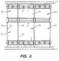
- FIG. 3 schematically illustrate three variants of combinations of modules made from a basic module and / or an extension of this basic module.
- a basic module 30 is used which is substantially identical to that represented by FIG. 2.
- a module 130 is superimposed which derives from the basic module 30 by a simple reduction the height of columns 31a, 31b, 31c and 31d.
- two identical modules 230 which derive from the basic module 30 because the longitudinal coupling elements 34 and 35 have been enlarged relative to those of the basic module, which allows the setting place two intermediate wheels A and B respectively and significantly increases the storage capacity of the installation.
- two identical modules 330 have been superimposed on the modules 230. They differ from the modules 230 in that the height of the columns has been reduced to be equal to that of the columns of the module 130.
- FIG. 4 illustrates another embodiment which optimally exploits a space delimited by four levels N1, N2, N3 and N4. It can be stated at the outset that storage devices of the type known could not be used in a room with such complex geometry and that this use would require the user to undertake costly masonry transformations and requiring the immobilization of the line.
- This embodiment consists of a base module 30 supplemented by three modules 230, as defined with reference to FIG. 3, juxtaposed and superimposed and by a module 130 superimposed on the base module 30 as well as a module 330 superimposed on two modules 230.
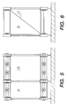
- FIG. 5 illustrates a relatively simple embodiment which consists of a basic module 30 juxtaposed with a module 230.
- FIG. 6 shows a side view of the installation of Figure 5. It will be noted in particular the existence of a spider 50 which contributes to stabilize this installation.
- This modular design allows adaptation to all sites and all applications and also allows for an evolution of the installation, in particular an increase in the storage volume according to an increase in needs.
- the distance between two gear wheels A and between two gear wheels B is constant. It is linked to the minimum spacing between the gondolas of two adjacent columns, this minimum spacing being determined in such a way that these gondolas do not collide with one another during their movements. It follows from the fact that the toothed wheels A are equidistant, that the length of the lower longitudinal coupling elements 34 is standard for a type of module. For example, for the basic module 30, this length is approximately equal to twice the distance between two gear wheels A or 2 d if d is the distance between two gear wheels A. In the case of modules 230 and 330, this length is equal to 3 d .
- the length of the longitudinal coupling elements is between d and n d , where n is an integer greater than 1.
- the exchanger 100 includes a device 101 for introducing clean tablets and a device 102 for removing tablets. dirty.
- the operating sequences or the operating mode of these devices can be very varied as required.
- the exchange of the tablets is of course carried out when the products have previously been removed. This exchange can, for example, concern one in ten gondolas for each complete installation cycle, so that after ten cycles all the gondolas have been cleaned.
- the device 101 for introducing the clean tablets comprises a magazine 103 in which is stacked a series of clean tablets 15 and a pusher 104 arranged to push the upper tablet 15 from the stack, to slide it onto a table 105 and to put it in place in the empty space opposite 106 of the gondola 14. This empty space was created by the sampling device 102 which previously removed a dirty tablet at the corresponding location.
- This removal device 102 comprises a magazine 107 in which is stacked a series of tablets 15 to be cleaned, and a claw 108 arranged to remove a tablet from the gondola, to slide it onto a table 109 and to bring it above the stack of shelves of the magazine 107.
- a shelf 15 is deposited, the magazine 107 descends by a height corresponding to the thickness of the ends of a shelf.
- the stack rises by a height corresponding to this same thickness.
- the two magazines 103 and 107 are mounted on a carriage 110 which can be removed manually or automatically.
- FIG. 8 shows the drive mechanism of the automatic exchanger 100.
- the device 101 and the device 102 each comprise a drive motor, respectively 101a and 102a, arranged to each drive a toothed belt, respectively 101b and 102b.
- These belts each carry a console, respectively 101c and 102c which serves as a support respectively for the stack of clean tablets and the stack of dirty tablets.
- the motors are controlled to advance step by step. One of the consoles goes up when the other goes down.
- the stack of clean socks is normally full when the stack of dirty shelves is empty and vice versa.
- the two introduction and sampling devices can be separated.
- a solution can for example be envisaged if it is desired to place rows or beds of products on the shelves before placing these shelves in the gondolas.
- the device for removing dirty tablets is installed after the product discharge station and the device for introducing clean tablets is installed downstream of the separate device for depositing products.
- Such an embodiment allows the storage of products in beds which has never been possible with known installations.
- the deposition station 18 is arranged to deposit beds of products 16.
- This station is provided with a supply device 8 for empty shelves and with a loading device 9 product beds.
- She further comprises a ribbon 18a and a guide 18b having a comb-like structure in order to be able to individually retain the products in such a way that they keep their arrangement in beds during their transfer to the shelves 15.
- These shelves are brought by a device such than previously and are placed on the gondolas after being loaded with products arranged in beds.
- the recovery of the products is done in a similar manner in the receiving station with a device for unloading the tablets and a device for recovering the empty tablets.
Landscapes
- Engineering & Computer Science (AREA)
- Mechanical Engineering (AREA)
- Warehouses Or Storage Devices (AREA)
- Forklifts And Lifting Vehicles (AREA)
- Spinning Or Twisting Of Yarns (AREA)
- Catching Or Destruction (AREA)
- Centrifugal Separators (AREA)
- Storage Of Fruits Or Vegetables (AREA)
- Devices That Are Associated With Refrigeration Equipment (AREA)
- Intermediate Stations On Conveyors (AREA)
- Assembled Shelves (AREA)
Claims (18)
- Vorrichtung zur pendelnden Speicherung (10) von Gegenständen, besonders von Lebensmitteln und vor allem von Schokoladetafeln oder etwas ähnlichem, wobei diese Produkte auf Tabletts (15) abgelegt sind, die horizontal an Gondeln (14) angeordnet sind, welche horizontal an zwei zueinander parallelen, sich langsam auf einer geschlossenen Bahn fortbewegenden Ketten (12,13) aufgehängt sind, wobei diese Einrichtung einen Zuführungsabschnitt (17) aufweist, mit einer Station (18) zum Auflegen der Produkte auf die Tabletts, anschließend eine Abnahmestation (19) für diese Produkte, die dazu dient, die Tabletts zu entleeren, und einen Abschnitt (20) für die Rückführung, in welchem die Tabletts leer von der Abnahmestation zur Station zum Auflegen zurückgeführt werden, bei der das Gestell (11) aus mindestens einer Grundeinheit (30) besteht, die aus vier vertikalen Säulen (31a,31b,31c,31d) besteht, und die untereinander paarweise durch untere (34) bzw. obere (35) Längsverbindungselemente verbunden sind, und durch untere (36) bzw. obere (37) Querverbindungselemente, wobei die vertikalen Säulen an jedem ihrer Enden jeweils vier untere (32a,32b,32c,32d) und obere (33a,33b,33c,33d) Verbindungselemente aufweisen, wobei diese Verbindungselemente mit Kupplungseinrichcungen versehen sind, die dazu dienen, die Montage von benachbarten und/oder übereinanderstehenden Einheiten zu gewährleisten.
- Vorrichtung nach Anspruch 1,
dadurch gekennzeichnet, daß
die unteren Verbindungselemente (32a,32b,32c,32d) so ausgeführt sind, daß sie ein unteres gezahntes Rad (A) tragen können, und daß die oberen Verbindungselemente (33a,33b,33c,33d) so ausgeführt sind, daß sie ein oberes gezahntes Rad (B) für die Kettenführung tragen können. - Vorrichtung nach Anspruch 1,
dadurch gekennzeichnet, daß
die unteren Längsverbindungselemente (34) so ausgeführt sind, daß sie mindestens ein zusätzliches gezahntes Rad (A) tragen können, und daß die oberen Längsverbindungselemente (35) so ausgeführt sind, daß sie mindestens ein zusätzliches gezahntes Rad (B) für die Kettenführung tragen können. - Vorrichtung nach Anspruch 2,
dadurch gekennzeichnet, daß
der Abstand zwischen zwei benachbarten, gezahnten, unteren Rädern (A) und der Abstand zwischen zwei benachbarten, oberen, gezahnten Rädern (B) einen konstanten Wert d hat. - Vorrichtung nach Anspruch 3,
dadurch gekennzeichnet, daß
die unteren (34) und die oberen (35) Längsverbindungselemente eine Länge haben, die etwa gleich einem Vielfachen des Abstandes d ist, der zwei benachbarte gezahnte Räder (A bzw. B) trennt. - Vorrichtung nach einem der vorhergehenden Ansprüche,
dadurch gekennzeichnet, daß
sie mehrere nebeneinander und/oder übereinander befindliche Einheiten aufweist, wobei diese Einheiten paarweise durch gemeinsame Verbindungselemente gekuppelt sind, und daß die Längskupplungselemente (34,35) Längen von d und nd haben, wo n eine ganze Zahl größer als 1 ist. - Vorrichtung nach Anspruch 1,
dadurch gekennzeichnet, daß
die Verbindungselemente (32a,32b,32c,32d; 33a,33b, 33c,33d) aus Klötzen bestehen, die an den Enden der vertikalen Säulen (31a,31b,31c,31d) befestigt sind, wobei diese Klötze die Form eines Parallelepipeds mit quadratischem oder rechteckigem Querschnitt haben und vier ebene Flächen aufweisen, die so ausgeführt sind, daß man die unteren (34) und oberen (35) Längsverbindungselemente befestigen kann, sowie auch die unteren (36) und oberen (37) Querverbindungselemente. - Vorrichtung nach Anspruch 7,
dadurch gekennzeichnet, daß
die Längsverbindungselemente eine Traverse (34a, 35a) aufweisen, welche die gezahnten Räder (A,B) trägt, und zwei Versteifungsstäbe (38,39), die jeweils beiderseits der Traverse angeordnet sind. - Vorrichtung nach Anspruch 7,
dadurch gekennzeichnet, daß
die Verbindungselemente (32a,32b,32c,32d; 33a,33b, 33c,33d) so ausgeführt sind, daß jedes ein gezahntes Rad (A,B) tragen kann. - Vorrichtung nach Anspruch 1,
dadurch gekennzeichnet, daß
sie mindestens einen automatischen Tablettwechsler (100) aufweist. - Vorrichtung nach Anspruch 10,
dadurch gekennzeichnet, daß
dieser Wechsler (100) eine Vorrichtung (101) zum Zuführen von gereinigten Tabletts und eine Vorrichtung (102) für die Entnahme der ungereinigten Tabletts aufweist. - Vorrichtung nach Anspruch 11,
dadurch gekennzeichnet, daß
die Vorrichtung (101) zum Zuführen von gereinigten Tabletts und die Vorrichtung zum Entnehmen von ungereinigten Tabletts nach der Station für den Austrag der Produkte angeordnet ist. - Vorrichtung nach Anspruch 11,
dadurch gekennzeichnet, daß
die Vorrichtung (101) für die Zuführung der gereinigten Tabletts nach einer separaten Station für die Lagerung der Produkte installiert ist, und daß die Vorrichtung für die Entnahme von ungereinigten Tabletts hinter der Station für den Austrag der Produkte installiert ist. - Vorrichtung nach Anspruch 11,
dadurch gekennzeichnet, daß
die Vorrichtung (101) für die Zuführung von gereinigten Tabletts einen Schieber (104) aufweist, der dazu dient, ein auf einem Stapel von gereinigten Tabletts in einem Magazin (103) liegendes Tablett in einen freien Raum einer Gondel (14) zu schieben. - Vorrichtung nach Anspruch 11,
dadurch gekennzeichnet, daß
die Vorrichtung zum Entnehmen von Tabletts einen Haken (108) aufweist, der dazu dient, ein ungereinigtes Tablett aus einer Gondel (14) zu ziehen und es auf einen Stapel von ungereinigten Tabletts in einem Magazin (107) zu bringen. - Vorrichtung nach den Ansprüchen 14 und 15,
dadurch gekennzeichnet, daß
die Magazine (103 und 107) einen Zahnriemen (101b, 102b) aufweisen, der von einem Antriebsmotor (101a,102a) bewegt wird, und eine Konsole (101c, 102c), welche die Stapel der gereinigten und der ungereinigten Tabletts trägt. - Vorrichtung nach Anspruch 10,
dadurch gekennzeichnet, daß
der automatische Tablettwechsler eine Zuführvorrichtung (8) für leere zu beschickende Tabletts, die in der Lagerungsstation (18) angeordnet ist, und eine Vorrichtung zum Rückführen der leeren Tabletts aufweist. - Vorrichtung nach Anspruch 17,
dadurch gekennzeichnet, daß
die Zuführvorrichtung (8) für die leeren zu beschickenden Tabletts mit einer Beschickungsvorrichtung (9) für ganze Lagen von Produkten verbunden ist, und daß die Vorrichtung zur Rücknahme von entleerten Tabletts mit einer Vorrichtung zum lageweisen Entnehmen von Produkten, identisch mit der Beschickungsvorrichtung (9), verbunden ist.
Applications Claiming Priority (3)
| Application Number | Priority Date | Filing Date | Title |
|---|---|---|---|
| FR9405711A FR2719569B1 (fr) | 1994-05-03 | 1994-05-03 | Installation de stockage pendulaire. |
| FR9405711 | 1994-05-03 | ||
| PCT/CH1995/000095 WO1995029861A1 (fr) | 1994-05-03 | 1995-05-02 | Installation de stockage pendulaire |
Publications (2)
| Publication Number | Publication Date |
|---|---|
| EP0706491A1 EP0706491A1 (de) | 1996-04-17 |
| EP0706491B1 true EP0706491B1 (de) | 1997-12-10 |
Family
ID=9463054
Family Applications (1)
| Application Number | Title | Priority Date | Filing Date |
|---|---|---|---|
| EP95915731A Expired - Lifetime EP0706491B1 (de) | 1994-05-03 | 1995-05-02 | Vorrichtung zur pendelnden speicherung |
Country Status (8)
| Country | Link |
|---|---|
| US (1) | US5772002A (de) |
| EP (1) | EP0706491B1 (de) |
| JP (1) | JPH09503474A (de) |
| AT (1) | ATE160999T1 (de) |
| AU (1) | AU2252395A (de) |
| DE (1) | DE69501200T2 (de) |
| FR (1) | FR2719569B1 (de) |
| WO (1) | WO1995029861A1 (de) |
Families Citing this family (1)
| Publication number | Priority date | Publication date | Assignee | Title |
|---|---|---|---|---|
| CN111498365A (zh) * | 2020-05-19 | 2020-08-07 | 宁波智能制造技术研究院有限公司 | 一种圆棒型模具的储存装置 |
Family Cites Families (8)
| Publication number | Priority date | Publication date | Assignee | Title |
|---|---|---|---|---|
| GB262788A (de) * | 1925-12-08 | |||
| US2823811A (en) * | 1955-06-29 | 1958-02-18 | Capitol Prod Corp | Proofer |
| BE626027A (de) * | 1962-12-13 | 1963-04-01 | ||
| US3851764A (en) * | 1973-03-29 | 1974-12-03 | Diebold Inc | Power file construction |
| DE3148473A1 (de) * | 1981-12-08 | 1983-06-16 | Fraunhofer-Gesellschaft zur Förderung der angewandten Forschung e.V., 8000 München | Einrichtung zum speichern von teilen mit flexibler speicherkapazitaet |
| JPS61265224A (ja) * | 1985-05-20 | 1986-11-25 | Oki Electric Ind Co Ltd | 部品自動ハンドリング装置 |
| IT1234229B (it) * | 1988-12-16 | 1992-05-06 | Axis Spa | Metodi ed apparecchiature per realizzare parti di motori elettrici impieganti pallets con supporto amovibile del pezzo in lavorazione |
| DE4135241C1 (de) * | 1991-10-25 | 1993-05-13 | Kloeckner Haensel Gmbh, 3000 Hannover, De |
-
1994
- 1994-05-03 FR FR9405711A patent/FR2719569B1/fr not_active Expired - Fee Related
-
1995
- 1995-05-02 US US08/571,911 patent/US5772002A/en not_active Expired - Fee Related
- 1995-05-02 AT AT95915731T patent/ATE160999T1/de not_active IP Right Cessation
- 1995-05-02 AU AU22523/95A patent/AU2252395A/en not_active Abandoned
- 1995-05-02 DE DE69501200T patent/DE69501200T2/de not_active Expired - Fee Related
- 1995-05-02 WO PCT/CH1995/000095 patent/WO1995029861A1/fr not_active Ceased
- 1995-05-02 JP JP7527917A patent/JPH09503474A/ja active Pending
- 1995-05-02 EP EP95915731A patent/EP0706491B1/de not_active Expired - Lifetime
Also Published As
| Publication number | Publication date |
|---|---|
| AU2252395A (en) | 1995-11-29 |
| EP0706491A1 (de) | 1996-04-17 |
| JPH09503474A (ja) | 1997-04-08 |
| WO1995029861A1 (fr) | 1995-11-09 |
| DE69501200D1 (de) | 1998-01-22 |
| FR2719569A1 (fr) | 1995-11-10 |
| US5772002A (en) | 1998-06-30 |
| ATE160999T1 (de) | 1997-12-15 |
| DE69501200T2 (de) | 1998-04-16 |
| FR2719569B1 (fr) | 1996-07-19 |
Similar Documents
| Publication | Publication Date | Title |
|---|---|---|
| EP1329398B1 (de) | Verfahren und Anlage zur automatischen Lagerung und Verteilung von verschiedenen Stückgütern oder Gegenständen | |
| EP3112298B1 (de) | Vorrichtung und verfahren zur versorgung eines zwischenförderer | |
| EP0593382B1 (de) | Verfahren zum automatischen und kontinuierlichen Etikettieren von Gegenständen wie Früchten oder Gemüse und Vorrichtung dafür | |
| FR2915977A1 (fr) | Navette avec plateau pour entrepot de stockage et/ou de preparation logistique. | |
| CA3046230C (fr) | Dispositif de transport de type noria de plaques supports de produits de boulangerie ou similaires | |
| EP0706493B1 (de) | Hängespeicher | |
| FR2968637A1 (fr) | Procede et dispositif d'encaissage destines a realiser un encaissage sequentiel de lots de produits a l'interieur de receptacles de conditionnement. | |
| EP1812325B1 (de) | Verfahren und anlage zur automatischen gepäckhandhabung | |
| EP0706490B1 (de) | Hängspeicher | |
| EP0706491B1 (de) | Vorrichtung zur pendelnden speicherung | |
| FR2924104A1 (fr) | Systeme de repartition de barres de produits alimentaires | |
| EP3511135B1 (de) | Schneideanlage von lebensmittelprodukten, die mit mitteln zum füllen einer rinne ausgestattet ist | |
| FR2478024A1 (fr) | Appareil pour manipuler des lots de biscuits | |
| FR2719567A1 (fr) | Installation de stockage pendulaire. | |
| EP0315263B1 (de) | Mobiles Regalmagazin für die Reifung von synthetischen Quellrohlingen | |
| WO1993006010A1 (fr) | Procede de decoupe de preparation culinaire en portions et d'emballage desdites portions, son dispositif et ses utilisations | |
| FR2670474A1 (fr) | Appareil permettant de distribuer un a un des articles stockes sous la forme d'un empilement. | |
| EP3523228A1 (de) | Bewegung von produkten auf einer linie | |
| FR2606381A1 (fr) | Procede et dispositif de chargement de produits bruts ou conditionnes sur un support de stockage | |
| FR2607116A1 (fr) | Magasin mecanise comprenant une pluralite de cellules de stockage d'articles | |
| FR2844259A1 (fr) | Procede, dispositif et installation de palettisation de piles de plateaux contenant des articles fragiles | |
| WO2018083413A1 (fr) | Dispositif de manutention de produits | |
| BE562838A (de) | ||
| FR2865465A1 (fr) | Installation de manutention de produits cylindriques, en particulier de produits fragiles genre fromages conformes en buche | |
| FR2876364A1 (fr) | Installation de traitement automatique des bagages |
Legal Events
| Date | Code | Title | Description |
|---|---|---|---|
| PUAI | Public reference made under article 153(3) epc to a published international application that has entered the european phase |
Free format text: ORIGINAL CODE: 0009012 |
|
| 17P | Request for examination filed |
Effective date: 19960201 |
|
| AK | Designated contracting states |
Kind code of ref document: A1 Designated state(s): AT BE CH DE FR GB IT LI |
|
| GRAG | Despatch of communication of intention to grant |
Free format text: ORIGINAL CODE: EPIDOS AGRA |
|
| 17Q | First examination report despatched |
Effective date: 19970305 |
|
| GRAG | Despatch of communication of intention to grant |
Free format text: ORIGINAL CODE: EPIDOS AGRA |
|
| GRAH | Despatch of communication of intention to grant a patent |
Free format text: ORIGINAL CODE: EPIDOS IGRA |
|
| GRAH | Despatch of communication of intention to grant a patent |
Free format text: ORIGINAL CODE: EPIDOS IGRA |
|
| GRAA | (expected) grant |
Free format text: ORIGINAL CODE: 0009210 |
|
| AK | Designated contracting states |
Kind code of ref document: B1 Designated state(s): AT BE CH DE FR GB IT LI |
|
| PG25 | Lapsed in a contracting state [announced via postgrant information from national office to epo] |
Ref country code: AT Free format text: LAPSE BECAUSE OF FAILURE TO SUBMIT A TRANSLATION OF THE DESCRIPTION OR TO PAY THE FEE WITHIN THE PRESCRIBED TIME-LIMIT Effective date: 19971210 |
|
| REF | Corresponds to: |
Ref document number: 160999 Country of ref document: AT Date of ref document: 19971215 Kind code of ref document: T |
|
| REG | Reference to a national code |
Ref country code: CH Ref legal event code: EP |
|
| GBT | Gb: translation of ep patent filed (gb section 77(6)(a)/1977) |
Effective date: 19971212 |
|
| REG | Reference to a national code |
Ref country code: CH Ref legal event code: NV Representative=s name: CABINET ROLAND NITHARDT CONSEILS EN PROPRIETE INDU |
|
| REF | Corresponds to: |
Ref document number: 69501200 Country of ref document: DE Date of ref document: 19980122 |
|
| ITF | It: translation for a ep patent filed | ||
| PG25 | Lapsed in a contracting state [announced via postgrant information from national office to epo] |
Ref country code: BE Free format text: LAPSE BECAUSE OF NON-PAYMENT OF DUE FEES Effective date: 19980531 |
|
| REG | Reference to a national code |
Ref country code: CH Ref legal event code: PFA Free format text: SAPAL, SOCIETE ANONYME DES PLIEUSES AUTOMATIQUES TRANSFER- SIG PACK SAPAL S.A. |
|
| REG | Reference to a national code |
Ref country code: FR Ref legal event code: CD |
|
| PLBE | No opposition filed within time limit |
Free format text: ORIGINAL CODE: 0009261 |
|
| STAA | Information on the status of an ep patent application or granted ep patent |
Free format text: STATUS: NO OPPOSITION FILED WITHIN TIME LIMIT |
|
| BERE | Be: lapsed |
Owner name: DES PLIEUSES AUTOMATIQUES S.A. SAPAL Effective date: 19980531 |
|
| 26N | No opposition filed | ||
| PGFP | Annual fee paid to national office [announced via postgrant information from national office to epo] |
Ref country code: DE Payment date: 20010504 Year of fee payment: 7 |
|
| PGFP | Annual fee paid to national office [announced via postgrant information from national office to epo] |
Ref country code: GB Payment date: 20010523 Year of fee payment: 7 |
|
| PGFP | Annual fee paid to national office [announced via postgrant information from national office to epo] |
Ref country code: FR Payment date: 20010529 Year of fee payment: 7 |
|
| PGFP | Annual fee paid to national office [announced via postgrant information from national office to epo] |
Ref country code: CH Payment date: 20010823 Year of fee payment: 7 |
|
| REG | Reference to a national code |
Ref country code: GB Ref legal event code: IF02 |
|
| PG25 | Lapsed in a contracting state [announced via postgrant information from national office to epo] |
Ref country code: GB Free format text: LAPSE BECAUSE OF NON-PAYMENT OF DUE FEES Effective date: 20020502 |
|
| PG25 | Lapsed in a contracting state [announced via postgrant information from national office to epo] |
Ref country code: LI Free format text: LAPSE BECAUSE OF NON-PAYMENT OF DUE FEES Effective date: 20020531 Ref country code: CH Free format text: LAPSE BECAUSE OF NON-PAYMENT OF DUE FEES Effective date: 20020531 |
|
| PG25 | Lapsed in a contracting state [announced via postgrant information from national office to epo] |
Ref country code: DE Free format text: LAPSE BECAUSE OF NON-PAYMENT OF DUE FEES Effective date: 20021203 |
|
| GBPC | Gb: european patent ceased through non-payment of renewal fee |
Effective date: 20020502 |
|
| REG | Reference to a national code |
Ref country code: CH Ref legal event code: PL |
|
| PG25 | Lapsed in a contracting state [announced via postgrant information from national office to epo] |
Ref country code: FR Free format text: LAPSE BECAUSE OF NON-PAYMENT OF DUE FEES Effective date: 20030131 |
|
| REG | Reference to a national code |
Ref country code: FR Ref legal event code: ST |
|
| PG25 | Lapsed in a contracting state [announced via postgrant information from national office to epo] |
Ref country code: IT Free format text: LAPSE BECAUSE OF NON-PAYMENT OF DUE FEES;WARNING: LAPSES OF ITALIAN PATENTS WITH EFFECTIVE DATE BEFORE 2007 MAY HAVE OCCURRED AT ANY TIME BEFORE 2007. THE CORRECT EFFECTIVE DATE MAY BE DIFFERENT FROM THE ONE RECORDED. Effective date: 20050502 |