EP0706603B1 - Leve-glace a cable - Google Patents
Leve-glace a cable Download PDFInfo
- Publication number
- EP0706603B1 EP0706603B1 EP94919674A EP94919674A EP0706603B1 EP 0706603 B1 EP0706603 B1 EP 0706603B1 EP 94919674 A EP94919674 A EP 94919674A EP 94919674 A EP94919674 A EP 94919674A EP 0706603 B1 EP0706603 B1 EP 0706603B1
- Authority
- EP
- European Patent Office
- Prior art keywords
- cable
- window lifter
- window
- pull
- lifter according
- Prior art date
- Legal status (The legal status is an assumption and is not a legal conclusion. Google has not performed a legal analysis and makes no representation as to the accuracy of the status listed.)
- Expired - Lifetime
Links
- 125000006850 spacer group Chemical group 0.000 claims description 27
- 230000001681 protective effect Effects 0.000 claims description 5
- 238000006073 displacement reaction Methods 0.000 claims description 2
- 238000003780 insertion Methods 0.000 claims description 2
- 230000037431 insertion Effects 0.000 claims description 2
- 230000000717 retained effect Effects 0.000 claims 3
- 229920002994 synthetic fiber Polymers 0.000 claims 1
- 238000010276 construction Methods 0.000 abstract 1
- 210000002445 nipple Anatomy 0.000 description 6
- 238000000926 separation method Methods 0.000 description 5
- 230000000694 effects Effects 0.000 description 1
- 230000002349 favourable effect Effects 0.000 description 1
- 239000002184 metal Substances 0.000 description 1
Images
Classifications
-
- F—MECHANICAL ENGINEERING; LIGHTING; HEATING; WEAPONS; BLASTING
- F16—ENGINEERING ELEMENTS AND UNITS; GENERAL MEASURES FOR PRODUCING AND MAINTAINING EFFECTIVE FUNCTIONING OF MACHINES OR INSTALLATIONS; THERMAL INSULATION IN GENERAL
- F16C—SHAFTS; FLEXIBLE SHAFTS; ELEMENTS OR CRANKSHAFT MECHANISMS; ROTARY BODIES OTHER THAN GEARING ELEMENTS; BEARINGS
- F16C1/00—Flexible shafts; Mechanical means for transmitting movement in a flexible sheathing
- F16C1/26—Construction of guiding-sheathings or guiding-tubes
- F16C1/262—End fittings; Attachment thereof to the sheathing or tube
-
- E—FIXED CONSTRUCTIONS
- E05—LOCKS; KEYS; WINDOW OR DOOR FITTINGS; SAFES
- E05F—DEVICES FOR MOVING WINGS INTO OPEN OR CLOSED POSITION; CHECKS FOR WINGS; WING FITTINGS NOT OTHERWISE PROVIDED FOR, CONCERNED WITH THE FUNCTIONING OF THE WING
- E05F11/00—Man-operated mechanisms for operating wings, including those which also operate the fastening
- E05F11/38—Man-operated mechanisms for operating wings, including those which also operate the fastening for sliding windows, e.g. vehicle windows, to be opened or closed by vertical movement
- E05F11/48—Man-operated mechanisms for operating wings, including those which also operate the fastening for sliding windows, e.g. vehicle windows, to be opened or closed by vertical movement operated by cords or chains or other flexible elongated pulling elements, e.g. tapes
- E05F11/481—Man-operated mechanisms for operating wings, including those which also operate the fastening for sliding windows, e.g. vehicle windows, to be opened or closed by vertical movement operated by cords or chains or other flexible elongated pulling elements, e.g. tapes for vehicle windows
- E05F11/483—Man-operated mechanisms for operating wings, including those which also operate the fastening for sliding windows, e.g. vehicle windows, to be opened or closed by vertical movement operated by cords or chains or other flexible elongated pulling elements, e.g. tapes for vehicle windows by cables
- E05F11/488—Man-operated mechanisms for operating wings, including those which also operate the fastening for sliding windows, e.g. vehicle windows, to be opened or closed by vertical movement operated by cords or chains or other flexible elongated pulling elements, e.g. tapes for vehicle windows by cables with two cable connections to the window glass
-
- E—FIXED CONSTRUCTIONS
- E05—LOCKS; KEYS; WINDOW OR DOOR FITTINGS; SAFES
- E05Y—INDEXING SCHEME ASSOCIATED WITH SUBCLASSES E05D AND E05F, RELATING TO CONSTRUCTION ELEMENTS, ELECTRIC CONTROL, POWER SUPPLY, POWER SIGNAL OR TRANSMISSION, USER INTERFACES, MOUNTING OR COUPLING, DETAILS, ACCESSORIES, AUXILIARY OPERATIONS NOT OTHERWISE PROVIDED FOR, APPLICATION THEREOF
- E05Y2600/00—Mounting or coupling arrangements for elements provided for in this subclass
- E05Y2600/50—Mounting methods; Positioning
- E05Y2600/52—Toolless
- E05Y2600/53—Snapping
-
- E—FIXED CONSTRUCTIONS
- E05—LOCKS; KEYS; WINDOW OR DOOR FITTINGS; SAFES
- E05Y—INDEXING SCHEME ASSOCIATED WITH SUBCLASSES E05D AND E05F, RELATING TO CONSTRUCTION ELEMENTS, ELECTRIC CONTROL, POWER SUPPLY, POWER SIGNAL OR TRANSMISSION, USER INTERFACES, MOUNTING OR COUPLING, DETAILS, ACCESSORIES, AUXILIARY OPERATIONS NOT OTHERWISE PROVIDED FOR, APPLICATION THEREOF
- E05Y2900/00—Application of doors, windows, wings or fittings thereof
- E05Y2900/50—Application of doors, windows, wings or fittings thereof for vehicles
- E05Y2900/53—Type of wing
- E05Y2900/55—Windows
Definitions
- the invention relates to a cable window regulator according to the preamble of claim 1.
- Such a cable window regulator is already known from FR-PS 11 99 784.
- This window lifter has a drive unit for the cable of the cable, which is guided over a vertical distance by means of deflection parts and is connected in this section to a driver which holds the window pane.
- the driver has no separate guide and is fixed to the cable by means of a clamping piece.
- the type of connection between the driver and the cable is structurally complex in this known embodiment, with the additional risk of the connection between the cable and the driver being unintentionally released.
- Another cable window regulator is known from US-A-4 920 697.
- a cross member is provided, which is connected to the window pane, which is connected at both ends to drivers, which in turn are attached to the cable.
- DE 40 15 774 A1 apparently discloses a window adjusting device with a holder which can be moved up and down by means of a cable and which is connected to the window pane.
- the holder is not only connected to the cable, but is also guided in a guide rail by means of a guide roller.
- a connecting piece is provided with a receiving recess into which a clamping piece attached to the cable can be inserted.
- the connecting piece is fastened to the holder in that a pin provided on the connecting piece is inserted and secured through a hole in the holder.
- a cable window regulator for motor vehicles which has a drive unit with two outlets for the cable, which is laid endlessly in two intersecting loops.
- the rope is guided over four deflection pulleys or bends, which are mounted on the corner areas of two spaced-apart guide rails.
- Driver plates for the window pane are slidably guided on the guide rails, on which the cable pull moving the window pane acts.
- the pane itself is guided with its front edges in further guides of the door, as is known, for example, from DE 39 21 289 C1.
- the disadvantage here is the design effort and, above all, the over-determination of the pane guide as a whole, since the guides of the window lifter or the driver and the pane guides must be exactly matched to one another.
- the invention has for its object to develop a cable window regulator of the type mentioned in such a way that simple assembly and safe and permanent fixing of the cable is guaranteed on the driver.
- a particularly simple connection of the cable to the driver is achieved in that the driver can be inserted into a recess in the plate-shaped base element, the driver being fixed to the cable without tools.
- the clamping piece has a chamber for receiving a holding element firmly connected to the cable pull and openings for the cable formed on the end faces of the chamber, a simple and secure fixing between the Cable and the basic element possible.
- the cable between the basic element of the driver is fixed in that the cable, with its holding element, for example in the form of a nipple, is passed through the recess in the basic element in the manner of a loop, then the holding element is inserted into the chamber of the clamping piece and then the Clamping piece is pressed into the recess on the base element.
- the rope is immovably connected to the driver, thus creating the connection between the cable and the driver.
- This special type of fixing the cable to the holding element by means of the clamping piece also has the effect that unintentional loosening of the cable from the driver is reliably avoided.
- the clamping piece can be inserted into the recess from the top of the basic element, while the cable is guided to the side of the chamber of the clamping piece along the underside of the basic element, an unintentional escape of the cable from the chamber of the clamping piece is not possible. Furthermore, due to the special guidance on the base element, the cable pull itself acts as a safeguard against the accidental escape of the clamping piece from the recess in the base element.
- the cable is guided endlessly by the at least one driver. In this way, a simple adjustment possibility is achieved between the window pane and the driver to be fixed on the rope.
- the deflecting parts for the rope on the guide rails for the window pane are arranged, the design effort of the window lifter is significantly reduced. Overall, by eliminating the rails for guiding the driver or drivers connected to the window pane, overdetermination of the guide system is avoided and a more favorable torque of the drive reached. Another advantage is that the noise problems caused by the known window regulators due to stick-slip phenomena are no longer present.
- the measure that the clamping piece has latching lugs, which engage behind the base element in the region of the recess in a clamping manner, has proven to be particularly advantageous, as a result of which the assembly of the cable on the driver is further improved.
- the clamping piece for the purpose of assembly can be easily pressed into the recess of the basic element from the top of the basic element, the side of the chamber of the clamping piece emerging rope sections are guided through the slots to the bottom of the base element. Damage to the cable during assembly is thereby avoided safely and in a structurally simple manner.
- an adjustment device for the cable length of the cable is provided with a spacer that can be inserted in a separation point of the outer hose of the cable.
- the rope can initially have a certain amount of slack in order to be looped over the deflecting parts in a simple manner.
- the lots are removed after assembly by means of a spacer, which is inserted in the separation point of the cable.
- the adjusting device has a base body with a through hole for the cable pull and a longitudinal slot for inserting the spacer between the front ends of the outer tube formed by the separation point of the cable.
- the handling can be further improved in that the bore of the base body, preferably in the area of the longitudinal slot, has a stop for the outer tube of the cable, so that it is easier to pull the outer tube out of the area of the longitudinal slot.
- the fixing of the spacer on the base body can be realized in a particularly simple manner in that the spacer is held in the clamp seat, for example by means of locking and counter-locking means on the base body, so that the spacer can be inserted without tools.
- the spacer encompasses the base body with circular segment-shaped wall extensions and is preferably secured against axial displacement between two contact shoulders formed on the base body. In this way, undesired detachment of the spacer from the base body is avoided in any case.
- the spacer has a web-shaped extension with a longitudinal groove for receiving the cable, the end faces of the extension forming a stop for the ends of the protective hose of the cable in the region of the separation point.
- the base body and / or the spacer of the adjusting device and / or the clamping piece consist of plastic.
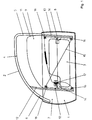
- the vehicle door as shown in Figure 1, has a lower door box 1 and an upper window frame 2.
- the door box 1 is closed on the outside by an outer door skin 3, while it is usually covered on the inside with a door inner lining.
- the door interior trim is removed, so that the window lifter arranged in the door box 1 is visible.
- the window frame 2 has an upper frame part 4, a rear frame part 5 and a front frame part 6.
- the door shown is usually pivotally attached to its front side 7 with a support column of a vehicle via hinges, not shown, while on the rear side 8 is a door lock part, not shown.
- the window frame 2 receives a window pane 9 which is adapted to its circumferential contour and is approximately half open in the illustration in FIG. 1.
- the window pane 9 is guided on its front edge 10 and on its rear edge 11 in a front and a rear guide rail 12, 13, respectively.
- a driver 14 is clamped onto the lower edge of the window pane 9, in the region of the corner, to which the cable 29 of a cable pull 15 is fastened.
- the cable 15 is guided over four deflecting parts in the form of deflecting rollers 16 which are fastened within the door box 1 at the upper and lower ends of the two guide rails 12, 13.
- the cable 15 runs, crosswise over the deflection rollers 16, to a shaft 17 of a window crank, not shown, or an electric drive. Depending on the direction of rotation of the shaft 17, the cable 29 is pulled in one or the other direction, so that the window pane 9 moves upwards or downwards via the drivers 14.
- the drivers 14 can be moved up and down with the cable 29 without separate guides.
- the driver 14 is guided solely via the window pane 9 or its guide rails 12, 13. This prevents overdeterminations in the pane guide.
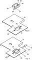
- the fixing of such a driver 14 on the cable 29 can be seen in FIGS. 2 and 3.
- the driver 14 has a plate-shaped base element 19, on which a receptacle, not shown, for the window pane 9 is arranged.
- the plate-shaped base element 19 has a recess 21, into which a clamping piece 20 designed as a clip can be clipped on. This can be done, for example, by the fact that 20 locking lugs 27 are formed on the clamping piece.
- the clamping piece 20 has a chamber 24 for receiving a holding element 30 which is fixedly connected to the cable 29.
- the holding element 30, which is designed in the form of a nipple, is preferably made of metal and is pressed immovably on the cable 29.
- the connection between the cable 29 and the window pane 9 takes place in that the cable 29 with the nipple 30 is looped through from below through the recess 21 of the basic element 19 in accordance with the representation of the plate-shaped basic element 19 in FIGS. 2 and 3.
- the nipple 30 is then inserted into the chamber 24 of the clamping piece 20, the cable sections extending on both sides of the nipple 30 being inserted into the openings 25 on the end faces of the clamping piece 20.
- the clamping piece 20 is pressed into the recess 21 of the base element 19, the rope sections extending on both sides of the nipple 30 being guided into the slots 22 provided in the base element 19 without the rope 29 being damaged.
- the rope 29 is immovably connected to the driver 14 and thus also the window 9 with the power window drive.
- the rope 29 initially has a certain amount of slack so that it can be looped over the deflection rollers 16 in a simple manner. After installing the rope 29, however, the lots must be removed again to ensure proper operation.
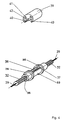
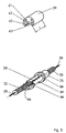
- a cable length adjusting device is inserted into the cable pull 15 according to FIGS. 4 and 5.
- the outer tube 32 of the cable 15 is interrupted and a base body 33 is inserted between the two ends of the protective tube 32.
- the base body 33 has one Bore 35 for the cable pull 15 with a longitudinal slot 38 for inserting a spacer 39 between the front ends of the outer tube 32 formed by the separation point.
- the cable 29 is of such a length that it can easily be laid over the deflection rollers 16.
- the protective tube 32 of the cable 15 is inserted into the longitudinal slot 38 of the base body 33 and is in contact with the stop 37 of the bore 35.
- the piece of protective tube 32 lying in the longitudinal slot 38 is pulled out of the longitudinal slot, so that only the rope 29 is present here, as is shown schematically in FIG.
- the spacer 39 is then placed between the two stop shoulders 36 on the base body 33 in such a way that the cable 29 lies in the longitudinal groove 42 formed on a web-shaped extension 41 of the spacer 39.
- the wall extensions 40 of the spacer 39 which is made of plastic, yield elastically in order to finally enclose the retraction on the base body 33 formed by the stop shoulders 36, i. w. complete flush with the stop shoulders 36. In this way, an unwanted detachment of the spacer 39 from the base body 33 is avoided.
- spacers 39 of different length L are also possible to use in order to compensate for additional tolerances.
- the spacer 39 is held by the cable tension and the associated contact pressure against its end face in the axial stop position on the stop 36 of the base body 37.
Landscapes
- Engineering & Computer Science (AREA)
- General Engineering & Computer Science (AREA)
- Health & Medical Sciences (AREA)
- Oral & Maxillofacial Surgery (AREA)
- Mechanical Engineering (AREA)
- Window Of Vehicle (AREA)
Abstract
Claims (12)
- Lève-glace équipé d'un système à câble pour des véhicules, notamment des véhicules automobiles, comportant une unité d'entraînement pour le câble (29) du système à câble (15), qui est guidé au moyen d'éléments de renvoi (16) sur au moins une section sensiblement verticale et est relié, dans cette partie, à un organe d'entraînement (14), sur lequel la vitre de fenêtre (9) est fixée de préférence par sa partie de bord inférieure, la vitre de fenêtre (9) étant guidée, par ses bords latéraux (10,11), dans des rails de guidage (12,13) disposés dans le véhicule ou dans la portière, et dans lequel au moins un organe d'entraînement (14) peut être soulevé et abaissé, sans guides séparés, au moyen du câble (29) et le système à câble (15) est retenu sur l'organe d'entraînement (14) à l'aide d'un organe de serrage (20), caractérisé en ce que l'organe d'entraînement (14) possède un élément de base (19) pourvu d'une ouverture (21), dans laquelle l'élément de serrage (20), qui peut être relié au câble (29), peut être inséré à partir du côté supérieur de l'élément de base (19), et en ce que l'élément de serrage (20) possède une chambre (24) servant à loger un élément de retenue (30) relié de façon fixe au câble, ainsi que des passages (25) formés dans les faces frontales de la chambre (24) et prévus pour le câble (29), le câble (29) étant guidé latéralement par rapport à la chambre (24) de l'élément de serrage (20), le long de la face inférieure de l'élément de base (19).
- Lève-glace selon la revendication 1, caractérisé en ce que le système à câble (15) est guidé sans fin à l'aide dudit au moins un organe d'entraînement (14).
- Lève-glace selon l'une des revendications précédentes, caractérisé en ce que les éléments de renvoi (16) pour le câble (29) sont disposés sur les rails de guidage (12,13) pour la vitre de fenêtre (9).
- Lève-glace selon l'une des revendications précédentes, caractérisé en ce que l'élément de serrage (20) comporte des becs d'encliquetage (27), qui s'engagent avec un effet de serrage derrière l'élément de base (19) dans la zone de l'évidement (21).
- Lève-glace selon l'une des revendications précédentes, caractérisé en ce que des fentes (22) pour le passage des parties du câble, qui sortent des deux côtés de l'élément de serrage (20), se raccordent, des deux côtés, à l'évidement (21) de l'élément de base (19).
- Lève-glace selon l'une des revendications précédentes, caractérisé en ce qu'il est prévu un dispositif de réglage de la longueur du câble du système à câble (15), qui est équipé d'une entretoise (39) pouvant être insérée dans une zone de séparation de la gaine extérieure (32) du système à câble (15).
- Lève-glace selon la revendication 6, caractérisé en ce que le dispositif de réglage possède un corps de base (33) qui est pourvu d'un perçage traversant (35) pour le système à câble (15) et comporte une fente longitudinale (38) pour l'insertion de l'entretoise (39) entre les extrémités frontales, définies par la zone de séparation, de la gaine extérieure (32) du système à câble (15).
- Lève-glace selon la revendication 7, caractérisé en ce que le perçage (35) possède, de préférence au niveau de la fente longitudinale (38), une butée (37) pour le tuyau extérieur (32) du système à câble (15).
- Lève-glace selon la revendication 7 ou 8, caractérisé en ce que l'entretoise (39) est maintenue à l'état serré contre le corps de base (33).
- Lève-glace selon l'une des revendications 6 à 9, caractérisé en ce que l'entretoise (39) enserre sur sa périphérie le corps de base (33) au moyen de prolongements de paroi (40) en forme de segments de cercle, et de préférence est bloquée contre tout déplacement axial entre deux épaulements de butée (36) formés sur le corps de base (33).
- Lève-glace selon l'une des revendications 6 à 10, caractérisé en ce que l'entretoise (39) possède un prolongement en forme de barrette (41) pourvu d'une rainure longitudinale (42) servant à loger le câble (29), les faces frontales du prolongement (41) formant une butée pour les extrémités de la gaine protectrice (32) du câble (15) au niveau de la zone de séparation.
- Lève-glace selon l'une des revendications 1 à 11, caractérisé en ce que le corps de base (33) et/ou l'entretoise (39) du dispositif de réglage et/ou l'élément de serrage (20) sont réalisés en matière plastique.
Applications Claiming Priority (3)
| Application Number | Priority Date | Filing Date | Title |
|---|---|---|---|
| DE4321735 | 1993-06-30 | ||
| DE4321735 | 1993-06-30 | ||
| PCT/EP1994/002141 WO1995001492A1 (fr) | 1993-06-30 | 1994-06-30 | Leve-glace a cable |
Publications (2)
| Publication Number | Publication Date |
|---|---|
| EP0706603A1 EP0706603A1 (fr) | 1996-04-17 |
| EP0706603B1 true EP0706603B1 (fr) | 1997-06-04 |
Family
ID=6491589
Family Applications (1)
| Application Number | Title | Priority Date | Filing Date |
|---|---|---|---|
| EP94919674A Expired - Lifetime EP0706603B1 (fr) | 1993-06-30 | 1994-06-30 | Leve-glace a cable |
Country Status (6)
| Country | Link |
|---|---|
| EP (1) | EP0706603B1 (fr) |
| BR (1) | BR9406871A (fr) |
| CA (1) | CA2165473A1 (fr) |
| DE (1) | DE59403041D1 (fr) |
| ES (1) | ES2104395T3 (fr) |
| WO (1) | WO1995001492A1 (fr) |
Cited By (1)
| Publication number | Priority date | Publication date | Assignee | Title |
|---|---|---|---|---|
| DE202007014817U1 (de) * | 2007-10-22 | 2009-03-05 | Brose Fahrzeugteile Gmbh & Co. Kg, Hallstadt | Seil-Fensterheber |
Families Citing this family (8)
| Publication number | Priority date | Publication date | Assignee | Title |
|---|---|---|---|---|
| FR2814772B1 (fr) * | 2000-09-29 | 2003-06-27 | Btr Sealing Systems France | Systeme d'entrainement et de guidage d'une vitre coulissante escamotable dans un caisson de carrosserie d'un vehicule automobile |
| FR2815667B1 (fr) * | 2000-10-24 | 2003-08-01 | Meritor Light Vehicle Sys Ltd | Systeme de fixation d'un leve-vitre sur une porte sans cadre de vehicule |
| FR2819285B1 (fr) * | 2001-01-11 | 2003-09-19 | Metzeler Automotive Profile | Systeme d'entrainement et de guidage d'une vitre coulissante dans un caisson de porte sans cadre d'un vehicule automobile |
| US7424788B2 (en) | 2001-04-26 | 2008-09-16 | Intier Automotive Closures Inc. | Universal cable window regulator assembly for vehicles |
| GB2410855A (en) * | 2004-02-04 | 2005-08-10 | Vodafone Plc | Telecommunication system communication sessions |
| DE102005002312B4 (de) * | 2005-01-17 | 2008-02-07 | Küster Automotive Door Systems GmbH | Mitnehmer für Seilzug-Fensterheber |
| WO2009147140A1 (fr) | 2008-06-03 | 2009-12-10 | Brose Fahrzeugteile Gmbh & Co. Kg, Coburg | Câble en fibre artificielle avec élément d'accouplement |
| CN103270235B (zh) * | 2010-12-22 | 2015-08-19 | 麦格纳覆盖件有限公司 | 车窗调节器组件 |
Family Cites Families (5)
| Publication number | Priority date | Publication date | Assignee | Title |
|---|---|---|---|---|
| FR1199784A (fr) * | 1957-07-18 | 1959-12-16 | Nsu Werke Ag | Fenêtre à manivelle pour voitures automobiles |
| FR1516936A (fr) * | 1967-01-19 | 1968-02-05 | Dba Sa | Perfectionnements aux mécanismes de lève-glace |
| DE8120936U1 (de) * | 1981-07-16 | 1982-02-11 | Metallwerk Max Brose Gmbh & Co, 8630 Coburg | Rohrfensterheber, insbesondere fuer kraftfahrzeugfenster |
| US4920697A (en) * | 1988-11-17 | 1990-05-01 | Hoover Universal Inc. | Dual drive window regulator mechanism |
| JPH03209042A (ja) * | 1990-01-08 | 1991-09-12 | Koito Mfg Co Ltd | 昇降装置 |
-
1994
- 1994-06-30 DE DE59403041T patent/DE59403041D1/de not_active Expired - Lifetime
- 1994-06-30 BR BR9406871A patent/BR9406871A/pt not_active Application Discontinuation
- 1994-06-30 CA CA002165473A patent/CA2165473A1/fr not_active Abandoned
- 1994-06-30 EP EP94919674A patent/EP0706603B1/fr not_active Expired - Lifetime
- 1994-06-30 WO PCT/EP1994/002141 patent/WO1995001492A1/fr not_active Ceased
- 1994-06-30 ES ES94919674T patent/ES2104395T3/es not_active Expired - Lifetime
Cited By (1)
| Publication number | Priority date | Publication date | Assignee | Title |
|---|---|---|---|---|
| DE202007014817U1 (de) * | 2007-10-22 | 2009-03-05 | Brose Fahrzeugteile Gmbh & Co. Kg, Hallstadt | Seil-Fensterheber |
Also Published As
| Publication number | Publication date |
|---|---|
| BR9406871A (pt) | 1996-03-26 |
| WO1995001492A1 (fr) | 1995-01-12 |
| DE59403041D1 (de) | 1997-07-10 |
| ES2104395T3 (es) | 1997-10-01 |
| EP0706603A1 (fr) | 1996-04-17 |
| CA2165473A1 (fr) | 1995-01-12 |
Similar Documents
| Publication | Publication Date | Title |
|---|---|---|
| DE4015774C2 (de) | Fensterstellvorrichtung | |
| DE3149073C2 (de) | Vorrichtung zur Führung und Betätigung eines vertikal verschiebbaren Fahrzeugfensters | |
| DE3532104A1 (de) | Vormontierte einbaueinheit fuer schiebehebedaecher von fahrzeugen | |
| DE19728708C2 (de) | Anordnung zum Einbau eines Kabelbaums in eine Automobiltür | |
| EP0706603B1 (fr) | Leve-glace a cable | |
| DE10039841A1 (de) | Vorrichtung zum Verbinden einer ein- und ausfahrbaren Kraftfahrzeug-Fensterscheibe mit einem Antriebselement | |
| EP0760302B1 (fr) | Système d'entraínement pour toits coulissants de véhicules automobiles | |
| DE19835579C2 (de) | Kabelführungseinrichtung an insbesondere einem Kraftfahrzeug | |
| DE19981927C1 (de) | Seilzug-Fensterheber für Fahrzeuge | |
| DE10123420B4 (de) | Antrieb für ein verstellbares Schließelement eines Fahrzeugdaches | |
| DE69609015T2 (de) | Einrastbarer Stützschaft für Seilrollen | |
| DE19730269C2 (de) | Vorrichtung zum Befestigen eines ersten Teils mit einem zweiten Teil | |
| DE69302527T2 (de) | Kraftfahrzeugfensterheber | |
| DE3805576C2 (de) | Befestigung für ein Seil-Umlenkstück an einer Führungsschiene eines Seil-Fensterhebers | |
| DE20213813U1 (de) | Führungsschienen-Anordnung für Seilfensterheber | |
| DE10340196B4 (de) | Schlossmoduleinrichtung für eine Kraftfahrzeugtür | |
| DE102009036780B4 (de) | Führungseinrichtung für eine seilzugbetätigte Verstellvorrichtung | |
| DE102009057022B4 (de) | Vorrichtung zum Führen von Reinigungsflüssigkeit | |
| DE4321616A1 (de) | Vorrichtung zum Verbinden eines Mitnehmers eines Fensterhebers mit einer Fensterscheibe | |
| DE102005030707A1 (de) | Fensterrollo für Kraftfahrzeuge mit formschlüssigem Anschlag auf dem Betätigungsglied | |
| DE8032764U1 (de) | Gekruemmtes abstuetzglied an bowdenzug-fensterhebern | |
| DE10162036C1 (de) | Vorrichtung zum Heben und Senken einer Fensterscheibe in einem Kraftfahrzeug | |
| DE102005047978B3 (de) | Antriebsgehäuse für ein bewegbares Fahrzeugteil | |
| DE202007008049U1 (de) | Führungsbaugruppe eines Kraftfahrzeugfensterhebers | |
| DE10127438C1 (de) | Seilzug-Fensterheber zum Verschieben einer Fensterscheibe mit Mitnehmer und verrastbarem Gleitelement |
Legal Events
| Date | Code | Title | Description |
|---|---|---|---|
| PUAI | Public reference made under article 153(3) epc to a published international application that has entered the european phase |
Free format text: ORIGINAL CODE: 0009012 |
|
| 17P | Request for examination filed |
Effective date: 19951124 |
|
| AK | Designated contracting states |
Kind code of ref document: A1 Designated state(s): DE ES FR GB |
|
| 17Q | First examination report despatched |
Effective date: 19960429 |
|
| GRAG | Despatch of communication of intention to grant |
Free format text: ORIGINAL CODE: EPIDOS AGRA |
|
| GRAH | Despatch of communication of intention to grant a patent |
Free format text: ORIGINAL CODE: EPIDOS IGRA |
|
| GRAH | Despatch of communication of intention to grant a patent |
Free format text: ORIGINAL CODE: EPIDOS IGRA |
|
| GRAA | (expected) grant |
Free format text: ORIGINAL CODE: 0009210 |
|
| AK | Designated contracting states |
Kind code of ref document: B1 Designated state(s): DE ES FR GB |
|
| GBT | Gb: translation of ep patent filed (gb section 77(6)(a)/1977) |
Effective date: 19970606 |
|
| REF | Corresponds to: |
Ref document number: 59403041 Country of ref document: DE Date of ref document: 19970710 |
|
| REG | Reference to a national code |
Ref country code: ES Ref legal event code: FG2A Ref document number: 2104395 Country of ref document: ES Kind code of ref document: T3 |
|
| ET | Fr: translation filed | ||
| PLBE | No opposition filed within time limit |
Free format text: ORIGINAL CODE: 0009261 |
|
| STAA | Information on the status of an ep patent application or granted ep patent |
Free format text: STATUS: NO OPPOSITION FILED WITHIN TIME LIMIT |
|
| PGFP | Annual fee paid to national office [announced via postgrant information from national office to epo] |
Ref country code: GB Payment date: 19980514 Year of fee payment: 5 |
|
| PGFP | Annual fee paid to national office [announced via postgrant information from national office to epo] |
Ref country code: FR Payment date: 19980518 Year of fee payment: 5 |
|
| 26N | No opposition filed | ||
| PGFP | Annual fee paid to national office [announced via postgrant information from national office to epo] |
Ref country code: ES Payment date: 19980616 Year of fee payment: 5 |
|
| PG25 | Lapsed in a contracting state [announced via postgrant information from national office to epo] |
Ref country code: GB Free format text: LAPSE BECAUSE OF NON-PAYMENT OF DUE FEES Effective date: 19990630 Ref country code: FR Free format text: THE PATENT HAS BEEN ANNULLED BY A DECISION OF A NATIONAL AUTHORITY Effective date: 19990630 |
|
| PG25 | Lapsed in a contracting state [announced via postgrant information from national office to epo] |
Ref country code: ES Free format text: THE PATENT HAS BEEN ANNULLED BY A DECISION OF A NATIONAL AUTHORITY Effective date: 19990701 |
|
| GBPC | Gb: european patent ceased through non-payment of renewal fee |
Effective date: 19990630 |
|
| REG | Reference to a national code |
Ref country code: FR Ref legal event code: ST |
|
| REG | Reference to a national code |
Ref country code: ES Ref legal event code: FD2A Effective date: 20010604 |
|
| PGFP | Annual fee paid to national office [announced via postgrant information from national office to epo] |
Ref country code: DE Payment date: 20110630 Year of fee payment: 18 |
|
| REG | Reference to a national code |
Ref country code: DE Ref legal event code: R119 Ref document number: 59403041 Country of ref document: DE Effective date: 20130101 |
|
| PG25 | Lapsed in a contracting state [announced via postgrant information from national office to epo] |
Ref country code: DE Free format text: LAPSE BECAUSE OF NON-PAYMENT OF DUE FEES Effective date: 20130101 |