EP0760302B1 - Système d'entraínement pour toits coulissants de véhicules automobiles - Google Patents
Système d'entraínement pour toits coulissants de véhicules automobiles Download PDFInfo
- Publication number
- EP0760302B1 EP0760302B1 EP96113522A EP96113522A EP0760302B1 EP 0760302 B1 EP0760302 B1 EP 0760302B1 EP 96113522 A EP96113522 A EP 96113522A EP 96113522 A EP96113522 A EP 96113522A EP 0760302 B1 EP0760302 B1 EP 0760302B1
- Authority
- EP
- European Patent Office
- Prior art keywords
- drive
- casing
- pinion
- channels
- guide
- Prior art date
- Legal status (The legal status is an assumption and is not a legal conclusion. Google has not performed a legal analysis and makes no representation as to the accuracy of the status listed.)
- Expired - Lifetime
Links
- 238000004804 winding Methods 0.000 claims description 7
- 239000004033 plastic Substances 0.000 claims description 4
- 229920003023 plastic Polymers 0.000 claims description 4
- 238000002347 injection Methods 0.000 claims description 3
- 239000007924 injection Substances 0.000 claims description 3
- 229920001169 thermoplastic Polymers 0.000 claims description 2
- 239000004416 thermosoftening plastic Substances 0.000 claims description 2
- 238000010348 incorporation Methods 0.000 claims 1
- 239000000463 material Substances 0.000 claims 1
- 230000000149 penetrating effect Effects 0.000 claims 1
- 238000005299 abrasion Methods 0.000 description 3
- 229910052751 metal Inorganic materials 0.000 description 3
- 239000002184 metal Substances 0.000 description 3
- 238000010276 construction Methods 0.000 description 2
- 238000006073 displacement reaction Methods 0.000 description 2
- 238000001746 injection moulding Methods 0.000 description 2
- 238000009434 installation Methods 0.000 description 2
- 229920002302 Nylon 6,6 Polymers 0.000 description 1
- 229910000639 Spring steel Inorganic materials 0.000 description 1
- 229910052782 aluminium Inorganic materials 0.000 description 1
- XAGFODPZIPBFFR-UHFFFAOYSA-N aluminium Chemical compound [Al] XAGFODPZIPBFFR-UHFFFAOYSA-N 0.000 description 1
- 238000011161 development Methods 0.000 description 1
- 230000018109 developmental process Effects 0.000 description 1
- 238000005461 lubrication Methods 0.000 description 1
- 238000003801 milling Methods 0.000 description 1
- 230000002093 peripheral effect Effects 0.000 description 1
- 238000012805 post-processing Methods 0.000 description 1
- 230000002028 premature Effects 0.000 description 1
- 239000000243 solution Substances 0.000 description 1
Images

Classifications
-
- B—PERFORMING OPERATIONS; TRANSPORTING
- B60—VEHICLES IN GENERAL
- B60J—WINDOWS, WINDSCREENS, NON-FIXED ROOFS, DOORS, OR SIMILAR DEVICES FOR VEHICLES; REMOVABLE EXTERNAL PROTECTIVE COVERINGS SPECIALLY ADAPTED FOR VEHICLES
- B60J7/00—Non-fixed roofs; Roofs with movable panels, e.g. rotary sunroofs
- B60J7/02—Non-fixed roofs; Roofs with movable panels, e.g. rotary sunroofs of sliding type, e.g. comprising guide shoes
- B60J7/04—Non-fixed roofs; Roofs with movable panels, e.g. rotary sunroofs of sliding type, e.g. comprising guide shoes with rigid plate-like element or elements, e.g. open roofs with harmonica-type folding rigid panels
- B60J7/057—Driving or actuating arrangements e.g. manually operated levers or knobs
-
- B—PERFORMING OPERATIONS; TRANSPORTING
- B60—VEHICLES IN GENERAL
- B60J—WINDOWS, WINDSCREENS, NON-FIXED ROOFS, DOORS, OR SIMILAR DEVICES FOR VEHICLES; REMOVABLE EXTERNAL PROTECTIVE COVERINGS SPECIALLY ADAPTED FOR VEHICLES
- B60J7/00—Non-fixed roofs; Roofs with movable panels, e.g. rotary sunroofs
- B60J7/02—Non-fixed roofs; Roofs with movable panels, e.g. rotary sunroofs of sliding type, e.g. comprising guide shoes
- B60J7/04—Non-fixed roofs; Roofs with movable panels, e.g. rotary sunroofs of sliding type, e.g. comprising guide shoes with rigid plate-like element or elements, e.g. open roofs with harmonica-type folding rigid panels
- B60J7/057—Driving or actuating arrangements e.g. manually operated levers or knobs
- B60J7/0573—Driving or actuating arrangements e.g. manually operated levers or knobs power driven arrangements, e.g. electrical
-
- Y—GENERAL TAGGING OF NEW TECHNOLOGICAL DEVELOPMENTS; GENERAL TAGGING OF CROSS-SECTIONAL TECHNOLOGIES SPANNING OVER SEVERAL SECTIONS OF THE IPC; TECHNICAL SUBJECTS COVERED BY FORMER USPC CROSS-REFERENCE ART COLLECTIONS [XRACs] AND DIGESTS
- Y10—TECHNICAL SUBJECTS COVERED BY FORMER USPC
- Y10T—TECHNICAL SUBJECTS COVERED BY FORMER US CLASSIFICATION
- Y10T74/00—Machine element or mechanism
- Y10T74/18—Mechanical movements
- Y10T74/18568—Reciprocating or oscillating to or from alternating rotary
- Y10T74/188—Reciprocating or oscillating to or from alternating rotary including spur gear
- Y10T74/18808—Reciprocating or oscillating to or from alternating rotary including spur gear with rack
-
- Y—GENERAL TAGGING OF NEW TECHNOLOGICAL DEVELOPMENTS; GENERAL TAGGING OF CROSS-SECTIONAL TECHNOLOGIES SPANNING OVER SEVERAL SECTIONS OF THE IPC; TECHNICAL SUBJECTS COVERED BY FORMER USPC CROSS-REFERENCE ART COLLECTIONS [XRACs] AND DIGESTS
- Y10—TECHNICAL SUBJECTS COVERED BY FORMER USPC
- Y10T—TECHNICAL SUBJECTS COVERED BY FORMER US CLASSIFICATION
- Y10T74/00—Machine element or mechanism
- Y10T74/19—Gearing
- Y10T74/19642—Directly cooperating gears
- Y10T74/1967—Rack and pinion
-
- Y—GENERAL TAGGING OF NEW TECHNOLOGICAL DEVELOPMENTS; GENERAL TAGGING OF CROSS-SECTIONAL TECHNOLOGIES SPANNING OVER SEVERAL SECTIONS OF THE IPC; TECHNICAL SUBJECTS COVERED BY FORMER USPC CROSS-REFERENCE ART COLLECTIONS [XRACs] AND DIGESTS
- Y10—TECHNICAL SUBJECTS COVERED BY FORMER USPC
- Y10T—TECHNICAL SUBJECTS COVERED BY FORMER US CLASSIFICATION
- Y10T74/00—Machine element or mechanism
- Y10T74/20—Control lever and linkage systems
- Y10T74/20396—Hand operated
- Y10T74/20402—Flexible transmitter [e.g., Bowden cable]
- Y10T74/20462—Specific cable connector or guide
Definitions
- the invention relates to a drive device for Sunroofs for motor vehicles, according to the generic terms of claim 1.
- Such drive devices are in different embodiments known (e.g. DE 12 06 740 C2, DE 38 03 816 A1, DE 38 09 949 A1). These known drive devices have in common that the guide channels in the area of the pinion engagement with the drive cables as flange walls one made of sheet metal or spring steel U-shaped curved guide part are that their drive housing is made in two parts, and that the pivot bearing for the drive pinion or its Drive shaft are attached in the drive housing.
- rack-like engagement of the teeth of the drive pinion with the working windings of the otherwise flexible drive cables these are at the tooth engagement points to the outside up to the system pressed against the sheet metal flanges of the guide part.
- With rotary drive of the drive pinion can therefore be undesirable Noise comes because the work windings are over constructive Slip conditional edges under pressure.
- British patent specification 787 765 also shows a non-generic drive device in which a drive pinion is rotatably arranged on a drive housing and engages with disk-shaped elements arranged on a wire, the drive cable thus formed being guided in a guide channel of the drive housing so that it can be displaced in a pressure-resistant manner, wherein the guide passage for the aligned connection of drive cable guide is provided, further wherein the guide channel has a central hollow cylindrical portion whose length slightly than larger the tip circle diameter of the drive pinion and which diameter is dimensioned such that the hollow cylindrical portion surrounds the drive cable with radial clearance, and wherein a widened end section is connected to the middle hollow cylindrical section on both sides, the smallest diameter of which corresponds to the diameter of the middle hollow cylindrical section is will coincide and the largest diameter larger than the diameter of the drive cable guide to be connected, wherein the drive pinion in the center of the central hollow cylindrical portion engages the elements of the drive cable.
- a support wheel engaging in the elements of the drive cable is provided on
- the invention has for its object a drive device to provide the design described at the outset at which the operating noise in a structurally simple manner be at least significantly reduced.
- the drive pinion Due to the special design of the guide channels according to the invention in the drive housing one in the middle section of the Guide channels with very little play in relation to the tip diameter the drive pinion of considerable length achieved, which enables a chatter-free displacement of the drive cables, especially since the solution according to the invention is bent onto a U-shape Sheet metal guide part dispensed, which means the drive device is also significantly simplified and cheaper. If the length of the central hollow cylindrical section of the guide channels, as indicated in claim 1, at least about that corresponds to twice the tip diameter of the drive pinion, it is achieved that the drive cable is practically free of side pressure from the drive device in a centered position in the then penetrate subsequent drive cable guides, causing No operating noises occur at these joints either can.
- the drive cables come out well centered Guide channels of the drive housing, possibly supported by one between the turns of the working winding of the drive cable attached plastic flocking.
- the invention advantageously allows a division according to claim 3 the drive device into a drive cable receiving and leading drive housing and a manual or electromotive drive and the drive pinion Gear housing.
- the guide frame for attaching the drive housing is useful as stated in claim 4. Through the partial Interruption of the drive cable guides on the guide frame becomes a flat upper one on the lead frame Generated mounting surface for the drive housing, and on the other hand the resulting end areas of the drive cable guides as centering elements for the appropriately trained Drive housing made usable.
- the centering of the drive housing in relation to the guide frame serves the attachment of steps specified in claim 5 the outer contour of the drive housing, which is due to the interruption generated end areas of the drive cable guides work together.
- the invention enables one advantageous one-piece design of the drive housing.
- the drive housing can be easily done at the same time Creation of all bores, cavities and outer contours including of the two guide channels and the central location hole injection molding for the drive pinion and need no post-processing.
- the use of an abrasion-resistant plastic also allows for injection molding the drive housing without significant additional lubrication between the drive housing and the drive cables have good sliding properties. By Choosing a correspondingly abrasion-resistant plastic is one counteracted premature wear of the drive housing. in the the rest, however, the drive housing can be easily replaced, without other elements of the drive device, such as that Gearbox, with which would have to be replaced.
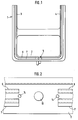
- the guide frame 1 shown in Fig. 1 consists essentially from a front frame cross part 2 and rounded over it Lateral frame parts 3 and 4 connected to corners.
- the drive device 5 is in the middle of the frame cross part 2 appropriate.
- a one-piece guide frame 1 which consists of an initially rectilinear Aluminum extruded profile is bent at the corners.
- One piece Part of the guide frame 1 are two drive cable guides 6 and 7, the cross sections of which are shown in FIGS. 9 and 11.
- the two drive cable guides run on all frame parts parallel to each other in a constant mutual Distance.
- Guide the drive cable guides 6 and 7 drive cables 8 and 9 can be moved not only in a pressure-resistant manner in corresponding channels 10 and 11, but also the rest Elements of the sunroof construction, not shown. Under The term sunroofs are all common here Understand constructions in which a roof opening assigned Cover is slidable and / or pivoted. Deviating from the embodiment shown in Fig. 1 can the guide frame is also made from individual frame parts and be
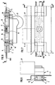
- the drive cable guides 6 and 7 on the for the installation of one in FIGS. 3 to 6 provided as a single part drive housing 12 provided Area of equal length interrupted, for example by milling the drive cable guides 6 and 7 in this area. This creates in the central region of the cross frame part 2 for the drive housing 12 an upward-facing flat mounting platform, in which there is a central passage opening 13 and two lateral mounting holes 14 are located.
- the drive housing for example injection molded from polyamide 66 12 has an elongated, approximately cuboid shape. In there are two parallel spaced guide channels, the mutual distance between them the distance between the channels 10 and 11 in the drive cable guides 6 and 7 corresponds exactly.
- the two guide channels in the drive housing 12 each have a central hollow cylindrical section 15 and both Side-matching, frustoconical end sections 16 on.
- the diameter of the central hollow cylindrical sections 15 is dimensioned so that the drive cables in these sections 8 and 9 or their helical work windings due to the wall surfaces of the hollow cylindrical sections with little Radial play are closely enclosed.
- the drive cables 8 and 9 but within the sections 15 should be slightly axial Be displaceable in the direction.
- the frustoconical end sections 16 are dimensioned so that their smallest diameter with the diameter of the central hollow cylindrical sections 15 matches, during their largest diameter at least is as large as the diameter of the channels 10 on both sides drive cable guides 6 and 7 to be connected.
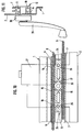
- the drive housing 12 is with a central receiving bore 17 for a flying on a cylindrical projection 18 one Gearbox 19 rotatably mounted in both directions Drive pinion 20 provided (Fig. 8).
- the location hole 17 is designed as a blind bore and perpendicular to the Guide channels 15, 16 directed.
- the diameter of the location hole 17 corresponds approximately to the distance between the center lines of the guide channels 15, 16.
- the diameter of the passage opening 13 in the cross frame part 2 agrees with the diameter of the receiving bore 17 match, so that the drive pinion 20 with sufficient radial clearance from below through the passage opening 13 are inserted into the receiving bore 17 can.
- the receiving bore 17 penetrates the middle sections 15 of the guide channels, as is particularly clear from FIG.
- the drive pinion therefore comes during assembly 20 with the helical working windings of the two drive cables 8 and 9 mesh with one another. Spins of the Drive pinion 20 lead to opposing displacement movements the drive cable.
- the two middle ones are hollow cylindrical Sections 15 of the guide channels about three times as long the tip diameter of the drive pinion 20.
- This guide length leaves the drive cables 8 and 9 practically free of side pressure out of the drive housing 12 and into the adjacent channels Enter 10 and 11 of the drive cable guides 6 and 7.
- the drive housing 12 is with respect to the drive cable guides 6 and 7 centered on the frame cross member 2 in the following manner.
- To the both ends of the drive housing 12 are step-shaped Recesses in the peripheral contour of the drive housing 12, both with respect to the transverse central axis as well as with respect to the longitudinal central axis of the drive housing 12 are arranged symmetrically.
- the step-shaped recesses are not over the full height of the drive housing 12 out, but end starting from the Mounting surface of the drive housing 12, i.e. from its lower Surface, before reaching the upper cover surface 21 of the drive housing.
- Each of the four stepped recesses is made up of one the adjacent drive cable routing assigned lateral Centering surface 22 and one the front end of the adjacent Drive cable routing associated step surface 23 formed.
- 1 and 7 to 10 is an electric motor drive shown, in which a gear motor 27 with the gear housing 19 is united.
- the drive housing 12 allows guided sliding movements with little radial play the drive cable without noise caused by joints. Due to the special design of the drive housing 12 and the cooperating gear housing 19 can be the drive device is reliable with little installation effort and attach automatically centered, with the drive cables within the drive housing 12 on the gear housing 19 located drive pinion 20 comes into mesh.
Landscapes
- Engineering & Computer Science (AREA)
- Mechanical Engineering (AREA)
- Transmission Devices (AREA)
Claims (6)
- Dispositif d'entraínement pour toits coulissants de véhicules automobiles, comportant un pignon denté d'entraínement (20) agencé en rotation dans un boítier d'entraínement (12) et en engrènement à des emplacements opposés avec des spires de travail hélicoïdales de deux câbles d'entraínement (8, 9) qui sont guidés en déplacement et de façon rigide en compression dans des canaux de guidage parallèles l'un à l'autre du boítier d'entraínement (12), les canaux de guidage étant prévus pour le branchement bilatéral en alignement de guidages de câble d'entraínement (6, 7), caractérisé en ce que les canaux de guidage (15, 16) comprennent chacun un tronçon cylindrique creux médian (15) dont la longueur correspond au moins à deux fois le diamètre du cercle de tête du pignon denté d'entraínement (20) et dont le diamètre est de telle dimension que le tronçon cylindrique creux (15) entoure étroitement avec un faible jeu radial le câble d'entraínement (8, 9), et en ce qu'au tronçon cylindrique creux médian (15) est raccordé des deux côtés un tronçon terminal respectif en forme de tronc de cône creux (16) dont le diamètre minimum coïncide avec le diamètre du tronçon cylindrique creux médian (15) et dont le diamètre maximum est au moins aussi grand que le diamètre des guidages de câble d'entraínement (6, 7) à brancher des deux côtés, le pignon denté d'entraínement (20) étant en engrènement avec les spires de travail des câbles d'entraínement (8, 9) au milieu du tronçon cylindrique creux médian (15).
- Dispositif d'entraínement selon la revendication 1, caractérisé en ce que le boítier d'entraínement (12) est pourvu d'un perçage de réception central (17) pour le pignon denté d'entraínement (20), qui est dirigé perpendiculairement aux canaux de guidage (15, 16), qui traverse ceux-ci dans la zone de l'engrènement entre les câbles d'entraínement (8, 9) et le pignon denté d'entraínement (20) et dont le diamètre correspond à la distance entre les lignes médianes des canaux de guidage (15, 16).
- Dispositif d'entraínement selon l'une ou l'autre des revendications 1 et 2, caractérisé en ce que le pignon denté d'entraínement (20) est monté en porte-à-faux sur un boítier de transmission (19) qui est vissable avec le boítier d'entraínement (12) avec interposition d'un cadre de guidage (1) comportant les guidages de câble d'entraínement (6, 7) et avec centrage des pièces reliées l'une à l'autre.
- Dispositif d'entraínement selon la revendication 3, caractérisé en ce que les guidages de câble d'entraínement (6, 7) sur le cadre de guidage (1) sont interrompus à l'emplacement du boítier d'entraínement (12), et en ce que le boítier d'entraínement (12) est susceptible d'être mis en place par coopération de formes avec des saillies de centrage (24) des deux côtés entre les guidages de câble d'entraínement (6, 7) en coiffant axialement sans jeu l'emplacement interrompu des guidages de câble d'entraínement.
- Dispositif d'entraínement selon la revendication 4, caractérisé en ce que les saillies de centrage (24) sont formées par des gradins sur le boítier d'entraínement (12), qui sont constitués chacun par une surface de centrage latérale (22) associée au guidage de câble d'entraínement (6, 7) voisin et par une surface en gradin (23) associée à l'extrémité frontale du guidage de câble d'entraínement (6, 7) voisin, les canaux de guidage (15, 16) s'étendant des deux côtés entre deux surfaces en gradin respectives (23).
- Dispositif d'entraínement selon l'une quelconque des revendications 1 à 5, caractérisé en ce que le boítier d'entraínement (12) est formé en une seule pièce par injection en matière plastique thermodurcissable résistante à l'abrasion.
Applications Claiming Priority (2)
| Application Number | Priority Date | Filing Date | Title |
|---|---|---|---|
| DE19531514A DE19531514C2 (de) | 1995-08-26 | 1995-08-26 | Antriebsvorrichtung für Schiebedächer für Kraftfahrzeuge |
| DE19531514 | 1995-08-26 |
Publications (2)
| Publication Number | Publication Date |
|---|---|
| EP0760302A1 EP0760302A1 (fr) | 1997-03-05 |
| EP0760302B1 true EP0760302B1 (fr) | 1999-04-07 |
Family
ID=7770519
Family Applications (1)
| Application Number | Title | Priority Date | Filing Date |
|---|---|---|---|
| EP96113522A Expired - Lifetime EP0760302B1 (fr) | 1995-08-26 | 1996-08-23 | Système d'entraínement pour toits coulissants de véhicules automobiles |
Country Status (5)
| Country | Link |
|---|---|
| US (1) | US5746090A (fr) |
| EP (1) | EP0760302B1 (fr) |
| JP (1) | JPH09164848A (fr) |
| DE (1) | DE19531514C2 (fr) |
| ES (1) | ES2131370T3 (fr) |
Families Citing this family (10)
| Publication number | Priority date | Publication date | Assignee | Title |
|---|---|---|---|---|
| DE19732700B4 (de) * | 1997-07-30 | 2005-07-14 | Webasto Ag | Rahmenanordnung für ein Deckelteil eines Fahrzeugdaches |
| NL1006986C2 (nl) * | 1997-09-10 | 1999-03-11 | Inalfa Ind Bv | Open-dakconstructie voor een voertuig. |
| DE10012723B4 (de) * | 2000-03-16 | 2005-03-10 | Webasto Ag Fahrzeugtechnik | Antrieb für ein verstellbares Fahrzeugteil |
| DE10059456C2 (de) * | 2000-11-30 | 2002-10-10 | Arvinmeritor Gmbh | Antriebsvorrichtung für Kraftfahrzeugschiebedächer |
| DE10203904B4 (de) * | 2002-01-31 | 2004-07-15 | Arvinmeritor Gmbh | Antriebsvorrichtung für Kraftfahrzeugschiebedächer |
| DE10327839A1 (de) | 2003-06-20 | 2005-01-05 | Arvinmeritor Gmbh | Fahrzeugdachmodul |
| US20080093509A1 (en) * | 2006-10-23 | 2008-04-24 | Union Switch & Signal, Inc. | Railroad crossing gate having a universal crossing gate arm with a rack and pinion counterweight adjustment system |
| DE102010055635A1 (de) * | 2010-12-22 | 2012-06-28 | Volkswagen Ag | Antriebseinheit, insbesondere für ein Dachöffnungssystem eines Fahrzeuges |
| JP7435077B2 (ja) * | 2020-03-13 | 2024-02-21 | 株式会社アイシン | アクチュエータ装置、サンルーフ装置、及びアクチュエータ装置の製造方法 |
| CN112758614A (zh) * | 2020-04-02 | 2021-05-07 | 苏州美梦机器有限公司 | 物料输送系统和方法 |
Family Cites Families (9)
| Publication number | Priority date | Publication date | Assignee | Title |
|---|---|---|---|---|
| GB787765A (en) * | 1955-07-13 | 1957-12-18 | Vickers Electrical Co Ltd | Improvements relating to cable devices |
| DE2135803C3 (de) * | 1971-07-17 | 1978-04-13 | Audi Nsu Auto Union Ag, 7107 Neckarsulm | Antriebsvorrichtung für Stahlkurbeldächer von Kraftfahrzeugen |
| DE2163534A1 (de) * | 1971-12-21 | 1973-06-28 | Bosch Gmbh Robert | Vorrichtung zum bewegen von einrichtungen, wie z.b. fensterscheiben, schiebedaecher, wischelementen und dergl., an kraftfahrzeugen |
| US3874722A (en) * | 1973-03-20 | 1975-04-01 | Ferro Mfg Corp | Sun roof gear box |
| DE7801538U1 (de) * | 1978-01-20 | 1978-05-03 | Webasto-Werk W. Baier Gmbh & Co, 8031 Stockdorf | Fahrzeugdach |
| DE2942006C2 (de) * | 1979-10-17 | 1987-11-12 | Rockwell Golde Gmbh, 6000 Frankfurt | Schiebedach für Kraftfahrzeuge |
| DE3803816A1 (de) * | 1988-02-09 | 1989-08-17 | Webasto Ag Fahrzeugtechnik | Vorrichtung zum antrieb von gewindekabeln |
| DE3809949A1 (de) * | 1988-03-24 | 1989-10-05 | Webasto Ag Fahrzeugtechnik | Vorrichtung zum antrieb eines drucksteif gefuehrten antriebskabels |
| DE3832681C1 (fr) * | 1988-09-27 | 1989-10-26 | Webasto Ag Fahrzeugtechnik, 8035 Gauting, De |
-
1995
- 1995-08-26 DE DE19531514A patent/DE19531514C2/de not_active Expired - Fee Related
-
1996
- 1996-08-20 US US08/704,403 patent/US5746090A/en not_active Expired - Fee Related
- 1996-08-23 EP EP96113522A patent/EP0760302B1/fr not_active Expired - Lifetime
- 1996-08-23 ES ES96113522T patent/ES2131370T3/es not_active Expired - Lifetime
- 1996-08-26 JP JP8223585A patent/JPH09164848A/ja active Pending
Also Published As
| Publication number | Publication date |
|---|---|
| EP0760302A1 (fr) | 1997-03-05 |
| US5746090A (en) | 1998-05-05 |
| DE19531514C2 (de) | 2003-11-20 |
| ES2131370T3 (es) | 1999-07-16 |
| JPH09164848A (ja) | 1997-06-24 |
| DE19531514C1 (de) | 1996-10-24 |
Similar Documents
| Publication | Publication Date | Title |
|---|---|---|
| DE4337693C2 (de) | Gehäuse für die Antriebsdrahtrolle eines Drahtzugfensterhebers | |
| EP0892724B1 (fr) | Dispositif de fixation | |
| EP0620352B1 (fr) | Elément pour transmission de force sur une porte coulissante | |
| EP0760302B1 (fr) | Système d'entraínement pour toits coulissants de véhicules automobiles | |
| EP0918671A1 (fr) | Unite d'entrainement electrique | |
| EP1291216B1 (fr) | Cadre pour un toit coulissant de véhicule ou toit levant et coulissant | |
| DE3521678C2 (fr) | ||
| EP0257500B1 (fr) | Dispositif pour diriger l'air | |
| EP1291214B1 (fr) | Cadre pour toit coulissant ou coulissant basculant pour véhicule automobile | |
| EP1747923A2 (fr) | Store à enrouler de fenêtre avec des pousées non-profilées | |
| EP0706603B1 (fr) | Leve-glace a cable | |
| EP1545269A1 (fr) | Mecanisme de commande a moteur electrique pour meubles | |
| EP1332903A2 (fr) | Dispositif d'entraínement pour toit coulissant de véhicule | |
| DE2313050C2 (de) | Vorrichtung zur Verbindung des Gewindekabels eines Kabelfensterhebers mit einer verschiebbaren Fensterscheibe, insbesondere an Kraftfahrzeugen | |
| DE60019892T2 (de) | Fensterhebevorrichtung für motorfahrzeuge | |
| DE19748594A1 (de) | Rückenlehne eines Kraftfahrzeugsitzes mit einer Kopfstütze | |
| EP0384219B1 (fr) | Dispositif d'entraînement pour une lève-glace à câble Bowden | |
| DE3136890A1 (de) | Motorbetaetigter fensterheber | |
| DE2730975C2 (de) | Kunststoffgehäuse für das Antriebsrad eines Bowdenzuges | |
| DE29522378U1 (de) | Antriebsvorrichtung für Schiebedächer für Kraftfahrzeuge | |
| WO2000008284A1 (fr) | Mecanisme de couplage destine a relier un dispositif d'immobilisation de porte a une charniere de porte de vehicule | |
| EP3919327B1 (fr) | Agencement de camera | |
| DE60318565T2 (de) | Fahrzeugdachkonstruktion und Dachreling für solch eine Dachkonstruktion | |
| EP0075268B1 (fr) | Profilé de rail de guidage avec chariot pour un appareil de commande pour porte | |
| DE3341872A1 (de) | Einrichtung zur translatorischen verschiebung eines gleitbar angeordneten teils |
Legal Events
| Date | Code | Title | Description |
|---|---|---|---|
| PUAI | Public reference made under article 153(3) epc to a published international application that has entered the european phase |
Free format text: ORIGINAL CODE: 0009012 |
|
| AK | Designated contracting states |
Kind code of ref document: A1 Designated state(s): ES FR GB IT NL SE |
|
| 17P | Request for examination filed |
Effective date: 19970212 |
|
| GRAG | Despatch of communication of intention to grant |
Free format text: ORIGINAL CODE: EPIDOS AGRA |
|
| 17Q | First examination report despatched |
Effective date: 19980423 |
|
| GRAG | Despatch of communication of intention to grant |
Free format text: ORIGINAL CODE: EPIDOS AGRA |
|
| GRAG | Despatch of communication of intention to grant |
Free format text: ORIGINAL CODE: EPIDOS AGRA |
|
| GRAH | Despatch of communication of intention to grant a patent |
Free format text: ORIGINAL CODE: EPIDOS IGRA |
|
| RAP1 | Party data changed (applicant data changed or rights of an application transferred) |
Owner name: MERITOR AUTOMOTIVE GMBH |
|
| GRAH | Despatch of communication of intention to grant a patent |
Free format text: ORIGINAL CODE: EPIDOS IGRA |
|
| GRAA | (expected) grant |
Free format text: ORIGINAL CODE: 0009210 |
|
| AK | Designated contracting states |
Kind code of ref document: B1 Designated state(s): ES FR GB IT NL SE |
|
| GBT | Gb: translation of ep patent filed (gb section 77(6)(a)/1977) |
Effective date: 19990408 |
|
| ET | Fr: translation filed | ||
| REG | Reference to a national code |
Ref country code: ES Ref legal event code: FG2A Ref document number: 2131370 Country of ref document: ES Kind code of ref document: T3 |
|
| PLBE | No opposition filed within time limit |
Free format text: ORIGINAL CODE: 0009261 |
|
| STAA | Information on the status of an ep patent application or granted ep patent |
Free format text: STATUS: NO OPPOSITION FILED WITHIN TIME LIMIT |
|
| 26N | No opposition filed | ||
| REG | Reference to a national code |
Ref country code: GB Ref legal event code: IF02 |
|
| PGFP | Annual fee paid to national office [announced via postgrant information from national office to epo] |
Ref country code: GB Payment date: 20040818 Year of fee payment: 9 |
|
| PGFP | Annual fee paid to national office [announced via postgrant information from national office to epo] |
Ref country code: SE Payment date: 20040819 Year of fee payment: 9 |
|
| PGFP | Annual fee paid to national office [announced via postgrant information from national office to epo] |
Ref country code: ES Payment date: 20040907 Year of fee payment: 9 |
|
| PG25 | Lapsed in a contracting state [announced via postgrant information from national office to epo] |
Ref country code: GB Free format text: LAPSE BECAUSE OF NON-PAYMENT OF DUE FEES Effective date: 20050823 |
|
| PG25 | Lapsed in a contracting state [announced via postgrant information from national office to epo] |
Ref country code: SE Free format text: LAPSE BECAUSE OF NON-PAYMENT OF DUE FEES Effective date: 20050824 Ref country code: ES Free format text: LAPSE BECAUSE OF NON-PAYMENT OF DUE FEES Effective date: 20050824 |
|
| EUG | Se: european patent has lapsed | ||
| GBPC | Gb: european patent ceased through non-payment of renewal fee |
Effective date: 20050823 |
|
| PGFP | Annual fee paid to national office [announced via postgrant information from national office to epo] |
Ref country code: IT Payment date: 20060831 Year of fee payment: 11 |
|
| PGFP | Annual fee paid to national office [announced via postgrant information from national office to epo] |
Ref country code: NL Payment date: 20060924 Year of fee payment: 11 |
|
| REG | Reference to a national code |
Ref country code: ES Ref legal event code: FD2A Effective date: 20050824 |
|
| PG25 | Lapsed in a contracting state [announced via postgrant information from national office to epo] |
Ref country code: NL Free format text: LAPSE BECAUSE OF NON-PAYMENT OF DUE FEES Effective date: 20080301 |
|
| NLV4 | Nl: lapsed or anulled due to non-payment of the annual fee |
Effective date: 20080301 |
|
| REG | Reference to a national code |
Ref country code: FR Ref legal event code: ST Effective date: 20080430 |
|
| PG25 | Lapsed in a contracting state [announced via postgrant information from national office to epo] |
Ref country code: FR Free format text: LAPSE BECAUSE OF NON-PAYMENT OF DUE FEES Effective date: 20070831 |
|
| PGFP | Annual fee paid to national office [announced via postgrant information from national office to epo] |
Ref country code: FR Payment date: 20060927 Year of fee payment: 11 |
|
| PG25 | Lapsed in a contracting state [announced via postgrant information from national office to epo] |
Ref country code: IT Free format text: LAPSE BECAUSE OF NON-PAYMENT OF DUE FEES Effective date: 20070823 |