EP0706697B1 - Procede d'authentification - Google Patents
Procede d'authentification Download PDFInfo
- Publication number
- EP0706697B1 EP0706697B1 EP95906972A EP95906972A EP0706697B1 EP 0706697 B1 EP0706697 B1 EP 0706697B1 EP 95906972 A EP95906972 A EP 95906972A EP 95906972 A EP95906972 A EP 95906972A EP 0706697 B1 EP0706697 B1 EP 0706697B1
- Authority
- EP
- European Patent Office
- Prior art keywords
- authentication
- pspi
- numbers
- elements
- basic
- Prior art date
- Legal status (The legal status is an assumption and is not a legal conclusion. Google has not performed a legal analysis and makes no representation as to the accuracy of the status listed.)
- Expired - Lifetime
Links
- 238000000034 method Methods 0.000 title claims abstract description 73
- 230000008569 process Effects 0.000 claims description 30
- 238000012545 processing Methods 0.000 claims description 28
- 230000000875 corresponding effect Effects 0.000 claims description 23
- 230000006870 function Effects 0.000 claims description 20
- 238000004422 calculation algorithm Methods 0.000 claims description 16
- 239000011159 matrix material Substances 0.000 claims description 16
- 230000002596 correlated effect Effects 0.000 claims description 12
- 238000004364 calculation method Methods 0.000 claims description 8
- 230000005540 biological transmission Effects 0.000 claims description 7
- 238000005516 engineering process Methods 0.000 claims description 6
- 238000012795 verification Methods 0.000 claims description 4
- 230000003993 interaction Effects 0.000 claims description 3
- 230000009471 action Effects 0.000 claims description 2
- 230000000977 initiatory effect Effects 0.000 claims description 2
- 230000000704 physical effect Effects 0.000 claims description 2
- 230000008859 change Effects 0.000 claims 1
- 238000003032 molecular docking Methods 0.000 claims 1
- 230000008054 signal transmission Effects 0.000 claims 1
- 230000000295 complement effect Effects 0.000 abstract description 13
- 230000015654 memory Effects 0.000 abstract description 9
- 230000004044 response Effects 0.000 description 14
- 238000004891 communication Methods 0.000 description 6
- 238000003860 storage Methods 0.000 description 6
- 230000036962 time dependent Effects 0.000 description 5
- 230000008901 benefit Effects 0.000 description 4
- 238000013461 design Methods 0.000 description 4
- 230000011664 signaling Effects 0.000 description 4
- 238000007792 addition Methods 0.000 description 3
- 239000000969 carrier Substances 0.000 description 3
- 230000000694 effects Effects 0.000 description 3
- 230000001747 exhibiting effect Effects 0.000 description 3
- 239000002184 metal Substances 0.000 description 3
- 238000012093 association test Methods 0.000 description 2
- 238000013475 authorization Methods 0.000 description 2
- 230000001788 irregular Effects 0.000 description 2
- 238000012986 modification Methods 0.000 description 2
- 230000004048 modification Effects 0.000 description 2
- 230000036961 partial effect Effects 0.000 description 2
- 238000003909 pattern recognition Methods 0.000 description 2
- 230000002085 persistent effect Effects 0.000 description 2
- 230000008707 rearrangement Effects 0.000 description 2
- 230000003252 repetitive effect Effects 0.000 description 2
- 239000000243 solution Substances 0.000 description 2
- 238000012360 testing method Methods 0.000 description 2
- 230000001131 transforming effect Effects 0.000 description 2
- 206010004950 Birth mark Diseases 0.000 description 1
- 101100217231 Caenorhabditis elegans asic-1 gene Proteins 0.000 description 1
- 241000282412 Homo Species 0.000 description 1
- 241001465754 Metazoa Species 0.000 description 1
- 210000004204 blood vessel Anatomy 0.000 description 1
- 210000004556 brain Anatomy 0.000 description 1
- 230000001413 cellular effect Effects 0.000 description 1
- 238000006243 chemical reaction Methods 0.000 description 1
- 238000012790 confirmation Methods 0.000 description 1
- 230000001276 controlling effect Effects 0.000 description 1
- 230000009849 deactivation Effects 0.000 description 1
- 230000001066 destructive effect Effects 0.000 description 1
- 238000009826 distribution Methods 0.000 description 1
- 210000005069 ears Anatomy 0.000 description 1
- 238000002474 experimental method Methods 0.000 description 1
- 239000012634 fragment Substances 0.000 description 1
- 210000003128 head Anatomy 0.000 description 1
- -1 ignition system Substances 0.000 description 1
- 238000002513 implantation Methods 0.000 description 1
- 238000010348 incorporation Methods 0.000 description 1
- 238000002347 injection Methods 0.000 description 1
- 239000007924 injection Substances 0.000 description 1
- 238000003780 insertion Methods 0.000 description 1
- 230000037431 insertion Effects 0.000 description 1
- 230000002452 interceptive effect Effects 0.000 description 1
- 230000007787 long-term memory Effects 0.000 description 1
- 238000004519 manufacturing process Methods 0.000 description 1
- 206010027175 memory impairment Diseases 0.000 description 1
- 230000003340 mental effect Effects 0.000 description 1
- 210000003205 muscle Anatomy 0.000 description 1
- 230000003287 optical effect Effects 0.000 description 1
- 230000005693 optoelectronics Effects 0.000 description 1
- 230000008520 organization Effects 0.000 description 1
- 230000001151 other effect Effects 0.000 description 1
- 210000001747 pupil Anatomy 0.000 description 1
- 238000012797 qualification Methods 0.000 description 1
- 210000001525 retina Anatomy 0.000 description 1
- 238000012216 screening Methods 0.000 description 1
- 230000006403 short-term memory Effects 0.000 description 1
- 239000007858 starting material Substances 0.000 description 1
- 238000012546 transfer Methods 0.000 description 1
- 210000005239 tubule Anatomy 0.000 description 1
- 230000037303 wrinkles Effects 0.000 description 1
Images


Classifications
-
- G—PHYSICS
- G07—CHECKING-DEVICES
- G07C—TIME OR ATTENDANCE REGISTERS; REGISTERING OR INDICATING THE WORKING OF MACHINES; GENERATING RANDOM NUMBERS; VOTING OR LOTTERY APPARATUS; ARRANGEMENTS, SYSTEMS OR APPARATUS FOR CHECKING NOT PROVIDED FOR ELSEWHERE
- G07C9/00—Individual registration on entry or exit
- G07C9/20—Individual registration on entry or exit involving the use of a pass
- G07C9/22—Individual registration on entry or exit involving the use of a pass in combination with an identity check of the pass holder
- G07C9/23—Individual registration on entry or exit involving the use of a pass in combination with an identity check of the pass holder by means of a password
-
- G—PHYSICS
- G07—CHECKING-DEVICES
- G07C—TIME OR ATTENDANCE REGISTERS; REGISTERING OR INDICATING THE WORKING OF MACHINES; GENERATING RANDOM NUMBERS; VOTING OR LOTTERY APPARATUS; ARRANGEMENTS, SYSTEMS OR APPARATUS FOR CHECKING NOT PROVIDED FOR ELSEWHERE
- G07C9/00—Individual registration on entry or exit
- G07C9/30—Individual registration on entry or exit not involving the use of a pass
- G07C9/32—Individual registration on entry or exit not involving the use of a pass in combination with an identity check
- G07C9/33—Individual registration on entry or exit not involving the use of a pass in combination with an identity check by means of a password
Definitions
- the purpose of this invention is to provide an easily implementable method for authenticating a person's identity, which method is viable, falsification-proof and easy to apply.
- the first type consists of equipping the person to be authenticated with a characteristic not specific to that person, for instance with a password, a microchip-card or a coded key. This characteristic is verified for authenticity by comparison with an identical or matching counterpart, checking for identity or for matching quality (lock and key system).
- a characteristic not specific to that person, for instance with a password, a microchip-card or a coded key.
- This characteristic is verified for authenticity by comparison with an identical or matching counterpart, checking for identity or for matching quality (lock and key system).
- anti-theft devices on cars can be disabled with a key containing a microchip, which exchanges a modified code with the motor control device after each use, as soon as the key is introduced into the ignition. Only if the key and car ignition match, can the car be started.
- the disadvantage of this first type of authentication method is that third parties may acquire the person non-specific characteristic illicitly in order to take on a false identity without being detected.
- the need to memorize numbers or passwords as a characteristic is often
- the second type of authentication method relies on the principle of storing certain person-specific characteristics at a place remote from the person concerned. The proof of authenticity is made by comparison of the original characteristic with the stored counterpart.
- certain physical features such as hand-geometry, finger-prints, photographs or physiological features (for example speech samples), may be used as person-specific characteristics.
- Biometrical methods are complicated, partially susceptible to falsification, and are often perceived as embarrassing by the persons concerned.
- the task of the present invention i.e. to provide an easily implementable method for authenticating a person's identity, which method is viable, falsification-proof and easy to apply, is achieved by the authentication methods defined in independent claims 1 and 2.
- associated ideas in the form of images, symbols, text or sounds which are ideas based on the individual knowledge and experiences of a person, which are sufficient for the identification of that person and which consist of associated elements or of a principal part and a complement, are defined according to an appropriate terminology as person-specific psychometrical information, abbreviated as PSPI.
- Every human being is unique because of his or her own life, that is to say his or her own experiences and knowledge. Everybody is able to form thousands of original associations which cannot be produced by another person. Specific psychometrical experiments have shown that experiences, if they are remote in time, can be remembered particularly well if they are adapted to human thought patterns, and closely connected with persons, places, times and quantities.
- the method according to the invention is methodically a self-identification, that is to say a method where the person concerned himself/herself demonstrates in the face of third parties that he/she is really a certain human being.
- Well-known didactic methods such as "interactive learning” by computer, or “multiple-choice” tests, are completely alien to the method of the invention. Those methods rely on the principle that the learner or examinee has to reproduce common knowledge and not just an individual's PSPI.
- the authentication method according to the invention is distinguished from other proposals by the possibility of using a large quantity of PSPI as an identification characteristic, if it consists of a principal part and a complement.
- PSPI benefits from the fact that it can be expressed and treated as bipartite patterns (preferably as pairs of written or spoken texts), in a particularly easy, clear and compact manner, thus with minimum investment in information units.
- the method according to the invention can be realized in a particularly economical and secure way, in distinction to the other methods.
- PSPI PSPI
- Short statements which can be apprehended at a glance are especially appropriate for representing the principal part of a PSPI, while a symbol for "true” or “false” represents the complement.
- a symbol for "true” or "false” represents the complement.
- such a statement could be: Principal part of PSPI: "Village A is located in country B”, PSPI complement: "false”.
- Such complements are amenable to being entered very easily into the system, for instance by pushing only one or two corresponding function buttons. Verification of one single statement is, however, not sufficient for safe authentication: The probability of an unauthorized person accidentally pushing the correct button is 50%. Therefore it is proposed to verify a series of different statements rather quickly one after another, and to divide the total quantity of all stored statements preferably into 50% true and 50% false ones. Thus the chance of unauthorized persons accidentally pushing the right complement buttons is minimized. For instance, if there are ten statements to be verified, the probability of an accidental authentication is only 1/2 10 or 1/1024.
- the authentication method according to the invention can be realized with existing simple and low-cost components. It has the potential of mass use in every different fields of application, such as:
- Claim 3 defines different characteristic matching schemes and arrangements of PSPI which consist of a plurality of associations of the type Ax-Bx-Cx, etc. These schemes and arrangements can be used as authentication criteria to be easily checked.
- basic numbers BZ numbers
- the basic numbers BZ are advantageously integers, and the function is preferably defined by an algorithm which delivers as result number EZ an integer having many digits. Further criteria for the choice of an appropriate algorithm are the following ones: easy implementation of the calculation, easy programming, and, finally, the impossibility of calculating the inverse function with only a limited investment of calculation and time.
- Claim 4 defines convenient technologies, system components and functional processes for realizing the authentication method according to claims 1 or 3. If a large number of persons has to be authenticated, it is advantageous to supply each of them with an individual identity card, on which are stored the surnames and first names of people who are in the first instance only known by the owner of the identity card himself/herself, as well as basic numbers attributed to these names, and the corresponding result number. The matching of the surnames and first names is advantageously performed by means of an authentication device with touch-screen, into which identity cards can be inserted. A complementary authentication on the basis of other personal characteristics can be performed in addition.
- Claims 5 and 6 define a "tele-authentication" method with a pocket-sized authentication device which allows authentication by telephone.
- a simple and falsification-proof tele-authentication can be implemented by: calculating an original result number and a new result number from a modified set of basic numbers, transmitting the original and new result numbers and basic numbers, and comparing the new result number with another one which is produced in a data processing device.
- the pocket authentication device is also suitable for all kinds of on-the-spot authentication, for storing secret codes and PINs or other personal data in an undecodable manner.
- Claim 7 points to different advantageous security measures and processing facilities of the authentication method. For instance, it is possible to program the authentication process so that new acts of authentication with new PSPI are automatically initiated at irregular intervals. By these means, the presence of a certain person can be surveyed over longer time periods. It may also be convenient to exclude the possibility of authentication temporarily or indefinitely, by means df a time switch or an external signal. For certain applications, it is advantageous to update, replace or reproduce the stored PSPI, partially or wholely, whilst observing the necessary discretion. For design reasons, the devices for the storage and processing of the PSPI have often to be placed directly at the point of interaction with the person to be authenticated.
- an actuator is a device for the generation of a distinct mechanical, electrical, optical or other effect.
- the subject of claim 8 is a miniaturized unit assembling all essential system components, having a very simple design and being easy to operate, which can be used as an electronic key in many fields of application.
- the embodiment according to claim 9 allows mutual tele-authentication of two persons who have exchanged their respective identity cards.
- Claim 10 defines another embodiment in which the PSPI of a plurality of persons is entered and stored in a central data bank, from where they are transmitted without their PSPI complements - for the purposes of authentication and if required or during certain time periods - to a decentralized control and one or more remotely operated stations having a display and an entering means for the PSPI complements.
- One advantage of this configuration is the fact that those to be authenticated do not need an identity card.
- the principle of concentrating the PSPI of a plurality of persons in a central data bank can be combined with the principle of identity cards. Authentication relies in this case on two complementary stores of PSPI, the one stored in the card possibly being relatively small and interchangeable.
- Example 1 Application of the authentication method to authorizing telecommunications.
- the task may be to exchange confidential data via fax between a person P1 at a site S1 and a person P2 at a site S2.
- Two preferably identical authentication devices, except for the stored PSPI, are placed at the sites S1 and S2.
- the device at S1 stores the PSPI of person P2, the one at S2 that of person P1.
- Both authentication devices may be connected via a digital communications network.
- Person P1 establishes contact with P2 by operating a signalling apparatus.
- the device at S2 transmits ten texts one by one from its memory to the device at S1, where P1 pushes the function button "true” or "false” after having checked each statement which appears on his/her display. After correctly identifying all statements as true or false, an actuator of the device at S2 signals the authenticity of person P1.
- P2 initiates his/her authentication. This happens in the same manner as implemented by P1, except for the fact that it is no longer necessary to operate the signalling apparatus, because the connection is already established.
- Example 2 Anti-theft device for cars.
- car theft has become a big problem. Therefore it is becoming more and more common to install anti-theft devices or immobilizers in vehicles.
- Such devices simultaneously interrupt the starter, ignition system, injection or gasoline pump, and become automatically operative within about thirty seconds after locking the car. They can only be deactivated with 1 coded card or a coded key to start the vehicle.
- Professional car thieves are, however, not discouraged by such systems: simple bridging or disconnection of the cables renders these systems. ineffective in a short time.
- traditional anti-theft devices are of no value in cases of car-jacking. The invention's embodiment redresses that situation.
- the example concerns an automobile with two miniaturized memory-units which are addressed from the same terminal.
- the first memory-unit M1 may be mounted on the gasoline pump, the second one M2 in the upper part of the vehicle body.
- the terminal T may be incorporated in the dashboard and connected with M1 and M2 via preferably multi-core cables.
- M1 may directly affect the pump by means of an actuator, thus without intermediary electrical circuitry which could be short-circuited.
- the actuator keeps the pump deactivated, the pump drive turned off, and the gasoline supply interrupted.
- the actuator keeps the gasoline pump in operation.
- M2 may act directly, or likewise by means of an actuator, on a highly visible and obtrusive signal, for instance a metal arm which, in the locking position of the actuator, is embedded in the vehicle body, so that it cannot be seen from the outside. In the operational position, the metal arm is directed upwards. In the locking position, the metal arm deactivates the vehicle mechanically. It is convenient to attach an identification mark of the vehicleowner to the arm in a clearly visible manner.
- a highly visible and obtrusive signal for instance a metal arm which, in the locking position of the actuator, is embedded in the vehicle body, so that it cannot be seen from the outside. In the operational position, the metal arm is directed upwards. In the locking position, the metal arm deactivates the vehicle mechanically. It is convenient to attach an identification mark of the vehicleowner to the arm in a clearly visible manner.
- the driver has first to switch on the electrical supply of the car, in practice by a mechanical key system. By the same operation, the components M1, M2 and T are made operational. Next, the driver operates the signalling apparatus of T and thereby establishes contact to M1. M1 transmits ten stored statement-texts one by one to T, the display of which exhibits these statements. After the appearance of each single statement, the driver pushes either of the function buttons "true” or "false". If all the statements are correctly marked (which will take about ten seconds), M1 releases its actuator and with its help the gasoline supply. In a second step, contact with M2 is established, and the signalling arm is likewise put in operational mode.
- the entire system composed of M1, M2 and T is advantageously programmed in such a way that the actuators will return to their locking positions after the expiry of certain time intervals. Further operation of the vehicle is then only possible after a new authentication.
- the time intervals are preferably fixed by a device for the generation of unpredictable random series of control pulses. In order to ensure traffic safety, some time will elapse after each turning-off impulse, until the actuators return to their locking positions.
- Example 3 Identity card with application-specific integrated circuit chip (abbreviated as ASIC) : According to Figure 1, a relatively large quantity (e.g. 100) of PSPI statements is introduced (arrows 5), observing the necessary security measures, into the identity card 1 which has a one-chip microcomputer, and each PSPI statement is stored in it, with its complement "true” or "false". A memory volume of about 1 to 10 kB is needed for this storage. For mathematical reasons, an optimum is reached if half of the total number of the introduced PSPI statements is true, and the other half false. The internal structure of the card ensures that the stored PSPI cannot be copied without authorization.
- ASIC application-specific integrated circuit chip
- the identity card can be put into an authentication de vice 2.
- a sufficient number of PSPI statements e.g. ten
- the PSPI statements without complements are transmitted electronically to a display 3 (arrow 6), where they can be viewed.
- the card owner verifies or falsifies the PSPIs one after another, by means of a push button 4 which may be supplemented by a second one.
- a push button 4 which may be supplemented by a second one.
- the PSPIs which are complemented in this way are sent back to the authentication device (arrow 7) and compared with the original PSPIs stored in the identity card (arrow 8). If this check is performed successfully, a release signal is transmitted (arrow 9). In the alternative, a stop signal is transmitted, preferably after finishing the comparison (arrow 9). In the case of a series of ten PSPI statements to be checked, the probability for a non-authorized person correctly verifying or falsifying all of the PSPI statements by chance is less than one in a thousand.
- the ASIC comprises: a long-term memory for storing the PSPI and the program routines, a microprocessor for carrying out all of the necessary operations, in particular release of the PSPI statements without their complements in an unpredictable manner, serial comparison of these PSPIs when they are complemented with the originally stored entire PSPI, generation of the release and stop signals and of the security routines, as well as a sufficient short-term memory. It is possible to transfer part of these functions to the hard- and software of the authentication device.
- Example 4 Memory-unit with actuator .
- Figure 2 shows schematically how the ASIC 1 is permanently incorporated into a fixed unit 2. This unit is equipped with a power supply 3, an electronic connection 4 to the remotely located display (which is not shown), and with an actuator 5.
- This configuration is suited to serve as an electronic anti-theft device for vehicles, especially with the inclusion of the time factor according to claim 7.
- Example 5 Active identity card.
- Figure 3 shows a miniaturized unit, such as an active identity card, which combines all of the components and functions of an authentication system.
- the casing 1 with dimensions of 10cm ⁇ 4cm ⁇ 0.8cm as an example, possesses a two-line main display 2 for viewing the PSPI without complement, the introduced complements, and other texts.
- the keyboard can be reduced to a few buttons even in the case of alphanumeric input: the button 3 (up) initiates forward- and the button 4 (down) backward-scrolling of alphanumeric characters appearing on the auxiliary display 5.
- the identity card is turned on by button 6 (on), and the first PSPI statement without complement appears on the main display 2.
- the button 7 (set) serves for the input of the relevant character into the auxiliary display, the button 8 (cancel) for cancelling incorrect inputs.
- the result of the authentication process is viewed on the main display and enables the performance of certain further operations, if it is positive.
- a miniaturized authentication device of this kind can be used in numerous applications, for instance:
- Such an electronic key can be programmed, as an example, so that codes, passwords or information chains which are stored in the device and which may be time-dependent can be sent to the lock after successful authentication, via contacts or other means not represented in Figure 3.
- the codes, passwords or information chains conform chronologically with their changing counterparts in the lock.
- the program may also initiate a temporary or permanent deactivation of the key.
- the time-dependence of the codes, passwords or information chains in key and lock can be realized in many ways.
- the digits z x of a code-number can be recalculated at regular or irregular time intervals, each digit resulting from a distinct time-dependent function which may be changed after a predetermined time interval or by signals emitted from the outside.
- the constant value a x has a different value for each digit of the code number and can itself be time-dependent. For reasons of security, it may be convenient to conceal the stored codes, passwords or information chains and their time-dependence from the key owner.
- Example 6 Authentication matrix.
- encoded electronic information is entered along one axis of a chess-board-like field via a ten-bit-wide databus.
- the encoding principle consists in a thorough-going re-arrangement of the conducting wires of the bus (the conducting wires may be numbered as LAx at the matrix input and as LEx at the matrix output).
- the following assignment is implemented in the example: LE0-LA8, LE1-LA4, LE2-LA5, LE3-LA0, LE4-LA2, LE5-LA9, LE6-LA6, LE7-LA1, LE8-LA7, LE9-LA3.
- Each one of the ten conducting wires of the databus is marked with the surname of a person.
- the information is passed on likewise via a ten-bit-wide databus.
- the ten output conducting wires are marked with the ten correlated first names of the persons, in such a way that a scrambled sequence of first names is formed, if the surnames are passed one after another.
- Each input wire can be connected with every output wire within the matrix.
- Decoding of information is implemented by re-arranging the wires in the matrix in such a way that each input wire is correctly matched with its correlated output wire, in the example: LE8-LA0, LE4-LA1, LE5-LA2, LE0-LA3, LE2-LA4, LE9-LA5, LE6-LA6, LE1-LA7, LE7-LA8, LE3-LA9.
- the hatched fields in Figure 4 indicate the combination points for correctly associated surnames and first names.
- the person to be authenticated creates the ten correct contacts between the wires of the input-bus and the output-bus, by pushing buttons or by similar action on these fields. In total, there are 10! possibilities for matching the two data-buses within the matrix. Only one of them is the correct one, and therefore suitable to decode and pass on the fed-in information.
- the principle of the authentication method described in this example and outlined in Figure 4 can be physically implemented in many ways.
- the two-dimensional pattern consisting of the ten nodal points can be used as a mechanical or electronic key which matches with a lock not recognizable from the outside.
- signs or numbers basic numbers
- the corresponding basic numbers may be fed into a calculation algorithm in order to calculate a result number which is characteristic for the pattern.
- Example 7 First Passive PIN-Card .
- the owner of the card shown first produces ten pairs of surnames (surname 0, surname 1, etc.) and associated first names (first name 0, first name 1, etc.) of persons who in principle are known only to himself/herself.
- surnames and first names with the same digit are not correlated.
- the surnames and first names are arranged on the card or on data-carriers attached to the card in such a way that pairs of surnames and first names which belong together are placed in both columns in the most random manner.
- the card owner defines (in the example) five PIN-codes (C 0, C 1, C 2, C 3, C 4), or takes note of already existing codes, each of which may contain up to ten characters.
- a digit or character (z00 to z49) of each of the five PIN-codes is compared with each first name on the card or entered into the data-carriers on the card, in five columns of digits or characters, in such a way that the first code digits or characters are placed beside that first name which belongs to the first surname, the second code digits or characters beside the first name which belongs to the second surname, and so on.
- a code has less than ten digits or characters, digits or characters of any kind are inserted after exhaustion of the store of digits or characters of the code.
- the card owner associates one after another of the surnames with the first names, and gets one by one from the relevant column the code digits or characters which are placed beside the first names.
- Example 8 Active PIN-Card .
- the surnames and first names of persons are used as associated elements Ax and Bx.
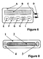
- a display B and several processing buttons are located on an electronic security card A, called here an active PIN-card.
- the following buttons may be available: E for "on/off”, F for scrolling through the code denominations, G for "okay", H for scrolling through the first names, I for exhibiting the desired entire code.
- the arrow C symbolizes the input of information to be stored: Surnames, first names, code denominations, characters or digits. The characters or digits are a function of the first names and the code denominations, the order in which the surnames are displayed depending on the code denominations.
- the identity card may be "loaded” by insertion into a loading device, by incorporation or programming of an intelligent chip, or by connecting it to a keyboard or a personal computer.
- Arrow D indicates the possibility of utilizing a code which is generated during the authentication process, for unrecognized authentication as in the case of a coded key.
- the device For the generation of a PIN, the device is switched on, and the desired code denomination is entered by scrolling and operation of the "okay" button. Thereafter, the surnames appear one after another on the display. By scrolling through the first names and operation of the "okay” button, the correct first name is entered. Simultaneously the device memorizes the correlated code digit or character or displays it in the display. The entire code is thus reproduced in a stepwise fashion.
- Example 9 Second Passive PIN-Card.
- ten text-pairs Ax-Bx composed of ideas known only to the owner, preferably surnames and first names, are inscribed on a card or sheet in two text columns in such a way that correlated surnames Ax and first names Bx are separated from each other in a highly randomized manner.
- the surnames and first names of contemporary personalities are used in Figure 7, which, of course, do not satisfy the fundamental psychometrical criterion of the invention of exclusive individual knowledge.
- indicia are arranged, preferably of letters and digits, from which eight secret codes (PIN 1 to PIN 8) can be derived.
- secret codes PIN 1 to PIN 8
- digit codes are labelled PIN 1 to PIN 5
- letter codes are labelled PIN 6 to PIN 8.
- the card owner associates the surnames with the first names (which in real cases are known only to himself/herself) one after another as indicated in the left parts of the double columns by letter or digit series, and then by following the lines of the first names comes in the right parts of the double columns to the digits or letters forming the secret code.
- Example 10 Personalized electronic key .
- a display 2 is incorporated in an elongate plastic casing 1, on which display up to about 25 characters can be exhibited in a single line.
- button 3 By pushing button 3, short statement texts are displayed one after another, in particular combinations of names, which are to be verified by the key owner, for instance by twice-repeated pushing of the button.
- an electronic signal becomes available for a short time via the contacts 4 which generate the intended effect after putting the key in a suitable electronic lock.
- the electronic circuitry of the incorporated ASIC consists essentially of a memory of about 500 to 1500 bytes and a processor for the release, display and comparison of the stored texts, as well as for the input, storage and time-dependent generation of the unlocking signal.
- a keyboard which is separate from the key, serves as an input device for the texts and, if needed, of a modified electronic signal. The key is connected to the keyboard to "load" the key. In order to activate the key effect, the key is put into a corresponding electronic lock.
- Example 11 Identity card. Fifteen text pairs (A1-B1, A2-B2, .... A15-B15), logically belonging together, are noted in two columns of the identity card according to Figure 9, correlated pairs Ax and Bx being randomly separated as far as possible. The matching of all the texts follows the scheme A1 - B1 - A2 - B2, whereby A(x+1) is placed on the same line as Bx. The first fifteen prime numbers are arranged between the two text columns as basic numbers, one after another.
- the fifteen basic numbers BZ are brought into a particular order by the above-mentioned matching scheme for the texts. In total, there are 14! ⁇ 8.7 x 10 10 different orders. It is therefore impossible to guess the order chosen for the identity card, and pointless for reasons of time and cost, to inversely calculate the order starting from the result-number. This is particularly true if one keeps the calculation algorithm secret, that is to say if one does not note it on the card.
- the identity of the card owner will be demonstrated at a given time and a given location by re-calculation of the result number EZ.
- an elementary pocket calculator is sufficient.
- a specially programmed calculator into which the fifteen basic numbers are entered one after another, and which outputs the result number directly.
- the description of the algorithm on the card can be dispensed with.
- a card reader in other words, an authentication device
- on the display of which texts and numbers are shown after introduction of the card and on which the card owner can match the texts (and numbers) on the assumption that a program contained in the reader will automatically calculate the result numbers.
- the authentication device In order to speed up the identification process in the case of institutions where a large number of people needs to be received at counters and cashdesks, for instance in banking for check-confirmation, in trading for automated debiting and for electronic cash, it is convenient to remotely locate the authentication device.
- the basic and result numbers of the identity card will be transferred by the authentication device into a short-term data-carrier (so-called electronic money) which can be evaluated by a reading device placed near the counter or the cash-desk. After a pre-determined time or if initiated by the reading process, the data temporarily entered in the data-carrier will be automatically cancelled.
- the authentication can be subdivided into two or more steps, that is to say one can perform several identifications with the same identity card or with different cards, in a time-staggered manner. For instance, it is possible to use two cards which are nearly the same and which differ only by a very small rearrangement of the texts. If somebody managed to discover the first identification process, he/she would not be successful in attempting authentication, as he/she would not be conscious of the fact that there was a second card differing from the first one.
- Example 12 Authentication with identity cards.
- each identity card contains, assembled in groups, the surnames and first names of sixteen people who are known only to the card owner. (For the sake of illustrating the principle, the surnames and first names of contemporary personages are used which, of course, do not fulfil the fundamental psychometrical criterion of the invention of exclusive individual knowledge.)
- a prime number (basic number BZ) is attributed to each name. The matching is as follows: ADENAUER-Konrad-BRECHT-Bertold-ERHARD-Ludwig, etc. Altogether there are 15! ⁇ 1.31 ⁇ 10 12 different matching possibilities.
- result number EZ ⁇ (Z x ) 2 , where Z x is defined as BZ x • BZ x+1 • BZ x+2 .
- the result number in this example is calculated to be 6 927 236 929.
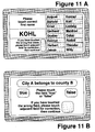
- the authentication device ( Figure 11A) displays on its touch-screen the surnames and first names as well as menu-indications.
- Figure 11B shows how an authentication device with a touch-screen already used for carrying out authentication according to the matching principle, can also be used for verifying PSPI statements, that is for authentication according to the characteristic-comparison principle.
- biometrical characteristics are used for this additional authentication, very simple features, such as height, weight, head circumference, etc., can be utilized, because it is only necessary to demonstrate that a person does or does not differ physically from another one.
- Example 13 "Tele-authentication" by telephone.
- the person to be authenticated uses an authentication device with a touch-screen and identity cards (which are not shown) with 16 surnames, 16 first names and 16 basic numbers, for instance the first 16 prime numbers from 2 to 53. If no authentication device is available, a simple card with the corresponding information which is directly readable, and a pocket calculator with a 12-digit display will suffice.
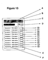
- the use of a newly shaped authentication device in the form of a small electronic calculator ( Figure 13) is, however, especially appropriate, as will be described in Example 14.
- the picture represented in Figure 12A will be displayed on the touch-screen.
- the authentication means has access to a data processing device via a terminal.
- This data processing device has a program performing the following processes: After input of a correct result number into the terminal, first the corresponding chain of basic numbers will be addressed; then a basic number will be entered into the terminal, so that - if that basic-number was correct - its corresponding basic number in the chain is identified and activated. The program then calculates the new result number automatically, according to a user-specific algorithm or on the basis of an algorithm common for all participants, from the addressed chain of basic numbers, or replaces the identified basic number by another one which was entered in the terminal.
- the display of the terminal of the authentication means is shown in Figure 12B. It has a keyboard (fields) for entering the ten basic digits, a cancellation button (field) "C” and a turning-on button (field) "on”, as well as a domain for indicating the user-led menu. Finally a field for displaying result and basic numbers, and a button (field) "okay”.
- the data processing device is programmed in such a way that each basic number of the chain can only be modified once. If after a number of acts of authentication all original basic numbers of a chain have been changed, the person to be authenticated uses a completely new set of basic numbers, either having the same matching order as another one already available in the data processing device, or generated in it at the necessary moment, and which replaces the preceding chain of basic numbers after the last modification of an original basic number.
- the telephone authentication method according to this embodiment of the invention is absolutely falsification-proof.
- the investment in communication time is minimized, because only two ten-digit and two two-digit numbers have to be transmitted.
- Example 14 Pocket authentication device. Regarding Fig ure 13, a handy authentication device composed of elementary cdmponents is described, by the use of which the person to be authenticated can perform the main steps of telephone authentication quickly and without error. This device is also suited for all kinds of on-the-spot authentication and for storing secret codes (PINs) and other personal data.
- PINs secret codes
- buttons or fields are electronically covered each by a basic number, as is shown in Figure 13. As was already mentioned in Example 12, additional basic numbers which are not shown, may be attributed to the buttons or fields in the manner described in claims 3 and 4. Further features of the device result from claim 6.
- the authentication process progresses as follows:
- the owner can exhibit possible stored secret codes (PINs) or other personal data on the display, after each successful self-authentication, with the pocket authentication device and with the help of the further features mentioned in claim 6.
- PINs stored secret codes
- the number of possible acts of tele-authentication is practically unlimited, because: first the quantity of basic numbers needed for authentication is only limited by the memory volume of the authentication device, and secondly the authentication device can be loaded with fresh data from time to time, observing certain security measures.
Landscapes
- Physics & Mathematics (AREA)
- General Physics & Mathematics (AREA)
- Collating Specific Patterns (AREA)
- Management, Administration, Business Operations System, And Electronic Commerce (AREA)
- Control Of Eletrric Generators (AREA)
- Macromolecular Compounds Obtained By Forming Nitrogen-Containing Linkages In General (AREA)
- Complex Calculations (AREA)
- Information Retrieval, Db Structures And Fs Structures Therefor (AREA)
Claims (10)
- Procédé d'authentification comprenant les étapes consistant à :
constituer une pluralité d'idées associées (informations psychométriques personnalisées) (F, figure 13) sous forme d'images, de symboles, de texte ou de sons, lesdites idées associées (informations psychométriques personnalisées) étant basées sur la connaissance et les expériences individuelles d'une personne et étant suffisantes pour l'identification de cette personne, et mémoriser lesdites idées dans un dispositif à technologie d'informations (B, figure 13), destiné à traiter les idées associées (informations psychométriques personnalisées), le dispositif comprenant un support de données fixe et portable, une puce intelligente, un moyen destiné à la saisie (D, E, figure 13), une mémorisation, une programmation, un traitement, une libération aléatoire, une comparaison, une transmission et un affichage des informations (C, figure 13) de même qu'un moyen destiné au traitement du signal et à un actionneur (5, figure 2),
caractérisé par les étapes consistant à :a) mémoriser dans le moyen de mémorisation les éléments constitutifs des informations psychométriques personnalisées dans une pluralité de groupes d'éléments (figures 3, 4, 7, 9, 10, 12) de sorte que les éléments d'un premier groupe soient placés suivant une séquence déterminée et que les éléments des groupes restants soient placés suivant une séquence aléatoire,b) ajouter des nombres (figures 5, 7, 9, 10, 13) ou des lettres aux éléments constitutifs des informations psychométriques personnalisées au moyen du dispositif,c) afficher sur le moyen d'affichage les éléments du premier groupe suivant une séquence déterminée et les éléments des groupes restant suivant une séquence aléatoire,d) réunir les éléments d'informations psychométriques personnalisées en un motif géométrique caractéristique d'informations psychométriques personnalisées reconstituées en reliant des éléments associés des groupes d'éléments respectifs,e) générer un code (figure 9, 10, 12), le code dépendant des nombres ou des lettres et de leurs positions dans le motif géométrique,f) comparer le code à un code mémorisé de façon permanente dans le dispositif. - Procédé d'authentification comprenant les étapes consistant à :
constituer une pluralité d'idées associées (informations psychométriques personnalisées) (F, figure 13) sous forme d'images, de symboles, de texte ou de sons, lesdites idées associées (informations psychométriques personnalisées) étant basées sur la connaissance et les expériences individuelles d'une personne et étant suffisantes pour l'identification de cette personne, et mémoriser lesdites idées dans un dispositif à technologie d'informations (B, figure 13), destiné à traiter les idées associées (informations psychométriques personnalisées), le dispositif comprenant un support de données fixe et portable, une puce intelligente, des moyens destinés à la saisie (D, E, figure 13), à la mémorisation, à la programmation, au traitement, à la libération aléatoire, à la comparaison, à la transmission et à l'affichage d'informations (C, figure 13) de même qu'un moyen destiné au traitement du signal et à un actionneur (5, figure 2),
caractérisé par les étapes consistant à :a) constituer une pluralité d'informations psychométriques personnalisées, chacune des informations psychométriques personnalisées étant constituée d'un énoncé et de sa valeur de vérité correspondante (vrai/faux), environ une moitié des énoncés étant vraie et l'autre moitié étant fausse,b) mémoriser les informations psychométriques personnalisées dans ledit dispositif (1, figure 1),c) afficher (3, figure 1) les énoncés l'un après l'autre suivant une séquence aléatoire sur le moyen d'affichage,d) entrer la valeur de vérité (vrai/faux) directement après l'affichage de l'énoncé correspond en poussant un ou plusieurs boutons (4, figure 1 ; 3, figure 8) du moyen de saisie (1, figure 8),e) comparer la valeur de vérité entrée à une contrepartie mémorisée dans le dispositif,f) compter le nombre des entrées correctes effectuées, après la comparaison des toutes les valeurs de vérité saisies,g) décider si l'authentification est positive suivant le nombre décompté -des entrées correctes effectuées. - Procédé d'authentification suivant la revendication 1, caractérisé en ce que les informations psychométriques personnalisées sont constituées d'une pluralité de paires associées du type Ax-Bx-Cx, etc..., et comprenant une ou plusieurs des caractéristiques suivantes :a) les paires associées des éléments Ax sont assemblées en un groupe, et l'on met en correspondance A avec x suivant une certaine séquence, les paires associées des éléments Bx sont assemblées en un autre groupe et sont associées consécutivement aux paires associées des éléments Ax par la personne devant être authentifiée, les paires associées des éléments Cx sont assemblées en un troisième groupe et sont associées consécutivement aux paires associées des éléments Ax ou Bx par la personne à authentifier, etc...,b) des signes sont attribués aux paires associées des éléments Ax, Bx, Cx, etc... ou à des parties d'entre elles, des critères d'authentification contrôlables sont formés à partir d'un processus de mise en correspondance des paires associées des éléments AX, Bx, Cx, etc..., ou à partir du processus des signes attribués,c) les paires associées des éléments Ax, Bx, Cx, etc... sont des mots ou du texte (figures 4, 5, 7, 10, 11, 12, 13),d) les paires associées des éléments Ax, Bx, Cx, etc... sont des propriétés de noms appropriées (figures 4, 5, 7, 10, 11, 12, 13), ou des nombres,e) les associations sont des associations par paires du type Ax-Bx, les paires associées des éléments Ax étant alignées le long d'un axe d'une matrice bi-dimensionnelle (figure 4), et les paires associées des éléments Bx étant alignées de façon aléatoire le long de l'autre axe de la matrice (figure 4), les points d'intersection des lignes droites tracées parallèlement aux axes passant par les repères d'alignement correspondant aux paires associées des éléments Ax, Bx définissant une séquence bi-dimensionnelle, des nombres ou des actionneurs qui génèrent un effet physique lorsque la personne à authentifier relie les éléments correspondants AX-Bx des deux axes, étant attribués aux points d'intersection des lignes droites,f) les associations sont des associations multiples du type Ax, Bx, Cx, etc ...., les textes de même catégorie A, B, C, etc... et les signes qui leur sont attribués étant agencés l'un en-dessous de l'autre en colonnes juxtaposées d'une matrice, de sorte que les éléments Ax, Bx, Cx, etc... qui sont corrélés les uns aux autres, sont répartis d'une manière aléatoire dans des colonnes de matrice différentes (Figures 5, 7, 9, 13), le processus destiné à mettre en correspondance les textes étant le suivant : on commence avec un élément A1 de la première colonne, puis on passe à un élément B1 de la seconde colonne qui est corrélé à l'élément A1, puis on passe à un élément C1 de la troisième colonne qui est corrélé à l'élément B1, et ainsi de suite, puis on passe à l'élément A2 de la première colonne qui est placé dans la même rangée de la matrice que l'élément de la dernière colonne qui a été mis en correspondance, puis on passe à l'élément B2 qui est corrélé à l'élément A2, etc..., le processus de mise en correspondance s'achevant lorsque le dernier élément de la dernière colonne a été mis en correspondance,(g) les parties alphanumériques des codes secrets et des lettres ou nombres supplémentaires ou des nombres entiers, ou des nombres premiers, ou des séries de nombres sont utilisés en tant que signes attribués (figure 5, 7),(h) des signes attribués qui sont agencés dans différentes colonnes ou séquences, sont corrélés à certains intervalles de temps ou certains processus d'authentification,(i) les signes attribués sont mémorisés dans un dispositif d'authentification, les signes ne devenant disponibles qu'après une authentification réussie,(j) les associations sont des associations multiples du type Ax, Bx, Cx, etc..., les critères d'authentification étant construits au moyen des opérations suivantes :• des nombres attribués aux éléments associés (appelés nombres "de basé") sont formés en un motif géométrique caractéristique conformément au processus de mise en correspondance des éléments associés, ou bien sont transformés en des nombres résultat caractéristiques par un calcul, chaque nombre résultat étant une fonction de toute ou partie des nombres de base et de leur agencement, ou bien de la séquence suivant laquelle les nombres de base sont introduits dans le calcul,• tous les deux ou trois nombres de base ou plus qui se suivent les uns les autres dans le processus de mise en correspondance, sont multipliés l'un avec l'autre, les produits calculés étant élevés à une puissance, les nombres ainsi produits étant ajoutés à un nombre résultat total présentant un grand nombre de chiffres,(k) les textes, nombres de base, le nombre résultat et les paramètres possibles du processus de calcul sont mémorisés dans une carte d'identité unique (1, figure 1 ; figure 10) qui est lisible par un dispositif d'authentification (2, figure 1), ou sont mémorisés dans un dispositif d'authentification miniaturisé portable (1, figure 3 ; A, figure 6 ; 1, figure 8),(l) le nombre résultat est utilisé en tant que numéro unique de la carte d'identité,(m) le dispositif d'authentification est muni d'un dispositif d'affichage (figures 11, 12), qui affiche la matrice construite à partir des textes après l'introduction de la carte d'identité dans le dispositif ou après avoir mis le dispositif en fonctionnement, le propriétaire de la carte faisant correspondre les textes au moyen de la matrice affichée, et un programme installé dans le dispositif d'authentification calculant automatiquement le nombre résultat à partir des nombres de base (figures 11A, 12A),(n) les nombres de base, le nombre résultat et autres données concernées sont automatiquement entrés dans un support de données mécanique, électronique ou magnétique à court terme intermédiaire, à partir duquel elles peuvent être évaluées pour renouveler l'authentification par un dispositif de lecture localisé à distance à l'intérieur d'un intervalle de temps déterminé, ces données étant annulées après le processus de lecture ou après que l'intervalle de temps se soit écoulé,(o) l'un des nombres de base est modifié après chaque processus d'authentification, un nouveau nombre résultat étant calculé sur cette base, le nombre résultat d'origine et le nombre de base non modifié, de même que le nombre de base modifié et le nouveau nombre résultat étant transmis à un moyen d'authentification à distance, ayant accès à un dispositif de traitement de données, ce dernier contenant sous forme électronique et protégée contre la récupération non autorisée de la chaîne ou des nombres de base mis en correspondance ensemble avec le nombre résultat d'origine et l'algorithme de calcul pour chaque participant dans le système d'authentification, après avoir entré le nombre résultat d'origine, le nombre de base d'origine et celui modifié dans le dispositif de traitement de données, le nombre de base d'origine correspondant de la chaîne mémorisée dans le dispositif est modifié et un nouveau nombre résultat est calculé et envoyé vers un dispositif d'affichage, ou bien est automatiquement comparé au nouveau nombre résultat transmis.
- Procédé d'authentification selon les revendications 1 ou 3, caractérisé par une ou plusieurs des caractéristiques suivantes :a) des cartes d'identité (figures 10) qui contiennent une pluralité de noms et des prénoms associés, des nombres de base (figure 10) qui leur sont attribués, et le nombre résultat calculé à partir des ces nombres de base (figure 10),b) un dispositif de traitement de données fixe qui contient des informations psychométriques personnalisées ou des données biométriques supplémentaires concernant les personnes participant au système d'authentification,c) un dispositif d'authentification avec un écran ou un écran sensitif (figure 11A) qui affiche, après l'introduction d'une carte d'identité, tout ou partie des prénoms et consécutivement un nom à la fois, ou plusieurs simultanément ou la totalité des noms, et qui en outre affiche les parties principales des informations psychométriques personnalisées supplémentaires qui sont transmises à partir du dispositif de traitement de données fixe, et d'autres informations,d) un moyen inter-actif, par exemple un clavier ou un crayon d'écran sensitif destiné à mettre en correspondance les noms affichés avec les prénoms et à vérifier ou à compléter les parties principales des informations psychométriques personnalisées affichées,e) des circuits et un logiciel destinés à mettre en oeuvre les fonctions d'authentification, par exemple en affichant les noms, les prénoms, les parties principales des informations psychométriques personnalisées et d'autres données sur l'écran, en mettant en correspondance les noms avec les prénoms, en traitant les nombres, en effectuant la vérification des énoncés, la comparaison des données avec leur contre-parties mémorisées, la libération d'un signal de résultat,f) un dispositif d'authentification avec un écran sensitif, comprenant une ou plusieurs des caractéristiques suivantes :• la personne à authentifier touche le prénom corrélé après l'affichage de chaque nom,• le toucher d'un prénom erroné est annulé en touchant une zone d'annulation,• chaque nom successif est affiché après avoir touché un prénom,• après la mise en correspondance de tous les noms et les prénoms, le dispositif d'authentification calcule un nombre résultat à partir de la chaîne ou des nombres de base correspondants, et signale que l'authentification est réussie, si le nombre résultat calculé coïncide avec le nombre résultat mémorisé dans la carte d'identité.
- Procédé d'authentification selon l'une quelconque des revendications 1, 3 et 4, caractérisé en ce qu'un nombre résultat d'origine, et un nouveau nombre résultat calculé à partir d'un ensemble modifié des nombres de base, sont calculés et transmis, complètement ou partiellement, pour une comparaison avec des nombres résultat correspondants produits dans un dispositif de traitement de données.
- Procédé d'authentification selon l'une quelconque des revendications 1, 3, 4 et 5, caractérisé par un dispositif d'authentification comprenant tout ou partie des caractéristiques suivantes :(a) un boîtier tel que celui d'un petit calculateur de poche électronique plat (B, figure 13),(b) une carte d'identité électroniquement active présentant le format d'une carte de crédit (A, figure 6),(c) un dispositif d'affichage (B, figure 6 ; C, figure 13) destiné à afficher des nombres et/ou des lettres,(d) une alimentation en énergie photovoltaïque ou galvanique (A, figure 13),(e) un ou plusieurs boutons destiné à une commutation sur le dispositif d'authentification et à initier des fonctions supplémentaires (D, figure 13),(f) une zone d'affichage destinée à des mots qui sont agencés en deux colonnes (F, figure 13) et qui sont générés par une écriture, optique ou électronique,(g) un couvercle transparent destiné à la zone d'affichage, sous lequel couvercle, une carte en deux colonnes destinée à afficher des mots est placée en permanence ou de façon inter-changeable,(h) des boutons poussoir ou des zones d'écran sensitif (E, figure 13), qui sont placés suivant une colonne correspondant aux colonnes de mots, étant actionnés de façon consécutive par la personne à authentifier conformément au processus de mise en correspondance des mots, et de sorte que chaque actionnement libère un nombre de base prédéterminé pour les calculs dans le dispositif d'authentification,(i) l'inscription de toute combinaison quelconque des nombres 0 à 9 et/ou des lettres sur les boutons ou les zones,(k) des fonctions électroniques exécutant tout ou partie des processus suivants :• l'attribution d'un ou plusieurs nombres de base à chaque bouton ou zone, des nombres de base suivants n'étant activés qu'après que les nombres de base attribués initialement de tous les boutons ou zones aient été changés,• l'affichage du dernier nombre résultat calculé,• le calcul et l'affichage d'un nouveau nombre résultat sur la base des nombres de base libérés,• la génération de nombres par des processus tels que : l'actionnement de boutons ou de zones sur lesquels des nombres sont inscrits, par le défilement d'une série de nombres sur le dispositif d'affichage et l'arrêt du processus de défilement lorsque le nombre désiré apparaît, la génération de nombres aléatoires,• l'attribution de nombres aux boutons ou aux zones destinés à servir de nombres de base, ou à être mémorisés en tant que code secret (numéro d'identification personnel),• la génération de lettres par l'actionnement de boutons ou de zones comportant des inscriptions de lettres,• l'affichage des informations mémorisées après une authentification réussie,• le verrouillage des processus suivants après des tentatives invalides, non réussies ou inadmissibles lors de l'authentification : l'actionnement du dispositif d'authentification, l'affichage de mots, l'affichage de nombres et de lettres, la modification des nombres de base à attribuer aux boutons ou aux zones.
- Procédé d'authentification selon l'une quelconque des revendications précédentes, caractérisé par une ou plusieurs des caractéristiques suivantes :(a) un élément d'informations psychométriques personnalisées suivant n'est émis qu'après que le traitement des informations psychométriques personnalisées précédentes ait été achevé,(b) un actionneur (5, figure 2) est activé automatiquement ou par un signal appliqué de l'extérieur, après une authentification réussie,(c) des processus d'authentification renouvelés sont initiés automatiquement ou par une action externe sur le dispositif d'authentification, sur la base d'autres informations psychométriques personnalisées, après certains intervalles de temps,(d) des informations psychométriques personnalisées mémorisées sont partiellement ou totalement remplaçables ou reproductibles, suivant certaines mesures de sécurité.
- Procédé d'authentification sélon l'une quelconque des revendications précédentes, caractérisé en ce que tous les composants essentiels du dispositif sont assemblés en une seule unité miniaturisée telle qu'une clé électronique (1, figure 3 ; A, figure 6 ; 1, figure 8), dont le boîtier est au moins muni de :(a) un dispositif d'affichage (3, figure 1 ; B, figure 6 ; 2, figure 8) destiné à afficher les éléments d'informations psychométriques personnalisées,(b) un bouton destiné à rappeler, vérifier ou falsifier, et annuler du texte sur le dispositif d'affichage (3, figure 8),(c) une zone de stockage (4, figure 8) destinée à la transmission d'un signal à partir de l'unité pendant un intervalle de temps après une authentification réussie.
- Procédé d'authentification selon l'une quelconque des revendications précédentes, caractérisé en ce que dans le but de l'authentification d'une liaison de télécommunication, le dispositif d'affichage et le dispositif destiné à saisir les compléments d'informations psychométriques personnalisées 1 est situé sur un site S1 d'une personne P1, et est relié par l'intermédiaire d'une liaison de télécommunication au dispositif d'affichage et au dispositif destiné à saisir des compléments d'informations psychométriques personnalisées 2 d'une personne P2 au niveau d'un site S2, la personne P2 saisissant la carte d'identité d'une personne P1 et pour une authentification inverse, la personne P1 saisissant la carte d'identité d'une personne P2.
- Procédé d'authentification selon l'une quelconque des revendications précédentes, caractérisé par une ou les deux des caractéristiques suivantes :(a) les informations psychométriques personnalisées d'une pluralité de personnes sont entrées et mémorisées dans une banque de données centrale, à partir de laquelle elles sont transmises sans leurs compléments d'informations psychométriques personnalisées, pour une authentification et sur demande de la personne à authentifier ou pendant certains intervalles de temps, vers une commande décentralisée et un ou plusieurs postes actionnés à distance, chacun étant équipé d'un moyen d'affichage et d'un moyen de saisie pour les compléments d'informations psychométriques personnalisées,(b) des informations psychométriques personnalisées supplémentaires sont disponibles sur des cartes d'identité individuelles en plus des informations psychométriques personnalisées mémorisées dans la banque de données centrale, l'authentification étant réalisée au niveau des postes décentralisés sur la base à la fois des deux mémoires d'informations psychométriques personnalisées.
Applications Claiming Priority (15)
| Application Number | Priority Date | Filing Date | Title |
|---|---|---|---|
| DE4402430A DE4402430A1 (de) | 1994-01-27 | 1994-01-27 | Authentisierer |
| DE4402430 | 1994-01-27 | ||
| DE4416665 | 1994-05-11 | ||
| DE4416665A DE4416665A1 (de) | 1994-01-27 | 1994-05-11 | Psychometrischer Authentisierer |
| DE4419882 | 1994-06-07 | ||
| DE4419882A DE4419882A1 (de) | 1994-01-27 | 1994-06-07 | Psychometrisches Authentisierverfahren |
| DE4423415 | 1994-07-05 | ||
| DE4423415A DE4423415A1 (de) | 1994-01-27 | 1994-07-05 | Psychometrischer Authentisierer |
| DE4430368 | 1994-08-26 | ||
| DE4430368A DE4430368A1 (de) | 1994-01-27 | 1994-08-26 | Identitätskarte |
| DE4436340 | 1994-10-11 | ||
| DE4436340A DE4436340A1 (de) | 1994-01-27 | 1994-10-11 | Authentisierverfahren mit Authentkarten |
| DE4443039 | 1994-12-04 | ||
| DE4443039A DE4443039A1 (de) | 1994-01-27 | 1994-12-04 | Authentisierverfahren |
| PCT/EP1995/000178 WO1995020802A1 (fr) | 1994-01-27 | 1995-01-19 | Procede d'authentification |
Publications (2)
| Publication Number | Publication Date |
|---|---|
| EP0706697A1 EP0706697A1 (fr) | 1996-04-17 |
| EP0706697B1 true EP0706697B1 (fr) | 1997-04-23 |
Family
ID=27561591
Family Applications (1)
| Application Number | Title | Priority Date | Filing Date |
|---|---|---|---|
| EP95906972A Expired - Lifetime EP0706697B1 (fr) | 1994-01-27 | 1995-01-19 | Procede d'authentification |
Country Status (8)
| Country | Link |
|---|---|
| US (1) | US5821871A (fr) |
| EP (1) | EP0706697B1 (fr) |
| AT (1) | ATE152270T1 (fr) |
| CA (1) | CA2180031A1 (fr) |
| DK (1) | DK0706697T3 (fr) |
| ES (1) | ES2101607T3 (fr) |
| GR (1) | GR3023591T3 (fr) |
| WO (1) | WO1995020802A1 (fr) |
Families Citing this family (40)
| Publication number | Priority date | Publication date | Assignee | Title |
|---|---|---|---|---|
| EP0763802A3 (fr) * | 1995-09-19 | 1997-05-21 | Sc Info & Inno Technologie Inf | Procédé d'authentication psychométrique |
| US6542583B1 (en) * | 1997-03-06 | 2003-04-01 | Avaya Technology Corp. | Caller identification verification system |
| FR2770919B1 (fr) | 1997-11-12 | 2000-11-10 | Antoine Roger Pierre Lebard | Procede d'interpretation individuelle et comparative de donnees, et systeme de mise en oeuvre |
| US20050114705A1 (en) * | 1997-12-11 | 2005-05-26 | Eran Reshef | Method and system for discriminating a human action from a computerized action |
| DE19820484C1 (de) * | 1998-05-07 | 1999-11-18 | Sc Info & Inno Gmbh & Co | Verfahren zur Prüfung der Unversehrtheit und der Echtheit eines Textes |
| US7305562B1 (en) | 1999-03-09 | 2007-12-04 | Citibank, N.A. | System, method and computer program product for an authentication management infrastructure |
| US6256737B1 (en) | 1999-03-09 | 2001-07-03 | Bionetrix Systems Corporation | System, method and computer program product for allowing access to enterprise resources using biometric devices |
| WO2000072501A1 (fr) | 1999-05-22 | 2000-11-30 | Sc-Info+Inno Gmbh+Co. | Transmission et authentification automatiques de textes |
| JP2001023300A (ja) * | 1999-07-09 | 2001-01-26 | Fujitsu Ltd | 記憶装置、記録媒体のアクセス制御装置および記録媒体のアクセス制御方法 |
| US8473452B1 (en) | 1999-09-20 | 2013-06-25 | Ims Health Incorporated | System and method for analyzing de-identified health care data |
| US6732113B1 (en) * | 1999-09-20 | 2004-05-04 | Verispan, L.L.C. | System and method for generating de-identified health care data |
| EP1134703A1 (fr) * | 2000-03-14 | 2001-09-19 | BRITISH TELECOMMUNICATIONS public limited company | Services sécurisés |
| US7441263B1 (en) | 2000-03-23 | 2008-10-21 | Citibank, N.A. | System, method and computer program product for providing unified authentication services for online applications |
| JP3416626B2 (ja) * | 2000-07-31 | 2003-06-16 | 松下電器産業株式会社 | 識別情報入力装置 |
| US20020196963A1 (en) * | 2001-02-23 | 2002-12-26 | Biometric Security Card, Inc. | Biometric identification system using a magnetic stripe and associated methods |
| US6806869B2 (en) * | 2001-03-02 | 2004-10-19 | Seiko Epson Corporation | Data processing system utilizing discrete operating device |
| US20040199475A1 (en) * | 2001-04-27 | 2004-10-07 | Rivest Ronald L. | Method and system for micropayment transactions |
| WO2003022647A1 (fr) * | 2001-09-11 | 2003-03-20 | Kevin Orton | Systeme et procede de securite de vol d'aeronefs |
| US20040003260A1 (en) * | 2002-06-27 | 2004-01-01 | Philip Hawkes | System and method for audio tickets |
| US7734929B2 (en) * | 2004-04-30 | 2010-06-08 | Hewlett-Packard Development Company, L.P. | Authorization method |
| WO2006042212A2 (fr) * | 2004-10-08 | 2006-04-20 | Proximities, Inc. | Procede pour autoriser un compte auxiliaire au moyen de bracelets d'identification |
| GB2434472A (en) * | 2005-12-01 | 2007-07-25 | Jonathan Geoffrey Milt Craymer | Verification using one-time transaction codes |
| US9817963B2 (en) * | 2006-04-10 | 2017-11-14 | International Business Machines Corporation | User-touchscreen interaction analysis authentication system |
| CN101496344B (zh) * | 2006-07-20 | 2014-08-20 | 黄金富 | 网上银钱支付和身份确认的带自设认证算式的方法和系统 |
| US20080094220A1 (en) * | 2006-10-19 | 2008-04-24 | Joseph Foley | Methods and Systems for Improving RFID Security |
| US9355273B2 (en) * | 2006-12-18 | 2016-05-31 | Bank Of America, N.A., As Collateral Agent | System and method for the protection and de-identification of health care data |
| US20100114607A1 (en) * | 2008-11-04 | 2010-05-06 | Sdi Health Llc | Method and system for providing reports and segmentation of physician activities |
| ITTO20090035A1 (it) * | 2009-01-20 | 2010-07-21 | Ireth S R L | Procedimento per l'autenticazione di utenti/clienti |
| US9141758B2 (en) * | 2009-02-20 | 2015-09-22 | Ims Health Incorporated | System and method for encrypting provider identifiers on medical service claim transactions |
| US20130006479A1 (en) * | 2009-07-30 | 2013-01-03 | Anderson Gerald G | Microchip System and Method for Operating a Locking Mechanism and for Cashless Transactions |
| CN102104484A (zh) * | 2009-12-22 | 2011-06-22 | 鸿富锦精密工业(深圳)有限公司 | 电子设备及密码保护方法 |
| US8380995B1 (en) * | 2011-11-29 | 2013-02-19 | Google Inc. | Process for login of a computing device with a touchscreen |
| US8522310B1 (en) * | 2012-01-05 | 2013-08-27 | TidePool, Inc. | Psychometric keycard for online applications |
| US10096383B2 (en) * | 2015-11-24 | 2018-10-09 | International Business Machines Corporation | Performing a health analysis using a smart floor mat |
| CN113066215B (zh) * | 2021-03-15 | 2022-09-13 | 长沙广缘物业管理有限公司 | 一种二维码门禁管理方法、系统、以及存储介质 |
| US12499029B2 (en) | 2023-03-27 | 2025-12-16 | Dell Products L.P. | System and method for use based management of diagnostic data |
| US12505248B2 (en) | 2023-04-27 | 2025-12-23 | Dell Products L.P. | System and method for managing access control of data across a distributed system |
| US12536182B2 (en) | 2023-08-30 | 2026-01-27 | Dell Products L.P. | System and method for managing data by processing search queries |
| US12524560B2 (en) * | 2023-08-30 | 2026-01-13 | Dell Products L.P. | Multifactor authentication based on user experiences |
| US12481781B2 (en) | 2023-08-30 | 2025-11-25 | Dell Products L.P. | System and method for managing access to data stored in a data management system |
Family Cites Families (41)
| Publication number | Priority date | Publication date | Assignee | Title |
|---|---|---|---|---|
| DE683233C (de) * | 1936-05-03 | 1939-11-02 | Arthur Haupt | Einrichtung zum Messen der Abweichungen des Abstandes zweier Punkte von einem vorgeschriebenen Wert, insbesondere zum Vergleich von Handschriften |
| DE1762669U (de) * | 1958-01-04 | 1958-03-06 | Nista Stahlmoebel Und Geraeteb | Unterboden fuer matratzenauflage. |
| DE1084036B (de) * | 1959-11-03 | 1960-06-23 | Townsend Company | Verfahren und Vorrichtung zum Herstellen von Erkennungsbildern von Personen |
| DE1195057B (de) * | 1962-09-05 | 1965-06-16 | Moritz J Furtmayr | Personenfeststellungskartei |
| US3774227A (en) * | 1971-05-20 | 1973-11-20 | Veeder Industries Inc | Multiple-key lock mechanism |
| BE790510A (fr) * | 1971-11-04 | 1973-02-15 | Rothfjell Rolf E | Procede pour l'identification de personnes en utilisant des courbes caracteristiques selectionnees du corps |
| DE2846974C2 (de) * | 1976-06-01 | 1987-05-07 | Horst 2000 Hamburg Mau | Vorrichtung zur Festellung der Identität einer Person |
| US4202626A (en) * | 1978-02-24 | 1980-05-13 | A Patent Partnership | Signature verification and authentication systems |
| US4223403A (en) * | 1978-06-30 | 1980-09-16 | International Business Machines Corporation | Cryptographic architecture for use with a high security personal identification system |
| GB2058417B (en) * | 1979-06-25 | 1983-02-02 | Gao Ges Automation Org | Input of a personal code word |
| US4295039A (en) * | 1979-12-03 | 1981-10-13 | International Business Machines Corporation | Method and apparatus for achieving secure password verification |
| AU540481B2 (en) * | 1980-02-14 | 1984-11-22 | Hermann Stockburger | Authorization card |
| SE425704B (sv) * | 1981-03-18 | 1982-10-25 | Loefberg Bo | Databerare |
| US4449189A (en) * | 1981-11-20 | 1984-05-15 | Siemens Corporation | Personal access control system using speech and face recognition |
| GB2112190B (en) * | 1981-12-23 | 1985-12-18 | Omron Tateisi Electronics Co | Personal identification system |
| DE3301629A1 (de) * | 1983-01-19 | 1984-07-19 | ITALTEL Società Italiana Telecomunicazioni S.p.A., Milano | Schaltungsanordnung zum identifizieren und klassifizieren von teilnehmern |
| JPS629470A (ja) * | 1985-07-05 | 1987-01-17 | Casio Comput Co Ltd | 個人証明カ−ドにおける本人照合方式 |
| DE3827172A1 (de) * | 1987-08-13 | 1989-03-16 | Peter Elsner | Einrichtung zur identifizierung von nachrichten |
| DE3880695T2 (de) * | 1987-10-02 | 1993-09-23 | Daya Ranjit Senanayake | System und verfahren zur persoenlichen identifizierung. |
| DE3834048A1 (de) * | 1988-10-06 | 1990-04-12 | Karl Lambert Gohlke | Verfahren zur optoelektronischen identifikation einer person |
| DE3834046A1 (de) * | 1988-10-06 | 1990-04-12 | Karl Lambert Gohlke | Verfahren und vorrichtung zum begrenzen des zugangs zu bestimmten datenbereichen eines rechners |
| GB8902639D0 (en) * | 1989-02-07 | 1989-03-30 | Burkill Vance | Memory aid |
| KR930005570B1 (ko) * | 1989-11-13 | 1993-06-23 | 주식회사 금성사 | 홀로그램(hologram)을 이용한 지문인식장치 |
| US5037301A (en) * | 1989-11-17 | 1991-08-06 | Dentistry Researchers & Designers Inc. | Method enabling dental identification of humans and animals |
| DE3943097A1 (de) * | 1989-12-27 | 1991-07-11 | Wilhelm Anton Jakobus | Verfahren zum auffinden von gespeicherten medizinischer daten eines lebewesens mit hilfe eines suchbegriffes, dadurch gekennzeichnet, dass dieser suchbegriff biometrisch messbare daten sind |
| DE4005448A1 (de) * | 1990-02-21 | 1991-08-22 | Jaroschinsky Achim | Verfahren und vorrichtung zum abgleichen zweier datengruppen |
| EP0444351A3 (en) * | 1990-02-28 | 1992-05-27 | American Telephone And Telegraph Company | Voice password-controlled computer security system |
| DE4008971A1 (de) * | 1990-03-20 | 1991-09-26 | Siemens Nixdorf Inf Syst | Verfahren zur authentifizierung eines eine datenstation benutzenden anwenders |
| DE4009051A1 (de) * | 1990-03-21 | 1991-09-26 | Diehl Gmbh & Co | Biometrisches identifizierungs- und zugangs-kontrollsystem |
| US5313564A (en) * | 1990-07-11 | 1994-05-17 | Fontech Ltd. | Graphic matter and process and apparatus for producing, transmitting and reading the same |
| DE4039648A1 (de) * | 1990-12-12 | 1992-07-16 | Rolf Wendler | Messwertverarbeitungssystem fuer ein biologisches objekt |
| EP0574434B1 (fr) * | 1991-03-06 | 1995-07-26 | Süddeutsche Feinmechanik Gmbh | Canule pour l'insertion d'un element |
| DE4107042C2 (de) * | 1991-03-06 | 1994-07-07 | Sueddeutsche Feinmechanik | Kanüle zum Implantieren von insbesondere zum Identifizieren von Lebewesen bestimmten Identifikationsträgern |
| JPH052635A (ja) * | 1991-06-26 | 1993-01-08 | Chuo Spring Co Ltd | 個人識別装置 |
| JP2671649B2 (ja) * | 1991-07-08 | 1997-10-29 | 三菱電機株式会社 | 認証方式 |
| US5204902A (en) * | 1991-09-13 | 1993-04-20 | At&T Bell Laboratories | Cellular telephony authentication arrangement |
| ATE153202T1 (de) * | 1991-10-31 | 1997-05-15 | Kwang Sil Lee | Elektronisches identifizierungssystem mit automatischer fernantwort und identifizierungsverfahren hierzu |
| DE4142964C2 (de) * | 1991-12-24 | 2003-05-08 | Gao Ges Automation Org | Datenaustauschsystem mit Überprüfung der Vorrichtung auf Authentisierungsstatus |
| US5276314A (en) * | 1992-04-03 | 1994-01-04 | International Business Machines Corporation | Identity verification system resistant to compromise by observation of its use |
| GB9211648D0 (en) * | 1992-06-02 | 1992-07-15 | Racal Datacom Ltd | Data communication system |
| US5327497A (en) * | 1992-06-04 | 1994-07-05 | Integrated Technologies Of America, Inc. | Preboot protection of unauthorized use of programs and data with a card reader interface |
-
1995
- 1995-01-19 EP EP95906972A patent/EP0706697B1/fr not_active Expired - Lifetime
- 1995-01-19 WO PCT/EP1995/000178 patent/WO1995020802A1/fr not_active Ceased
- 1995-01-19 US US08/682,524 patent/US5821871A/en not_active Expired - Fee Related
- 1995-01-19 ES ES95906972T patent/ES2101607T3/es not_active Expired - Lifetime
- 1995-01-19 CA CA002180031A patent/CA2180031A1/fr not_active Abandoned
- 1995-01-19 AT AT95906972T patent/ATE152270T1/de not_active IP Right Cessation
- 1995-01-19 DK DK95906972.5T patent/DK0706697T3/da active
-
1997
- 1997-05-30 GR GR970401234T patent/GR3023591T3/el unknown
Also Published As
| Publication number | Publication date |
|---|---|
| WO1995020802A1 (fr) | 1995-08-03 |
| ES2101607T3 (es) | 1997-07-01 |
| GR3023591T3 (en) | 1997-08-29 |
| DK0706697T3 (da) | 1997-05-26 |
| ATE152270T1 (de) | 1997-05-15 |
| US5821871A (en) | 1998-10-13 |
| CA2180031A1 (fr) | 1995-08-03 |
| EP0706697A1 (fr) | 1996-04-17 |
Similar Documents
| Publication | Publication Date | Title |
|---|---|---|
| EP0706697B1 (fr) | Procede d'authentification | |
| EP0614559B1 (fr) | Dispositifs d'identification de personnes et systemes de commande d'acces | |
| US7036730B2 (en) | Electronic voting apparatus, system and method | |
| US5457747A (en) | Anti-fraud verification system using a data card | |
| US7431209B2 (en) | Electronic voting apparatus, system and method | |
| US5056141A (en) | Method and apparatus for the identification of personnel | |
| US5239583A (en) | Method and apparatus for improved security using access codes | |
| AU2006321402B2 (en) | A method and apparatus for verifying a person's identity or entitlement using one-time transaction codes | |
| US7461787B2 (en) | Electronic voting apparatus, system and method | |
| US5130519A (en) | Portable pin card | |
| US20010034640A1 (en) | Physical and digital secret ballot systems | |
| US20030112120A1 (en) | System & method for biometric-based fraud protection | |
| CA2220414A1 (fr) | Systeme et procede d'identification formelle | |
| JPH06507277A (ja) | 個人認証方法および装置 | |
| US5636271A (en) | Security code selector for telephone access card | |
| JP3959913B2 (ja) | 入退場管理システム及び本人確認方法 | |
| US20110113487A1 (en) | Icon card verification system | |
| JPH025195A (ja) | Icカード | |
| JPH11167553A (ja) | オンラインシステムでの本人確認システム | |
| DE69500258T2 (de) | Authentifizierungsverfahren | |
| JP7620230B2 (ja) | 割符機能付ラベル | |
| JP3745245B2 (ja) | 本人確認装置および本人確認方法 | |
| JPS62190583A (ja) | 登録カ−ドを用いた個人識別システム | |
| JPH04205245A (ja) | 個人識別装置 | |
| DE4402430A1 (de) | Authentisierer |
Legal Events
| Date | Code | Title | Description |
|---|---|---|---|
| PUAI | Public reference made under article 153(3) epc to a published international application that has entered the european phase |
Free format text: ORIGINAL CODE: 0009012 |
|
| 17P | Request for examination filed |
Effective date: 19960118 |
|
| AK | Designated contracting states |
Kind code of ref document: A1 Designated state(s): AT BE CH DE DK ES FR GB GR IE IT LI NL PT SE |
|
| GRAG | Despatch of communication of intention to grant |
Free format text: ORIGINAL CODE: EPIDOS AGRA |
|
| 17Q | First examination report despatched |
Effective date: 19960424 |
|
| GRAH | Despatch of communication of intention to grant a patent |
Free format text: ORIGINAL CODE: EPIDOS IGRA |
|
| ITF | It: translation for a ep patent filed | ||
| GRAH | Despatch of communication of intention to grant a patent |
Free format text: ORIGINAL CODE: EPIDOS IGRA |
|
| GRAA | (expected) grant |
Free format text: ORIGINAL CODE: 0009210 |
|
| AK | Designated contracting states |
Kind code of ref document: B1 Designated state(s): AT BE CH DE DK ES FR GB GR IE IT LI NL PT SE |
|
| REF | Corresponds to: |
Ref document number: 152270 Country of ref document: AT Date of ref document: 19970515 Kind code of ref document: T |
|
| REG | Reference to a national code |
Ref country code: CH Ref legal event code: NV Representative=s name: BUECHEL & PARTNER AG PATENTBUERO Ref country code: CH Ref legal event code: EP |
|
| REG | Reference to a national code |
Ref country code: DK Ref legal event code: T3 |
|
| REF | Corresponds to: |
Ref document number: 69500258 Country of ref document: DE Date of ref document: 19970528 |
|
| REG | Reference to a national code |
Ref country code: ES Ref legal event code: FG2A Ref document number: 2101607 Country of ref document: ES Kind code of ref document: T3 |
|
| ET | Fr: translation filed | ||
| REG | Reference to a national code |
Ref country code: IE Ref legal event code: FG4D Free format text: 73626 |
|
| REG | Reference to a national code |
Ref country code: GR Ref legal event code: FG4A Free format text: 3023591 |
|
| PLBE | No opposition filed within time limit |
Free format text: ORIGINAL CODE: 0009261 |
|
| STAA | Information on the status of an ep patent application or granted ep patent |
Free format text: STATUS: NO OPPOSITION FILED WITHIN TIME LIMIT |
|
| 26N | No opposition filed | ||
| PGFP | Annual fee paid to national office [announced via postgrant information from national office to epo] |
Ref country code: PT Payment date: 19990106 Year of fee payment: 5 |
|
| PGFP | Annual fee paid to national office [announced via postgrant information from national office to epo] |
Ref country code: DK Payment date: 19990122 Year of fee payment: 5 |
|
| PGFP | Annual fee paid to national office [announced via postgrant information from national office to epo] |
Ref country code: IE Payment date: 19990127 Year of fee payment: 5 |
|
| PGFP | Annual fee paid to national office [announced via postgrant information from national office to epo] |
Ref country code: NL Payment date: 19990129 Year of fee payment: 5 Ref country code: AT Payment date: 19990129 Year of fee payment: 5 |
|
| PGFP | Annual fee paid to national office [announced via postgrant information from national office to epo] |
Ref country code: GR Payment date: 19990201 Year of fee payment: 5 Ref country code: CH Payment date: 19990201 Year of fee payment: 5 |
|
| PG25 | Lapsed in a contracting state [announced via postgrant information from national office to epo] |
Ref country code: IE Free format text: LAPSE BECAUSE OF NON-PAYMENT OF DUE FEES Effective date: 20000119 Ref country code: DK Free format text: LAPSE BECAUSE OF NON-PAYMENT OF DUE FEES Effective date: 20000119 Ref country code: AT Free format text: LAPSE BECAUSE OF NON-PAYMENT OF DUE FEES Effective date: 20000119 |
|
| PG25 | Lapsed in a contracting state [announced via postgrant information from national office to epo] |
Ref country code: LI Free format text: LAPSE BECAUSE OF NON-PAYMENT OF DUE FEES Effective date: 20000131 Ref country code: GR Free format text: LAPSE BECAUSE OF NON-PAYMENT OF DUE FEES Effective date: 20000131 Ref country code: CH Free format text: LAPSE BECAUSE OF NON-PAYMENT OF DUE FEES Effective date: 20000131 |
|
| PG25 | Lapsed in a contracting state [announced via postgrant information from national office to epo] |
Ref country code: PT Free format text: LAPSE BECAUSE OF NON-PAYMENT OF DUE FEES Effective date: 20000731 |
|
| PG25 | Lapsed in a contracting state [announced via postgrant information from national office to epo] |
Ref country code: NL Free format text: LAPSE BECAUSE OF NON-PAYMENT OF DUE FEES Effective date: 20000801 |
|
| REG | Reference to a national code |
Ref country code: CH Ref legal event code: PL |
|
| NLV4 | Nl: lapsed or anulled due to non-payment of the annual fee |
Effective date: 20000801 |
|
| REG | Reference to a national code |
Ref country code: DK Ref legal event code: EBP |
|
| REG | Reference to a national code |
Ref country code: PT Ref legal event code: MM4A Free format text: LAPSE DUE TO NON-PAYMENT OF FEES Effective date: 20000731 |
|
| REG | Reference to a national code |
Ref country code: IE Ref legal event code: MM4A |
|
| PGFP | Annual fee paid to national office [announced via postgrant information from national office to epo] |
Ref country code: ES Payment date: 20010115 Year of fee payment: 7 |
|
| PGFP | Annual fee paid to national office [announced via postgrant information from national office to epo] |
Ref country code: BE Payment date: 20010123 Year of fee payment: 7 |
|
| PGFP | Annual fee paid to national office [announced via postgrant information from national office to epo] |
Ref country code: SE Payment date: 20010124 Year of fee payment: 7 |
|
| REG | Reference to a national code |
Ref country code: GB Ref legal event code: IF02 |
|
| PGFP | Annual fee paid to national office [announced via postgrant information from national office to epo] |
Ref country code: GB Payment date: 20020111 Year of fee payment: 8 |
|
| PG25 | Lapsed in a contracting state [announced via postgrant information from national office to epo] |
Ref country code: SE Free format text: LAPSE BECAUSE OF NON-PAYMENT OF DUE FEES Effective date: 20020120 |
|
| PG25 | Lapsed in a contracting state [announced via postgrant information from national office to epo] |
Ref country code: ES Free format text: LAPSE BECAUSE OF NON-PAYMENT OF DUE FEES Effective date: 20020121 |
|
| PGFP | Annual fee paid to national office [announced via postgrant information from national office to epo] |
Ref country code: FR Payment date: 20020125 Year of fee payment: 8 |
|
| PG25 | Lapsed in a contracting state [announced via postgrant information from national office to epo] |
Ref country code: BE Free format text: LAPSE BECAUSE OF NON-PAYMENT OF DUE FEES Effective date: 20020131 |
|
| BERE | Be: lapsed |
Owner name: SC-INFO+INNO TECHNOLOGIE INFORMATIONEN + INNOVATI Effective date: 20020131 |
|
| EUG | Se: european patent has lapsed |
Ref document number: 95906972.5 |
|
| PG25 | Lapsed in a contracting state [announced via postgrant information from national office to epo] |
Ref country code: GB Free format text: LAPSE BECAUSE OF NON-PAYMENT OF DUE FEES Effective date: 20030119 |
|
| GBPC | Gb: european patent ceased through non-payment of renewal fee | ||
| PG25 | Lapsed in a contracting state [announced via postgrant information from national office to epo] |
Ref country code: FR Free format text: LAPSE BECAUSE OF NON-PAYMENT OF DUE FEES Effective date: 20030930 |
|
| REG | Reference to a national code |
Ref country code: FR Ref legal event code: ST |
|
| REG | Reference to a national code |
Ref country code: ES Ref legal event code: FD2A Effective date: 20031022 |
|
| PGFP | Annual fee paid to national office [announced via postgrant information from national office to epo] |
Ref country code: DE Payment date: 20041213 Year of fee payment: 11 |
|
| PG25 | Lapsed in a contracting state [announced via postgrant information from national office to epo] |
Ref country code: IT Free format text: LAPSE BECAUSE OF NON-PAYMENT OF DUE FEES;WARNING: LAPSES OF ITALIAN PATENTS WITH EFFECTIVE DATE BEFORE 2007 MAY HAVE OCCURRED AT ANY TIME BEFORE 2007. THE CORRECT EFFECTIVE DATE MAY BE DIFFERENT FROM THE ONE RECORDED. Effective date: 20050119 |
|
| PG25 | Lapsed in a contracting state [announced via postgrant information from national office to epo] |
Ref country code: DE Free format text: LAPSE BECAUSE OF NON-PAYMENT OF DUE FEES Effective date: 20060801 |