EP0706828B1 - Dispositif de coupe, pour déchiqueteur en particulier pour déchiqueteur de documents et procédé de réalisation d'un ensemble racleur pour celui-ci - Google Patents
Dispositif de coupe, pour déchiqueteur en particulier pour déchiqueteur de documents et procédé de réalisation d'un ensemble racleur pour celui-ci Download PDFInfo
- Publication number
- EP0706828B1 EP0706828B1 EP95111796A EP95111796A EP0706828B1 EP 0706828 B1 EP0706828 B1 EP 0706828B1 EP 95111796 A EP95111796 A EP 95111796A EP 95111796 A EP95111796 A EP 95111796A EP 0706828 B1 EP0706828 B1 EP 0706828B1
- Authority
- EP
- European Patent Office
- Prior art keywords
- strippers
- cutting
- cutting device
- axial
- stripper
- Prior art date
- Legal status (The legal status is an assumption and is not a legal conclusion. Google has not performed a legal analysis and makes no representation as to the accuracy of the status listed.)
- Expired - Lifetime
Links
- 238000005520 cutting process Methods 0.000 title claims description 57
- 238000004519 manufacturing process Methods 0.000 title claims description 7
- 238000000034 method Methods 0.000 claims description 7
- 125000006850 spacer group Chemical group 0.000 claims description 6
- 239000002184 metal Substances 0.000 claims description 5
- 239000000969 carrier Substances 0.000 description 6
- 239000002245 particle Substances 0.000 description 3
- 230000015572 biosynthetic process Effects 0.000 description 1
- 239000011888 foil Substances 0.000 description 1
- 239000000463 material Substances 0.000 description 1
- 238000004806 packaging method and process Methods 0.000 description 1
Images
Classifications
-
- B—PERFORMING OPERATIONS; TRANSPORTING
- B02—CRUSHING, PULVERISING, OR DISINTEGRATING; PREPARATORY TREATMENT OF GRAIN FOR MILLING
- B02C—CRUSHING, PULVERISING, OR DISINTEGRATING IN GENERAL; MILLING GRAIN
- B02C18/00—Disintegrating by knives or other cutting or tearing members which chop material into fragments
- B02C18/0007—Disintegrating by knives or other cutting or tearing members which chop material into fragments specially adapted for disintegrating documents
-
- B—PERFORMING OPERATIONS; TRANSPORTING
- B02—CRUSHING, PULVERISING, OR DISINTEGRATING; PREPARATORY TREATMENT OF GRAIN FOR MILLING
- B02C—CRUSHING, PULVERISING, OR DISINTEGRATING IN GENERAL; MILLING GRAIN
- B02C18/00—Disintegrating by knives or other cutting or tearing members which chop material into fragments
- B02C18/06—Disintegrating by knives or other cutting or tearing members which chop material into fragments with rotating knives
- B02C18/16—Details
- B02C18/18—Knives; Mountings thereof
- B02C18/182—Disc-shaped knives
-
- B—PERFORMING OPERATIONS; TRANSPORTING
- B02—CRUSHING, PULVERISING, OR DISINTEGRATING; PREPARATORY TREATMENT OF GRAIN FOR MILLING
- B02C—CRUSHING, PULVERISING, OR DISINTEGRATING IN GENERAL; MILLING GRAIN
- B02C18/00—Disintegrating by knives or other cutting or tearing members which chop material into fragments
- B02C18/0007—Disintegrating by knives or other cutting or tearing members which chop material into fragments specially adapted for disintegrating documents
- B02C2018/0069—Disintegrating by knives or other cutting or tearing members which chop material into fragments specially adapted for disintegrating documents with stripping devices
Definitions
- the invention relates to a cutting device for a comminution device, especially with a document shredder at least one cutting roller, which are at an axial distance from one another Has cutting discs and with between two adjacent cutters engaging scrapers by at least one carrier combined into one set are. Furthermore, a method for producing such Clearance replacement proposed.
- Such a cutting mechanism is known from DE-31 12 666 C2 become where the scraper, also known as a scraper are lined up on square poles that are in Appropriate square openings in the clearers.
- the object of the invention is a cutting mechanism and a method for the production of a designated replacement create an exact positioning of the reamer the cutting shaft with lower precision requirements the individual clearer is possible.
- the axial positioning surfaces are preferably from the side surfaces punctures in at least one forming the carrier Rod formed.
- two beams per clearing replacement are provided.
- the carrier can particularly preferably be rotationally asymmetrical Profile, for example a square profile, which in a corresponding breakthrough profile fits in the scraper.
- the punctures can in the area of the above sections of the profile be provided, for example circular punctures, except for the circle inscribed in the square pass. If the two profiles are offset in the circumferential direction interlocking engagement is then possible.
- a method can be used to produce such a replacement be used, in which the reamer, if necessary using the cutting shaft as an axial spacer, lined up Carriers in openings corresponding to them in the form of bars introduced in the clearers and then by relative rotation between the carrier and the reamer, the reamer in the by bolt projections on the carrier predetermined axial distances be positioned.
- the flank shape of the punctures can be a good self-introduction or centering provided with this lock be.
- the groove width can preferably be somewhat, for example 0.5 mm larger than the average thickness of the reamer, so that a limited, but exactly to the cutting shaft positioned lateral mobility is present. It but it would also be possible to use appropriate scraper Block formation of punctures in the exact position.
- the carrier replacement according to the Placement of the reamer in the spaces between the cutting discs be positioned so that the carrier with appropriate Latch protrusions led laterally to the set and is then fixed in this position.
- Both Carriers can be round rods with a puncture act, but toothed racks or the like would also be useful. It would also be possible to use a round bar instead of a rotating one Insert a threaded rod with the corresponding spacing between the cutting disks selected slope. Here the positioning could be readjusted by turning the rod become.
- a Set of clearers that are in the spaces between the The cutting disks of the cutting shafts engage by means of carriers held and fixed in their axial position, which in openings or intervene breakthroughs.
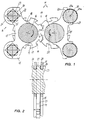
- the drawing shows a cutter 11 with two intermeshing, counter-rotating cutter shafts or cutting rollers 12, whose through-shaft cross-section at intervals (spacing t) of each other cutting discs 13 collect, so that thereby forming gaps a.
- tear-off grooves 14 are formed, which have the shape of oblique recesses with a cutting tooth running in the direction of rotation.
- the cutting disks engage with each other, so they overlap each other.
- broachers 15 run, which, on the side of the cutting shafts distant from the cutting gap 19, engage around these by approximately 180 °. They have streaked edges or clearing edges 17 at their two ends, which strip off particles adhering to the shaft base or at all within the space between the cutting disks a and introduce them into the flow of cutting particles.
- the lower clearing edge 17 is effective, while in the case of a return, which is usually provided to remove blockages, the upper clearing edge becomes effective.
- the reamer consisting of a flat sheet metal stamped part 15 at its upper and lower, away from the cutting gap End holding sections 21 which are provided with openings 22 are.
- the openings 22 in the two holding sections are square in the embodiment.
- openings 22 protrude beams 23 which have the shape of square bars with edged edges.
- circumferential recesses 24 are provided, which are provided in the square rod in such a way that the recess base 25 practically corresponds to the circle inscribed in the square.
- locking projections 27 are formed on all four longitudinal edges 26, the side surfaces of which are axial positioning surfaces 28.
- the arrangement of two beams means that the clearing replacement is in each Directed safely and can both with an adjustable Distance as well as in contact with the shaft bottom 18 of the Cutting shaft 12 run. Because of the exact shape of the reamer, which contribute to a large lead distance between the two beams good stability and low material expenditure guaranteed, reference is expressly made to the drawing.
- the clearers are positioned in a division ratio corresponding to the division t . Theoretically, this could be done by an assembly device, but can be done even more easily by the cutting shaft itself.
- the clearers are accordingly threaded into the spaces a .
- the supports 23 can be pushed in, now in the same profile orientation, ie also with a horizontal and vertical diagonal. Then the straps are turned by 45 ° and fixed in this position.
- the locking projections 27 engage between the reamer and the axial positioning surfaces 28 ensure that the reamer is positioned with a slight play in the middle in the space a between the cutting disks 13.
- the scraper can now fulfill its task, namely to run with its scraper edge 17 on the roller base 18 in operation and to remove from the interstices a objects cut by the cutting disc edges and torn into particles by the tear-off grooves if they adhere there.
- these shredding devices are mainly used as document shredders, but can also be used for shredding other objects, such as packaging, foils or the like.
- the execution in the right half of FIG. 1 differs with otherwise the same training thereby from the previous described reamer design that the reamer 15 in their Holding sections 21 no recess closed on all sides, like on the right side, but a semicircular recess 22a, for engaging in circumferential grooves or recesses 24a are provided in the surface of supports 23a in the form of round rods are provided.
- This will the reamer 15 is also positioned axially. Because the recesses in angularly offset sections the holding portions 21 are provided, finds a certain Locking instead, which the clearing also towards the cutting shaft too fixed. It can be seen that sections 29 of the holding sections over the connecting line reach around between the two central axes 30 of the carriers.
Landscapes
- Engineering & Computer Science (AREA)
- Food Science & Technology (AREA)
- Crushing And Pulverization Processes (AREA)
Claims (12)
- Mécanisme de coupe pour un dispositif de fragmentation, notamment un destructeur de documents (11), avec au moins un arbre de coupe (12), qui présente des disques de coupe (13) écartés axialement l'un de l'autre de a, et avec des dispositifs d'évacuation ou racleurs (15), qui s'engagent respectivement entre deux disques de coupe (13) limitrophes, lesquels racleurs sont asseblés par au moins un support (23, 23a) en un ensemble de racleurs (16), caractérisé en ce que pour le moins le seul support (23, 23a) présente à l'intérieur de l'ensemble de racleurs (16) des surfaces de positionnement axial (28) agissant ensemble avec les racleurs (15), pour le positionnement intermédiaire des racleurs (15).
- Mécanisme de coupe selon la revendication 1, caractérisé en ce que pour chaque racleur (15) sont prévus au moins une surface de positionnement axial (28), de préférence deux surfaces de positionnement axial (28) efficaces dans les deux directions axiales.
- Mécanisme de coupe selon la revendication 1 ou 2, caractérisé en ce que l'écart entre les surfaces de positionnement axial (28) orientées dans la même direction correspond à l'écart (partition t) entre les disques de coupe (13).
- Mécanisme de coupe selon une des revendications précédentes, caractérisé en ce que les surfaces de positionnement axial (28) sont prévues auprès d'éléments de verrouillage (27), qui sont à mettre dans leur situation, laquelle positionne les racleurs (15) de manière axiale, après l'achèvement de l'ensemble de racleurs (16).
- Mécanisme de coupe selon une des revendications précédentes, caractérisé en ce que les surfaces de positionnement axial (28) sont formés par les surfaces latérales d'entailles (24) dans au moins une tige formant le support (23, 23a).
- Mécanisme de coupe selon une des revendications précédentes, caractérisé en ce que chaque ensemble de racleurs (16) présente deux supports (23, 23a).
- Mécanisme de coupe selon une des revendications précédentes, caractérisé en ce que le support (23) présente un profil de support asymétrique de rotation, de préférence un profil polygonal, qui est à la mesure d'un profil de percement d'un percement (22) dans le racleur (15), en ce que des entailles (24) sont prévues dans le domaine des arêtes saillantes (26) du profil de support et en ce que le profil de support et le profil de percement sont immobilisés l'un par rapport à l'autre de manière décalée en direction périphérique pour un engagement à verrouillage.
- Mécanisme de coupe selon une des revendications précédentes, caractérisé en ce que le support (23) est une tige carrée, qui s'engage dans des percements carrés (22) des racleurs (15).
- Mécanisme de coupe selon une des revendications précédentes, caractérisé en ce que les racleurs (15) sont des pièces plate de tôle découpée.
- Procédé pour la fabrication d'un ensemble de racleurs, qui s'engagent dans les espaces intermédiaires de disques de coupe (13) d'un arbre de coupe (12) d'un dispositif de fragmentation, notamment d'un déchiqueteur de documents (11), caracterisé en ce que les racleurs (15) fabriqués en tant que pièces individuelles estampées de tôle, sont rangés, éventuellement utilisant l'arbre de coupe (12) en tant que pièce d'écartement, un support (23) est inséré dans des ouvertures (22) correspondant avec celui-ci à la manière d'un verrou, dans le racleur (15) et ensuite les racleurs sont positionnés sur le support, avec des écarts axiaux prédéterminés par des saillies de verrouillage (27) sur le support (23), par un mouvement angulaire relatif entre le support (23) et les racleurs (15).
- Procédé selon le préambule de la revendication 10, caractérisé en ce que les racleurs, fabriqués en tant que pièces individuelles de tôle découpée, sont rangés éventuellement par usage de l'arbre de coupe (12) en tant que pièce d'écartement, un support (23a) est approché latéralement de l'ensemble de racleurs (16) rangé, par engagement de saillies de verrouillage, prévues sur le support (23a), dans des espaces intermédiaires entre les racleurs (15), et ensuite le support (23a) est immobilisé dans sa position.
- Procédé selon la revendication 11, caractérisé en ce que les supports s'engagent dans des creux (22a) ouverts d'un côté, qui sont décalés l'un par rapport à l'autre en ce qui concerne leurs ouvertures, que l'ensemble de racleurs est fixé entre deux supports.
Applications Claiming Priority (2)
| Application Number | Priority Date | Filing Date | Title |
|---|---|---|---|
| DE4436751 | 1994-10-14 | ||
| DE4436751A DE4436751A1 (de) | 1994-10-14 | 1994-10-14 | Schneidwerkzeug für eine Zerkleinerungsvorrichtung, insbesondere einen Dokumentenvernichter, und Verfahren zur Herstellung eines Räumersatzes dafür |
Publications (2)
| Publication Number | Publication Date |
|---|---|
| EP0706828A1 EP0706828A1 (fr) | 1996-04-17 |
| EP0706828B1 true EP0706828B1 (fr) | 1999-05-26 |
Family
ID=6530776
Family Applications (1)
| Application Number | Title | Priority Date | Filing Date |
|---|---|---|---|
| EP95111796A Expired - Lifetime EP0706828B1 (fr) | 1994-10-14 | 1995-07-27 | Dispositif de coupe, pour déchiqueteur en particulier pour déchiqueteur de documents et procédé de réalisation d'un ensemble racleur pour celui-ci |
Country Status (2)
| Country | Link |
|---|---|
| EP (1) | EP0706828B1 (fr) |
| DE (2) | DE4436751A1 (fr) |
Families Citing this family (2)
| Publication number | Priority date | Publication date | Assignee | Title |
|---|---|---|---|---|
| DE19610048A1 (de) * | 1996-03-14 | 1997-09-18 | Schleicher & Co Int | Schriftgutvernichter |
| CN109248758B (zh) * | 2017-07-14 | 2020-05-08 | 江苏豌豆垃圾处理器制造有限公司 | 一种家用垃圾处理器的多铰刀刀盘机构 |
Family Cites Families (7)
| Publication number | Priority date | Publication date | Assignee | Title |
|---|---|---|---|---|
| GB650200A (en) * | 1948-09-29 | 1951-02-14 | Oscar Legg | Improvements in and relating to paper shredding machines |
| DE2335360A1 (de) * | 1973-07-11 | 1975-02-06 | Schleicher Co Feinwerktech | Vorrichtung zum zerkleinern von abfaellen |
| DE2338654C2 (de) * | 1973-07-31 | 1986-04-10 | Adolf 7460 Balingen Ehinger jun. | Zerkleinerungsvorrichtung, insbesondere Aktenvernichter |
| DE3112666A1 (de) | 1981-03-31 | 1982-10-14 | Feinwerktechnik Schleicher & Co, 7778 Markdorf | Abstreiffinger im reisswerk einer zerreissmaschine fuer text- und datentraeger |
| DE4123293A1 (de) * | 1991-07-13 | 1993-01-21 | Schwelling Hermann | Abstreiferkamm, insbesondere fuer klein-aktenvernichter |
| US5178336A (en) * | 1991-10-11 | 1993-01-12 | John W. Wagner | Machine for cutting disposable containers |
| EP0616850B1 (fr) * | 1993-03-22 | 1997-07-23 | Hermann Schwelling | Destructeur de documents |
-
1994
- 1994-10-14 DE DE4436751A patent/DE4436751A1/de not_active Withdrawn
-
1995
- 1995-07-27 DE DE59506015T patent/DE59506015D1/de not_active Expired - Lifetime
- 1995-07-27 EP EP95111796A patent/EP0706828B1/fr not_active Expired - Lifetime
Also Published As
| Publication number | Publication date |
|---|---|
| EP0706828A1 (fr) | 1996-04-17 |
| DE4436751A1 (de) | 1996-04-18 |
| DE59506015D1 (de) | 1999-07-01 |
Similar Documents
| Publication | Publication Date | Title |
|---|---|---|
| EP2629917B1 (fr) | Fraise pour dent et procédé de fraisage des dents d'éléments d'engrenage à dents | |
| EP0875356A2 (fr) | Extrudeuse multi-vis, notamment extrudeuse à deux vis | |
| DE1552633A1 (de) | Vorrichtung zum Beschneiden mindestens einer Kante eines Blechbandes | |
| DE3390257C2 (fr) | ||
| DE102009035232B4 (de) | Schneidsatz für Haarschneidemaschinen | |
| DE2659231A1 (de) | Aktenvernichter | |
| DE19712661A1 (de) | Schneidwerk eines Dokumentenvernichters | |
| DE2848554A1 (de) | Stanzmesser | |
| EP0422272B1 (fr) | Dispositif de malaxage et pétrissage | |
| EP0795353A1 (fr) | Déchiqueteur de documents | |
| DE3712953A1 (de) | Schneidwerkzeug | |
| DE3505075C2 (fr) | ||
| WO2003013802A2 (fr) | Feuille de coupe pour le systeme de coupe d'un rasoir | |
| WO2011057726A2 (fr) | Lame de coupe d'un dispositif de coupe de tabac | |
| EP0706828B1 (fr) | Dispositif de coupe, pour déchiqueteur en particulier pour déchiqueteur de documents et procédé de réalisation d'un ensemble racleur pour celui-ci | |
| EP0300279B1 (fr) | Méthode pour conditionner un tapis de fourage coupé et rouleaux conditionneurs pour la mise en oeuvre de ce procédé | |
| EP0590408A1 (fr) | Outil pour le fraisage de mortaises et de rainures | |
| DE2848046C2 (fr) | ||
| EP1329151A1 (fr) | Taille-haie | |
| DE3209246C2 (de) | Messerträger eines Hobelmessers | |
| AT392317B (de) | Flachschluessel sowie schloss | |
| DE102008049317B4 (de) | Schneidmesser für einen Kreiselmäher, Kreiselmäher mit einem derartigen Schneidmesser sowie Verfahren zum Herstellen eines derartigen Schneidmessers | |
| DE2811376C3 (de) | Rotor für Prallmühlen, insbesondere für Sandprallmühlen | |
| DE602004002747T2 (de) | Runde wellenförmige Klinge und Klingenmodul für Schredder | |
| WO2007121836A9 (fr) | rouleau À lames de granulation de joncs en matière plastique |
Legal Events
| Date | Code | Title | Description |
|---|---|---|---|
| PUAI | Public reference made under article 153(3) epc to a published international application that has entered the european phase |
Free format text: ORIGINAL CODE: 0009012 |
|
| AK | Designated contracting states |
Kind code of ref document: A1 Designated state(s): DE FR GB IT |
|
| 17P | Request for examination filed |
Effective date: 19960507 |
|
| GRAG | Despatch of communication of intention to grant |
Free format text: ORIGINAL CODE: EPIDOS AGRA |
|
| GRAG | Despatch of communication of intention to grant |
Free format text: ORIGINAL CODE: EPIDOS AGRA |
|
| GRAG | Despatch of communication of intention to grant |
Free format text: ORIGINAL CODE: EPIDOS AGRA |
|
| GRAH | Despatch of communication of intention to grant a patent |
Free format text: ORIGINAL CODE: EPIDOS IGRA |
|
| 17Q | First examination report despatched |
Effective date: 19981012 |
|
| GRAH | Despatch of communication of intention to grant a patent |
Free format text: ORIGINAL CODE: EPIDOS IGRA |
|
| GRAA | (expected) grant |
Free format text: ORIGINAL CODE: 0009210 |
|
| AK | Designated contracting states |
Kind code of ref document: B1 Designated state(s): DE FR GB IT |
|
| PG25 | Lapsed in a contracting state [announced via postgrant information from national office to epo] |
Ref country code: IT Free format text: LAPSE BECAUSE OF FAILURE TO SUBMIT A TRANSLATION OF THE DESCRIPTION OR TO PAY THE FEE WITHIN THE PRESCRIBED TIME-LIMIT;WARNING: LAPSES OF ITALIAN PATENTS WITH EFFECTIVE DATE BEFORE 2007 MAY HAVE OCCURRED AT ANY TIME BEFORE 2007. THE CORRECT EFFECTIVE DATE MAY BE DIFFERENT FROM THE ONE RECORDED. Effective date: 19990526 |
|
| REF | Corresponds to: |
Ref document number: 59506015 Country of ref document: DE Date of ref document: 19990701 |
|
| ET | Fr: translation filed | ||
| GBT | Gb: translation of ep patent filed (gb section 77(6)(a)/1977) |
Effective date: 19990624 |
|
| PLBE | No opposition filed within time limit |
Free format text: ORIGINAL CODE: 0009261 |
|
| STAA | Information on the status of an ep patent application or granted ep patent |
Free format text: STATUS: NO OPPOSITION FILED WITHIN TIME LIMIT |
|
| 26N | No opposition filed | ||
| REG | Reference to a national code |
Ref country code: GB Ref legal event code: IF02 |
|
| PGFP | Annual fee paid to national office [announced via postgrant information from national office to epo] |
Ref country code: FR Payment date: 20110729 Year of fee payment: 17 |
|
| PGFP | Annual fee paid to national office [announced via postgrant information from national office to epo] |
Ref country code: GB Payment date: 20110721 Year of fee payment: 17 |
|
| GBPC | Gb: european patent ceased through non-payment of renewal fee |
Effective date: 20120727 |
|
| REG | Reference to a national code |
Ref country code: FR Ref legal event code: ST Effective date: 20130329 |
|
| PG25 | Lapsed in a contracting state [announced via postgrant information from national office to epo] |
Ref country code: FR Free format text: LAPSE BECAUSE OF NON-PAYMENT OF DUE FEES Effective date: 20120731 Ref country code: GB Free format text: LAPSE BECAUSE OF NON-PAYMENT OF DUE FEES Effective date: 20120727 |
|
| PGFP | Annual fee paid to national office [announced via postgrant information from national office to epo] |
Ref country code: DE Payment date: 20140723 Year of fee payment: 20 |
|
| REG | Reference to a national code |
Ref country code: DE Ref legal event code: R071 Ref document number: 59506015 Country of ref document: DE |