EP0706902A1 - Verfahren und Vorrichtung zum Schutz von Fahrzeugradteilen - Google Patents
Verfahren und Vorrichtung zum Schutz von Fahrzeugradteilen Download PDFInfo
- Publication number
- EP0706902A1 EP0706902A1 EP95115607A EP95115607A EP0706902A1 EP 0706902 A1 EP0706902 A1 EP 0706902A1 EP 95115607 A EP95115607 A EP 95115607A EP 95115607 A EP95115607 A EP 95115607A EP 0706902 A1 EP0706902 A1 EP 0706902A1
- Authority
- EP
- European Patent Office
- Prior art keywords
- wheel
- rim
- valve
- disc
- towards
- Prior art date
- Legal status (The legal status is an assumption and is not a legal conclusion. Google has not performed a legal analysis and makes no representation as to the accuracy of the status listed.)
- Granted
Links
Images


Classifications
-
- B—PERFORMING OPERATIONS; TRANSPORTING
- B60—VEHICLES IN GENERAL
- B60B—VEHICLE WHEELS; CASTORS; AXLES FOR WHEELS OR CASTORS; INCREASING WHEEL ADHESION
- B60B3/00—Disc wheels, i.e. wheels with load-supporting disc body
- B60B3/002—Disc wheels, i.e. wheels with load-supporting disc body characterised by the shape of the disc
- B60B3/005—Disc wheels, i.e. wheels with load-supporting disc body characterised by the shape of the disc in the section adjacent to rim
-
- B—PERFORMING OPERATIONS; TRANSPORTING
- B60—VEHICLES IN GENERAL
- B60B—VEHICLE WHEELS; CASTORS; AXLES FOR WHEELS OR CASTORS; INCREASING WHEEL ADHESION
- B60B21/00—Rims
- B60B21/02—Rims characterised by transverse section
-
- B—PERFORMING OPERATIONS; TRANSPORTING
- B60—VEHICLES IN GENERAL
- B60B—VEHICLE WHEELS; CASTORS; AXLES FOR WHEELS OR CASTORS; INCREASING WHEEL ADHESION
- B60B21/00—Rims
- B60B21/02—Rims characterised by transverse section
- B60B21/023—Rims characterised by transverse section the transverse section being non-symmetrical
-
- B—PERFORMING OPERATIONS; TRANSPORTING
- B60—VEHICLES IN GENERAL
- B60B—VEHICLE WHEELS; CASTORS; AXLES FOR WHEELS OR CASTORS; INCREASING WHEEL ADHESION
- B60B21/00—Rims
- B60B21/08—Rims characterised by having braking surfaces
-
- B—PERFORMING OPERATIONS; TRANSPORTING
- B60—VEHICLES IN GENERAL
- B60B—VEHICLE WHEELS; CASTORS; AXLES FOR WHEELS OR CASTORS; INCREASING WHEEL ADHESION
- B60B21/00—Rims
- B60B21/12—Appurtenances, e.g. lining bands
-
- B—PERFORMING OPERATIONS; TRANSPORTING
- B60—VEHICLES IN GENERAL
- B60B—VEHICLE WHEELS; CASTORS; AXLES FOR WHEELS OR CASTORS; INCREASING WHEEL ADHESION
- B60B3/00—Disc wheels, i.e. wheels with load-supporting disc body
- B60B3/04—Disc wheels, i.e. wheels with load-supporting disc body with a single disc body not integral with rim, i.e. disc body and rim being manufactured independently and then permanently attached to each other in a second step, e.g. by welding
- B60B3/041—Disc wheels, i.e. wheels with load-supporting disc body with a single disc body not integral with rim, i.e. disc body and rim being manufactured independently and then permanently attached to each other in a second step, e.g. by welding characterised by the attachment of rim to wheel disc
- B60B3/044—Disc wheels, i.e. wheels with load-supporting disc body with a single disc body not integral with rim, i.e. disc body and rim being manufactured independently and then permanently attached to each other in a second step, e.g. by welding characterised by the attachment of rim to wheel disc characterised by cross-sectional details of the attachment, e.g. the profile
-
- B—PERFORMING OPERATIONS; TRANSPORTING
- B60—VEHICLES IN GENERAL
- B60C—VEHICLE TYRES; TYRE INFLATION; TYRE CHANGING; CONNECTING VALVES TO INFLATABLE ELASTIC BODIES IN GENERAL; DEVICES OR ARRANGEMENTS RELATED TO TYRES
- B60C29/00—Arrangements of tyre-inflating valves to tyres or rims; Accessories for tyre-inflating valves, not otherwise provided for
- B60C29/02—Connection to rims
Definitions
- the invention relates to vehicle wheels fitted with valves for inflating tires, in particular those fitted with rims with a hollow base, the valve hole of which is located in the bottom of the groove or in the side of the groove.
- Wheels of this type frequently used for commercial vehicles, are generally fitted with a valve, the stem of which substantially extends along the outer wall of the rim (opposite the pneumatic cavity), to reach the exterior of the vehicle by crossing the disc. wheel by an opening, so as to make accessible the threaded end piece and its cap.
- the valve stem represents a protuberance in the volume located between rim and axle, volume in which the hub and the braking device are housed.
- the invention has the effects and advantages, on the one hand, of reducing the possibilities of penetration of foreign bodies into the cavities between rim and hub, or at least of reducing the size of those which could still penetrate, of facilitating evacuation of those who are about to enter, or have entered these volumes, and on the other hand, to eliminate the risks of hooking and attacking the valve stem or other mechanical parts in the event of penetration of a foreign body, which improves safety, the lifespan of rolling stock, and reduces maintenance costs.
- the invention relates to a method of protecting the wheels and their components (valves, rims, braking system) exposed to shocks due to foreign objects entering the volume between the rim, the wheel disc, the hub and its attachments.
- the invention includes devices placed in this volume and whose main roles are to strongly limit the penetration of foreign bodies into said volume, and to protect the valve elements from the shocks of these foreign bodies.
- the invention also includes the wheels equipped with these devices, and their production methods.
- the invention relates to a method of protecting a wheel, characterized in that at least partially occupied by a solid material, the volume of revolution V1 delimited by a part of the surfaces of the rim and possibly of that of the disc. wheel directed towards the axle, the occupied volume enveloping or encompassing in a solid of revolution the elements of the valve located outside the tire cavity and inside the wheel.
- the volume V1 can be defined by the rotation around the axis of the wheel, of a surface included in the plane including this axis of rotation and the valve, and delimited on the one hand by the rim and the wheel disc or the rim fastening elements, on the other hand by the circular projection on this plane of the valve elements.
- Solid material means any material chosen from the fields of metals, or plastics, rubbers, resins or composites, provided that it retains good dimensional stability and good mechanical properties by resisting temperatures in contact with the rim reached during continuous operation while driving, and temperature spikes due to braking.
- the protection process is characterized in that the filling material is molded directly between the surfaces of the rim and of the wheel disc and of the mold jigs, the parts of the valve being able to be in place.
- the protection method is characterized in that the solid protection material envelops the valve elements radially towards the inside of the wheel to form a solid of revolution whose external surface directed towards the axle is substantially continuous.
- the protection method is characterized in that a removable profile of filling material is inserted into the volume between the surfaces under the rim towards the inside of the wheel disc.
- the invention relates to a device allowing the implementation of the method, characterized in that it comprises a solid filling in the mounting position in the wheel, at least the volume of revolution V1 defined above, this filling material being able to be fixed or removable, solid or hollow, optionally comprising porosities, where appropriate open, and enveloping radially towards the inside of the wheel, at least partially the surface of revolution generated by the rotation of the valve, and its surface directed towards the hub being as close as possible to a surface of revolution and substantially without roughness, and the zone surrounding the valve substantially regular.
- the wheel protection device comprising a rim equipped with a valve forming a protrusion radially towards the inside of the wheel is characterized in that it comprises a solid of revolution, which in the position of mounting in the wheel, is adjacent to the rim, and envelops at least partially radially the surface of revolution generated by the rotation of the valve around the axis of the wheel.
- the device is characterized in that it is, in the mounting position in the wheel, between the rim and at least one side of the wheel disc.
- the device according to the invention is characterized in that it comprises a filling material molded into the volume between a part of the rim, a part of the wheel disc when it is present, and the surface of revolution generated by the rotation valve.
- the device according to the invention can also be produced with one (or more) substantially circular profile (s) of forged, rolled, drawn, rolled, molded or extruded material, which is introduced into the volume V1 or around the volume V1.
- the device according to the invention is characterized in that it is formed of at least one profile of solid material which is elastically deformable in a non-permanent manner, and which can be introduced into the volume generated by the rotation of the valve, and adjacent to the rim.
- the device is characterized in that it has a shoulder oriented radially towards the inside of the wheel, axially towards the brake disc to minimize the passage surface for foreign bodies between the rim and the brake disc, while leaving free the space allocated for the passage of the brake caliper.
- the filling of the protected volume may be only very partial, for example in the case where the protective material plays the role of an envelope for this volume.
- the device is characterized in that it forms a casing enveloping radially towards the inside of the wheel, at least partially the surface of revolution generated by the rotation of the valve.
- the upper limit of the value of the wrapped volume may be greater than the volume V1 insofar as at least part of the thickness of the profit passes over the valve, and / or comprises the shoulder defined above.
- the profiles that can be used for the protection devices can be formed from one or more parts housed in the volume V1 or surrounding it.
- An advantage in one elastically deformable piece to pass under the rim hollow is an advantageous embodiment.
- the material filling or enveloping the volume of revolution is advantageously provided with a recess allowing the housing of the valve stem and the valve base in the vicinity of the rim, so as to avoid excess thickness.
- An advantageous type of embodiment consists in the choice of an elastic material in the form of a transversely split ring which can be deformed in a non-permanent manner, for example by passing one of the ends under the other with reduction in the diameter of l ring just enough to be able to pass it under the hollow rim to introduce it into the space of the wheel containing the valve stem, and letting it resume its original shape in volume V1 or around it.
- An embodiment comprising only one transverse slot is particularly advantageous for a simple and practical production and assembly.
- the two ends of the slot in the state free of any stress are separated by an interval, which is reduced by elastic deformation of the device for its presentation for mounting, and its maintenance in wheel.
- Another advantageous embodiment consists in the choice of an elastic material in the form of a split or continuous ring which can be deformed non-permanently by torsion to obtain a non-planar left shape allowing it to pass under the hollow rim and let the ring regain its shape by positioning it in volume V1 or around it.
- an elastic material in the form of a split or continuous ring which can be deformed non-permanently by torsion to obtain a non-planar left shape allowing it to pass under the hollow rim and let the ring regain its shape by positioning it in volume V1 or around it.
- the device according to the advantageous embodiments is characterized in that it is shaped so that, in the position of use in the wheel, its retention in place is ensured by its adhesion and the friction forces in the case of its molding in place, or by the elastic forces and the friction forces exerted on the (or the) profile (s) introduced (s) into the wheel after its (their) elastic deformation.
- the device does not require any additional means of attachment to the wheel, which facilitates obtaining surfaces of revolution devoid of protuberance or hollows, which avoids points of hooking up with foreign bodies which could still have entered the wheel. Additional advantages of such a device are also found in the ease and speed of its assembly or disassembly operations and maintenance interventions.
- the device according to the invention is characterized in that the solid protective material envelops the valve elements radially towards the inside of the wheel to form a solid of revolution, the external surface of which faces the axle. is substantially continuous and without roughness.
- the vehicle wheel comprising a rim equipped with a valve forming a protrusion radially towards the inside of the wheel, is characterized in that it is provided with one of the aforementioned devices.
- a method of manufacturing a wheel for a vehicle comprising a rim fitted with a valve forming a protrusion radially towards the inside of the wheel, is characterized in that it includes the use of the aforementioned means.
- the current name of the wheel concerned according to the ETRTO (European Tire Rim Technical Organization) classifications or ISO standards is: "22.5 x 8.25 - 10-158" corresponding to a rim diameter at the seat of 22.5 inches or 571.5 mm with a wheel disc with an offset of 158 mm.
- the profile can be produced from a strip of ordinary steel sheet or spring steel, the dimensions of which are close to the following: Thickness: 1.5 mm, Length: 1643 mm, Width: 81.4 mm shaped into a ring by welding it end to end.
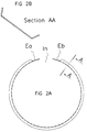
- the ring is then rolled to give it a flattened U-shaped profile defined in Figure 2.b with a manufacturing diameter under the hollow of 523 mm.
- each end Ea, Eb can be pierced with a hole allowing the passage of a temporary blocking piece which facilitates the handling of the closed ring.
- the latter can then enter the wheel by an axial displacement in the volume V1, taking care to arrange the recess Ea under the valve.
- the elasticity of the ring causing the separation of its ends, it reaches its mounting position ( Figure 3.c) for which the ends Ea, Eb are substantially in contact face to face.
- the ring then still has an elastic deformation which constrains it to an internal mounting diameter (Dmi) of approximately 498 mm.
- the corresponding elastic forces place the ring on the internal surface of the volume V1 of the wheel and keep it in the position of protection of the internal volume V1 and of the valve.
- an additional blocking of the rotation of the ring can be added by providing a wing of the profile with at least one lug extending it in one of the openings of the wheel disc.
- a wing of the profile with at least one lug extending it in one of the openings of the wheel disc.
Landscapes
- Engineering & Computer Science (AREA)
- Mechanical Engineering (AREA)
- Braking Arrangements (AREA)
- Automobile Manufacture Line, Endless Track Vehicle, Trailer (AREA)
Applications Claiming Priority (2)
| Application Number | Priority Date | Filing Date | Title |
|---|---|---|---|
| FR9412263A FR2725665A1 (fr) | 1994-10-12 | 1994-10-12 | Procede et dispositif de protection des elements des roues de vehicules |
| FR9412263 | 1994-10-12 |
Publications (2)
| Publication Number | Publication Date |
|---|---|
| EP0706902A1 true EP0706902A1 (de) | 1996-04-17 |
| EP0706902B1 EP0706902B1 (de) | 1999-01-13 |
Family
ID=9467848
Family Applications (1)
| Application Number | Title | Priority Date | Filing Date |
|---|---|---|---|
| EP95115607A Expired - Lifetime EP0706902B1 (de) | 1994-10-12 | 1995-10-04 | Verfahren und Vorrichtung zum Schutz von Fahrzeugradteilen |
Country Status (5)
| Country | Link |
|---|---|
| EP (1) | EP0706902B1 (de) |
| AT (1) | ATE175631T1 (de) |
| DE (1) | DE69507241T2 (de) |
| ES (1) | ES2128626T3 (de) |
| FR (1) | FR2725665A1 (de) |
Cited By (2)
| Publication number | Priority date | Publication date | Assignee | Title |
|---|---|---|---|---|
| WO2006019749A1 (en) * | 2004-07-14 | 2006-02-23 | Bendix Spicer Foundation Brake Llc | Wheel valve stem shield for air disc brake applications |
| EP1982852A1 (de) * | 2007-04-17 | 2008-10-22 | Bendix Spicer Foundation Brake LLC | Warnsensor für falsches Rad |
Citations (3)
| Publication number | Priority date | Publication date | Assignee | Title |
|---|---|---|---|---|
| EP0032747A1 (de) * | 1980-01-22 | 1981-07-29 | Georg Fischer Aktiengesellschaft | Einteilige, gegossene Tiefbettfelge für ein Kraftfahrzeugrad |
| US4407348A (en) * | 1981-01-23 | 1983-10-04 | Caterpillar Tractor Co. | Multi-piece wheel structure |
| DE4332894A1 (de) * | 1993-09-22 | 1995-03-30 | Mannesmann Ag | Ventilschutz für luftbereifte Scheibenräder |
-
1994
- 1994-10-12 FR FR9412263A patent/FR2725665A1/fr active Pending
-
1995
- 1995-10-04 AT AT95115607T patent/ATE175631T1/de not_active IP Right Cessation
- 1995-10-04 DE DE69507241T patent/DE69507241T2/de not_active Expired - Fee Related
- 1995-10-04 EP EP95115607A patent/EP0706902B1/de not_active Expired - Lifetime
- 1995-10-04 ES ES95115607T patent/ES2128626T3/es not_active Expired - Lifetime
Patent Citations (3)
| Publication number | Priority date | Publication date | Assignee | Title |
|---|---|---|---|---|
| EP0032747A1 (de) * | 1980-01-22 | 1981-07-29 | Georg Fischer Aktiengesellschaft | Einteilige, gegossene Tiefbettfelge für ein Kraftfahrzeugrad |
| US4407348A (en) * | 1981-01-23 | 1983-10-04 | Caterpillar Tractor Co. | Multi-piece wheel structure |
| DE4332894A1 (de) * | 1993-09-22 | 1995-03-30 | Mannesmann Ag | Ventilschutz für luftbereifte Scheibenräder |
Cited By (2)
| Publication number | Priority date | Publication date | Assignee | Title |
|---|---|---|---|---|
| WO2006019749A1 (en) * | 2004-07-14 | 2006-02-23 | Bendix Spicer Foundation Brake Llc | Wheel valve stem shield for air disc brake applications |
| EP1982852A1 (de) * | 2007-04-17 | 2008-10-22 | Bendix Spicer Foundation Brake LLC | Warnsensor für falsches Rad |
Also Published As
| Publication number | Publication date |
|---|---|
| ES2128626T3 (es) | 1999-05-16 |
| ATE175631T1 (de) | 1999-01-15 |
| DE69507241D1 (de) | 1999-02-25 |
| EP0706902B1 (de) | 1999-01-13 |
| DE69507241T2 (de) | 1999-06-10 |
| FR2725665A1 (fr) | 1996-04-19 |
Similar Documents
| Publication | Publication Date | Title |
|---|---|---|
| FR2993500A1 (fr) | Bande de roulement pour pneu d'essieu moteur de poids lourd et pneu | |
| FR3027256A1 (fr) | Dispositif de protection dun flanc de pneu | |
| FR2925373A1 (fr) | Procede de fabrication d'une piece structurelle hybride, et piece ainsi obtenue | |
| EP2849956B1 (de) | Verbesserte geräuschreduzierende vorrichtung für einen reifen | |
| CH624890A5 (de) | ||
| EP0755807A2 (de) | Rad eines Nutzfahrzeuges mit einem aussen an der Radscheibe mündenden Ventil | |
| FR2492492A1 (fr) | Procede et dispositif d'insonorisation d'une roue metallique | |
| CA1253535A (fr) | Jante en une seule piece conformee de maniere a retenir le bourrelet sur son siege et procede de montage de l'enveloppe sur sa jante | |
| FR2698823A1 (fr) | Dispositif d'anneau perfectionné pour roulage à plat. | |
| CA2300506A1 (fr) | Sculpture de bande de roulement et moule | |
| EP4185528A1 (de) | Hitzeschildanordnung | |
| EP2900487B1 (de) | Verbesserte resonanzgeräusch vermindernde vorrichtung für einen reifen | |
| EP0706902B1 (de) | Verfahren und Vorrichtung zum Schutz von Fahrzeugradteilen | |
| FR2744953A1 (fr) | Jante de roue a rayons destinee a etre equipee d'un pneumatique sans chambre, et roue a rayons ainsi equipee | |
| FR2827548A1 (fr) | Ensemble monte tubeless pour cycle, jante et pneumatique tubeless | |
| CA2603272C (fr) | Anneau de verrouillage dans un ensemble de montage d'un pneumatique sur un moyeu de vehicule | |
| EP0155210B1 (de) | Geteilter Luftschlauch | |
| EP0557164A1 (de) | Vorrichtung zum Festspannen eines Luftreifens auf einer Felge | |
| EP3727883A1 (de) | Anordnung für einen reifen | |
| CA2124412C (fr) | Valve de gonflage et procede utilisant ladite valve pour gonflage d'un pneumatique avec anneau d'etancheite | |
| FR2969237A1 (fr) | Dispositif de suspension de roue pour vehicule automobile comportant une bague de protection du roulement de roue | |
| FR2653384A1 (fr) | Dispositif de roue, rouleau, galet ou analogue. | |
| WO2001070542A1 (fr) | Accessoire pour flap | |
| EP3695990B1 (de) | Endhülse einer aufpumpvorrichtung für selbstreparierende reifen | |
| CA2217467A1 (fr) | Dispositif de roulage a plat pour vehicule automobile, en particulier pour vehicule de tourisme |
Legal Events
| Date | Code | Title | Description |
|---|---|---|---|
| PUAI | Public reference made under article 153(3) epc to a published international application that has entered the european phase |
Free format text: ORIGINAL CODE: 0009012 |
|
| AK | Designated contracting states |
Kind code of ref document: A1 Designated state(s): AT DE ES FR GB IT SE |
|
| 17P | Request for examination filed |
Effective date: 19961017 |
|
| GRAG | Despatch of communication of intention to grant |
Free format text: ORIGINAL CODE: EPIDOS AGRA |
|
| 17Q | First examination report despatched |
Effective date: 19980108 |
|
| GRAG | Despatch of communication of intention to grant |
Free format text: ORIGINAL CODE: EPIDOS AGRA |
|
| GRAH | Despatch of communication of intention to grant a patent |
Free format text: ORIGINAL CODE: EPIDOS IGRA |
|
| GRAH | Despatch of communication of intention to grant a patent |
Free format text: ORIGINAL CODE: EPIDOS IGRA |
|
| GRAA | (expected) grant |
Free format text: ORIGINAL CODE: 0009210 |
|
| AK | Designated contracting states |
Kind code of ref document: B1 Designated state(s): AT DE ES FR GB IT SE |
|
| PG25 | Lapsed in a contracting state [announced via postgrant information from national office to epo] |
Ref country code: SE Free format text: THE PATENT HAS BEEN ANNULLED BY A DECISION OF A NATIONAL AUTHORITY Effective date: 19990113 Ref country code: AT Free format text: LAPSE BECAUSE OF FAILURE TO SUBMIT A TRANSLATION OF THE DESCRIPTION OR TO PAY THE FEE WITHIN THE PRESCRIBED TIME-LIMIT Effective date: 19990113 |
|
| REF | Corresponds to: |
Ref document number: 175631 Country of ref document: AT Date of ref document: 19990115 Kind code of ref document: T |
|
| REF | Corresponds to: |
Ref document number: 69507241 Country of ref document: DE Date of ref document: 19990225 |
|
| GBT | Gb: translation of ep patent filed (gb section 77(6)(a)/1977) |
Effective date: 19990218 |
|
| ITF | It: translation for a ep patent filed | ||
| REG | Reference to a national code |
Ref country code: ES Ref legal event code: FG2A Ref document number: 2128626 Country of ref document: ES Kind code of ref document: T3 |
|
| PLBE | No opposition filed within time limit |
Free format text: ORIGINAL CODE: 0009261 |
|
| STAA | Information on the status of an ep patent application or granted ep patent |
Free format text: STATUS: NO OPPOSITION FILED WITHIN TIME LIMIT |
|
| 26N | No opposition filed | ||
| REG | Reference to a national code |
Ref country code: GB Ref legal event code: IF02 |
|
| PGFP | Annual fee paid to national office [announced via postgrant information from national office to epo] |
Ref country code: GB Payment date: 20030929 Year of fee payment: 9 |
|
| PGFP | Annual fee paid to national office [announced via postgrant information from national office to epo] |
Ref country code: FR Payment date: 20031009 Year of fee payment: 9 |
|
| PGFP | Annual fee paid to national office [announced via postgrant information from national office to epo] |
Ref country code: DE Payment date: 20031010 Year of fee payment: 9 |
|
| PGFP | Annual fee paid to national office [announced via postgrant information from national office to epo] |
Ref country code: ES Payment date: 20031017 Year of fee payment: 9 |
|
| PG25 | Lapsed in a contracting state [announced via postgrant information from national office to epo] |
Ref country code: GB Free format text: LAPSE BECAUSE OF NON-PAYMENT OF DUE FEES Effective date: 20041004 |
|
| PG25 | Lapsed in a contracting state [announced via postgrant information from national office to epo] |
Ref country code: ES Free format text: LAPSE BECAUSE OF NON-PAYMENT OF DUE FEES Effective date: 20041005 |
|
| PG25 | Lapsed in a contracting state [announced via postgrant information from national office to epo] |
Ref country code: DE Free format text: LAPSE BECAUSE OF NON-PAYMENT OF DUE FEES Effective date: 20050503 |
|
| GBPC | Gb: european patent ceased through non-payment of renewal fee |
Effective date: 20041004 |
|
| PG25 | Lapsed in a contracting state [announced via postgrant information from national office to epo] |
Ref country code: FR Free format text: LAPSE BECAUSE OF NON-PAYMENT OF DUE FEES Effective date: 20050630 |
|
| REG | Reference to a national code |
Ref country code: FR Ref legal event code: ST |
|
| PG25 | Lapsed in a contracting state [announced via postgrant information from national office to epo] |
Ref country code: IT Free format text: LAPSE BECAUSE OF NON-PAYMENT OF DUE FEES;WARNING: LAPSES OF ITALIAN PATENTS WITH EFFECTIVE DATE BEFORE 2007 MAY HAVE OCCURRED AT ANY TIME BEFORE 2007. THE CORRECT EFFECTIVE DATE MAY BE DIFFERENT FROM THE ONE RECORDED. Effective date: 20051004 |
|
| REG | Reference to a national code |
Ref country code: ES Ref legal event code: FD2A Effective date: 20041005 |