EP0706902A1 - Process and apparatus for protecting parts of vehicle wheels - Google Patents
Process and apparatus for protecting parts of vehicle wheels Download PDFInfo
- Publication number
- EP0706902A1 EP0706902A1 EP95115607A EP95115607A EP0706902A1 EP 0706902 A1 EP0706902 A1 EP 0706902A1 EP 95115607 A EP95115607 A EP 95115607A EP 95115607 A EP95115607 A EP 95115607A EP 0706902 A1 EP0706902 A1 EP 0706902A1
- Authority
- EP
- European Patent Office
- Prior art keywords
- wheel
- rim
- valve
- disc
- towards
- Prior art date
- Legal status (The legal status is an assumption and is not a legal conclusion. Google has not performed a legal analysis and makes no representation as to the accuracy of the status listed.)
- Granted
Links
Images


Classifications
-
- B—PERFORMING OPERATIONS; TRANSPORTING
- B60—VEHICLES IN GENERAL
- B60B—VEHICLE WHEELS; CASTORS; AXLES FOR WHEELS OR CASTORS; INCREASING WHEEL ADHESION
- B60B3/00—Disc wheels, i.e. wheels with load-supporting disc body
- B60B3/002—Disc wheels, i.e. wheels with load-supporting disc body characterised by the shape of the disc
- B60B3/005—Disc wheels, i.e. wheels with load-supporting disc body characterised by the shape of the disc in the section adjacent to rim
-
- B—PERFORMING OPERATIONS; TRANSPORTING
- B60—VEHICLES IN GENERAL
- B60B—VEHICLE WHEELS; CASTORS; AXLES FOR WHEELS OR CASTORS; INCREASING WHEEL ADHESION
- B60B21/00—Rims
- B60B21/02—Rims characterised by transverse section
-
- B—PERFORMING OPERATIONS; TRANSPORTING
- B60—VEHICLES IN GENERAL
- B60B—VEHICLE WHEELS; CASTORS; AXLES FOR WHEELS OR CASTORS; INCREASING WHEEL ADHESION
- B60B21/00—Rims
- B60B21/02—Rims characterised by transverse section
- B60B21/023—Rims characterised by transverse section the transverse section being non-symmetrical
-
- B—PERFORMING OPERATIONS; TRANSPORTING
- B60—VEHICLES IN GENERAL
- B60B—VEHICLE WHEELS; CASTORS; AXLES FOR WHEELS OR CASTORS; INCREASING WHEEL ADHESION
- B60B21/00—Rims
- B60B21/08—Rims characterised by having braking surfaces
-
- B—PERFORMING OPERATIONS; TRANSPORTING
- B60—VEHICLES IN GENERAL
- B60B—VEHICLE WHEELS; CASTORS; AXLES FOR WHEELS OR CASTORS; INCREASING WHEEL ADHESION
- B60B21/00—Rims
- B60B21/12—Appurtenances, e.g. lining bands
-
- B—PERFORMING OPERATIONS; TRANSPORTING
- B60—VEHICLES IN GENERAL
- B60B—VEHICLE WHEELS; CASTORS; AXLES FOR WHEELS OR CASTORS; INCREASING WHEEL ADHESION
- B60B3/00—Disc wheels, i.e. wheels with load-supporting disc body
- B60B3/04—Disc wheels, i.e. wheels with load-supporting disc body with a single disc body not integral with rim, i.e. disc body and rim being manufactured independently and then permanently attached to each other in a second step, e.g. by welding
- B60B3/041—Disc wheels, i.e. wheels with load-supporting disc body with a single disc body not integral with rim, i.e. disc body and rim being manufactured independently and then permanently attached to each other in a second step, e.g. by welding characterised by the attachment of rim to wheel disc
- B60B3/044—Disc wheels, i.e. wheels with load-supporting disc body with a single disc body not integral with rim, i.e. disc body and rim being manufactured independently and then permanently attached to each other in a second step, e.g. by welding characterised by the attachment of rim to wheel disc characterised by cross-sectional details of the attachment, e.g. the profile
-
- B—PERFORMING OPERATIONS; TRANSPORTING
- B60—VEHICLES IN GENERAL
- B60C—VEHICLE TYRES; TYRE INFLATION; TYRE CHANGING; CONNECTING VALVES TO INFLATABLE ELASTIC BODIES IN GENERAL; DEVICES OR ARRANGEMENTS RELATED TO TYRES
- B60C29/00—Arrangements of tyre-inflating valves to tyres or rims; Accessories for tyre-inflating valves, not otherwise provided for
- B60C29/02—Connection to rims
Definitions
- the invention relates to vehicle wheels fitted with valves for inflating tires, in particular those fitted with rims with a hollow base, the valve hole of which is located in the bottom of the groove or in the side of the groove.
- Wheels of this type frequently used for commercial vehicles, are generally fitted with a valve, the stem of which substantially extends along the outer wall of the rim (opposite the pneumatic cavity), to reach the exterior of the vehicle by crossing the disc. wheel by an opening, so as to make accessible the threaded end piece and its cap.
- the valve stem represents a protuberance in the volume located between rim and axle, volume in which the hub and the braking device are housed.
- the invention has the effects and advantages, on the one hand, of reducing the possibilities of penetration of foreign bodies into the cavities between rim and hub, or at least of reducing the size of those which could still penetrate, of facilitating evacuation of those who are about to enter, or have entered these volumes, and on the other hand, to eliminate the risks of hooking and attacking the valve stem or other mechanical parts in the event of penetration of a foreign body, which improves safety, the lifespan of rolling stock, and reduces maintenance costs.
- the invention relates to a method of protecting the wheels and their components (valves, rims, braking system) exposed to shocks due to foreign objects entering the volume between the rim, the wheel disc, the hub and its attachments.
- the invention includes devices placed in this volume and whose main roles are to strongly limit the penetration of foreign bodies into said volume, and to protect the valve elements from the shocks of these foreign bodies.
- the invention also includes the wheels equipped with these devices, and their production methods.
- the invention relates to a method of protecting a wheel, characterized in that at least partially occupied by a solid material, the volume of revolution V1 delimited by a part of the surfaces of the rim and possibly of that of the disc. wheel directed towards the axle, the occupied volume enveloping or encompassing in a solid of revolution the elements of the valve located outside the tire cavity and inside the wheel.
- the volume V1 can be defined by the rotation around the axis of the wheel, of a surface included in the plane including this axis of rotation and the valve, and delimited on the one hand by the rim and the wheel disc or the rim fastening elements, on the other hand by the circular projection on this plane of the valve elements.
- Solid material means any material chosen from the fields of metals, or plastics, rubbers, resins or composites, provided that it retains good dimensional stability and good mechanical properties by resisting temperatures in contact with the rim reached during continuous operation while driving, and temperature spikes due to braking.
- the protection process is characterized in that the filling material is molded directly between the surfaces of the rim and of the wheel disc and of the mold jigs, the parts of the valve being able to be in place.
- the protection method is characterized in that the solid protection material envelops the valve elements radially towards the inside of the wheel to form a solid of revolution whose external surface directed towards the axle is substantially continuous.
- the protection method is characterized in that a removable profile of filling material is inserted into the volume between the surfaces under the rim towards the inside of the wheel disc.
- the invention relates to a device allowing the implementation of the method, characterized in that it comprises a solid filling in the mounting position in the wheel, at least the volume of revolution V1 defined above, this filling material being able to be fixed or removable, solid or hollow, optionally comprising porosities, where appropriate open, and enveloping radially towards the inside of the wheel, at least partially the surface of revolution generated by the rotation of the valve, and its surface directed towards the hub being as close as possible to a surface of revolution and substantially without roughness, and the zone surrounding the valve substantially regular.
- the wheel protection device comprising a rim equipped with a valve forming a protrusion radially towards the inside of the wheel is characterized in that it comprises a solid of revolution, which in the position of mounting in the wheel, is adjacent to the rim, and envelops at least partially radially the surface of revolution generated by the rotation of the valve around the axis of the wheel.
- the device is characterized in that it is, in the mounting position in the wheel, between the rim and at least one side of the wheel disc.
- the device according to the invention is characterized in that it comprises a filling material molded into the volume between a part of the rim, a part of the wheel disc when it is present, and the surface of revolution generated by the rotation valve.
- the device according to the invention can also be produced with one (or more) substantially circular profile (s) of forged, rolled, drawn, rolled, molded or extruded material, which is introduced into the volume V1 or around the volume V1.
- the device according to the invention is characterized in that it is formed of at least one profile of solid material which is elastically deformable in a non-permanent manner, and which can be introduced into the volume generated by the rotation of the valve, and adjacent to the rim.
- the device is characterized in that it has a shoulder oriented radially towards the inside of the wheel, axially towards the brake disc to minimize the passage surface for foreign bodies between the rim and the brake disc, while leaving free the space allocated for the passage of the brake caliper.
- the filling of the protected volume may be only very partial, for example in the case where the protective material plays the role of an envelope for this volume.
- the device is characterized in that it forms a casing enveloping radially towards the inside of the wheel, at least partially the surface of revolution generated by the rotation of the valve.
- the upper limit of the value of the wrapped volume may be greater than the volume V1 insofar as at least part of the thickness of the profit passes over the valve, and / or comprises the shoulder defined above.
- the profiles that can be used for the protection devices can be formed from one or more parts housed in the volume V1 or surrounding it.
- An advantage in one elastically deformable piece to pass under the rim hollow is an advantageous embodiment.
- the material filling or enveloping the volume of revolution is advantageously provided with a recess allowing the housing of the valve stem and the valve base in the vicinity of the rim, so as to avoid excess thickness.
- An advantageous type of embodiment consists in the choice of an elastic material in the form of a transversely split ring which can be deformed in a non-permanent manner, for example by passing one of the ends under the other with reduction in the diameter of l ring just enough to be able to pass it under the hollow rim to introduce it into the space of the wheel containing the valve stem, and letting it resume its original shape in volume V1 or around it.
- An embodiment comprising only one transverse slot is particularly advantageous for a simple and practical production and assembly.
- the two ends of the slot in the state free of any stress are separated by an interval, which is reduced by elastic deformation of the device for its presentation for mounting, and its maintenance in wheel.
- Another advantageous embodiment consists in the choice of an elastic material in the form of a split or continuous ring which can be deformed non-permanently by torsion to obtain a non-planar left shape allowing it to pass under the hollow rim and let the ring regain its shape by positioning it in volume V1 or around it.
- an elastic material in the form of a split or continuous ring which can be deformed non-permanently by torsion to obtain a non-planar left shape allowing it to pass under the hollow rim and let the ring regain its shape by positioning it in volume V1 or around it.
- the device according to the advantageous embodiments is characterized in that it is shaped so that, in the position of use in the wheel, its retention in place is ensured by its adhesion and the friction forces in the case of its molding in place, or by the elastic forces and the friction forces exerted on the (or the) profile (s) introduced (s) into the wheel after its (their) elastic deformation.
- the device does not require any additional means of attachment to the wheel, which facilitates obtaining surfaces of revolution devoid of protuberance or hollows, which avoids points of hooking up with foreign bodies which could still have entered the wheel. Additional advantages of such a device are also found in the ease and speed of its assembly or disassembly operations and maintenance interventions.
- the device according to the invention is characterized in that the solid protective material envelops the valve elements radially towards the inside of the wheel to form a solid of revolution, the external surface of which faces the axle. is substantially continuous and without roughness.
- the vehicle wheel comprising a rim equipped with a valve forming a protrusion radially towards the inside of the wheel, is characterized in that it is provided with one of the aforementioned devices.
- a method of manufacturing a wheel for a vehicle comprising a rim fitted with a valve forming a protrusion radially towards the inside of the wheel, is characterized in that it includes the use of the aforementioned means.
- the current name of the wheel concerned according to the ETRTO (European Tire Rim Technical Organization) classifications or ISO standards is: "22.5 x 8.25 - 10-158" corresponding to a rim diameter at the seat of 22.5 inches or 571.5 mm with a wheel disc with an offset of 158 mm.
- the profile can be produced from a strip of ordinary steel sheet or spring steel, the dimensions of which are close to the following: Thickness: 1.5 mm, Length: 1643 mm, Width: 81.4 mm shaped into a ring by welding it end to end.
- the ring is then rolled to give it a flattened U-shaped profile defined in Figure 2.b with a manufacturing diameter under the hollow of 523 mm.
- each end Ea, Eb can be pierced with a hole allowing the passage of a temporary blocking piece which facilitates the handling of the closed ring.
- the latter can then enter the wheel by an axial displacement in the volume V1, taking care to arrange the recess Ea under the valve.
- the elasticity of the ring causing the separation of its ends, it reaches its mounting position ( Figure 3.c) for which the ends Ea, Eb are substantially in contact face to face.
- the ring then still has an elastic deformation which constrains it to an internal mounting diameter (Dmi) of approximately 498 mm.
- the corresponding elastic forces place the ring on the internal surface of the volume V1 of the wheel and keep it in the position of protection of the internal volume V1 and of the valve.
- an additional blocking of the rotation of the ring can be added by providing a wing of the profile with at least one lug extending it in one of the openings of the wheel disc.
- a wing of the profile with at least one lug extending it in one of the openings of the wheel disc.
Landscapes
- Engineering & Computer Science (AREA)
- Mechanical Engineering (AREA)
- Braking Arrangements (AREA)
- Automobile Manufacture Line, Endless Track Vehicle, Trailer (AREA)
Abstract
Description
L'invention concerne les roues de véhicule équipées de valves pour le gonflage des pneumatiques, en particulier celles équipées de jantes à base creuse dont le trou de valve est situé dans le fond de la gorge ou dans le flanc de gorge.The invention relates to vehicle wheels fitted with valves for inflating tires, in particular those fitted with rims with a hollow base, the valve hole of which is located in the bottom of the groove or in the side of the groove.
Des roues de ce type, fréquemment employées pour les véhicules utilitaires, sont généralement équipées d'une valve dont la tige longe sensiblement la paroi externe de la jante (opposée à la cavité pneumatique), pour aboutir du côté extérieur au véhicule en traversant le disque de roue par un ajour, de façon à rendre accessibles l'embout fileté et son chapeau. Ce faisant, la tige de valve représente une protubérance dans le volume situé entre jante et essieu, volume où sont logés le moyeu et le dispositif de freinage.Wheels of this type, frequently used for commercial vehicles, are generally fitted with a valve, the stem of which substantially extends along the outer wall of the rim (opposite the pneumatic cavity), to reach the exterior of the vehicle by crossing the disc. wheel by an opening, so as to make accessible the threaded end piece and its cap. In doing so, the valve stem represents a protuberance in the volume located between rim and axle, volume in which the hub and the braking device are housed.
On observe parfois des dégonflements intempestifs des pneumatiques, dus à des bris de valve. Des tests de roulage effectués avec des roues équipées de pneumatiques sans chambre à air et montées sur des véhicules roulant sur des pistes empierrées, montrent la possibilité de pénétration de corps étrangers - comme des pierres - dans les cavités entre jante et moyeu et dispositifs de freinage. Avec des essieux munis de freins à disques, on remarque la possibilité de passage, entre le fond de jante et le disque de fiein, de corps étrangers qui se trouvent entraînés en rotation dans ces cavités, et peuvent se trouver coincés entre des pièces y faisant saillie : en particulier entre la tige de valve qui tourne avec la roue et l'étrier de frein qui est fixe, ou entre celui-ci et la jante, du fait de l'irrégularité des formes des objets entraînés tournant sur eux-mêmes. Le passage de corps étrangers dans ces cavités est facilité par l'espace libre entre jante et disque de frein, on observe alors des chocs mécaniques causés par ces corps étrangers coincés entre pièces mobiles et fixes, assez graves pour casser des pièces métalliques comme les tiges de valve ou endommager la jante ou les pièces constituant l'étrier de frein, et le système de freinage en général, ce qui conduit à un manque de sécurité, que ce soit défaut de freinage ou mise à plat brutale, en plus des problèmes de maintenance.Unexpected deflation of the tires is sometimes observed, due to valve failure. Driving tests carried out with wheels fitted with tubeless tires and mounted on vehicles traveling on gravel tracks, show the possibility of foreign bodies - like stones - penetrating into the cavities between rim and hub and braking devices . With axles fitted with disc brakes, we note the possibility of passage between the rim tape and the brake disc, of foreign bodies which are driven in rotation in these cavities, and can be trapped between parts making projection: in particular between the valve stem which rotates with the wheel and the brake caliper which is fixed, or between the latter and the rim, due to the irregularity of the shapes of the driven objects rotating on themselves. The passage of foreign bodies in these cavities is facilitated by the free space between the rim and the brake disc, mechanical shocks are observed caused by these foreign bodies trapped between moving and fixed parts, serious enough to break metal parts such as rods. valve or damage the rim or the parts making up the brake caliper, and the braking system in general, which leads to a lack of safety, whether it be braking failure or sudden flattening, in addition to the problems of maintenance.
L'invention a pour effets et avantages, d'une part, de diminuer les possibilités de pénétration de corps étrangers dans les cavités entre jante et moyeu, ou du moins de diminuer la taille de ceux qui pourraient encore pénétrer, de faciliter l'évacuation de ceux qui seraient sur le point de pénétrer, ou auraient pénétré dans ces volumes, et d'autre part, de supprimer les risques d'accrochage et d'agression de la tige de valve ou des autres pièces mécaniques en cas de pénétration d'un corps étranger, ce qui améliore la sécurité, la durée de vie du matériel roulant, et diminue les coûts de maintenance.The invention has the effects and advantages, on the one hand, of reducing the possibilities of penetration of foreign bodies into the cavities between rim and hub, or at least of reducing the size of those which could still penetrate, of facilitating evacuation of those who are about to enter, or have entered these volumes, and on the other hand, to eliminate the risks of hooking and attacking the valve stem or other mechanical parts in the event of penetration of a foreign body, which improves safety, the lifespan of rolling stock, and reduces maintenance costs.
L'invention concerne un procédé de protection des roues et leurs éléments (valves, jantes, système de freinage) exposés aux chocs dus aux objets étrangers pénétrant dans le volume compris entre la jante, le disque de roue, le moyeu et ses annexes.The invention relates to a method of protecting the wheels and their components (valves, rims, braking system) exposed to shocks due to foreign objects entering the volume between the rim, the wheel disc, the hub and its attachments.
L'invention comprend des dispositifs placés dans ce volume et dont les rôles principaux sont de limiter fortement la pénétration de corps étrangers dans ledit volume, et de protéger les éléments de la valve des chocs de ces corps étrangers. L'invention comprend également les roues équipées de ces dispositifs, et leurs procédés de réalisation.The invention includes devices placed in this volume and whose main roles are to strongly limit the penetration of foreign bodies into said volume, and to protect the valve elements from the shocks of these foreign bodies. The invention also includes the wheels equipped with these devices, and their production methods.
L'invention concerne un procédé de protection d'une roue, caractérisé en ce que l'on occupe au moins partiellement par une matière solide, le volume de révolution V1 délimité par une partie des surfaces de la jante et éventuellement de celle du disque de roue dirigées vers l'essieu, le volume occupé enveloppant ou englobant en un solide de révolution les éléments de la valve situés en dehors de la cavité du pneumatique et à l'intérieur de la roue.The invention relates to a method of protecting a wheel, characterized in that at least partially occupied by a solid material, the volume of revolution V1 delimited by a part of the surfaces of the rim and possibly of that of the disc. wheel directed towards the axle, the occupied volume enveloping or encompassing in a solid of revolution the elements of the valve located outside the tire cavity and inside the wheel.
Le volume V1 peut être défini par la rotation autour de l'axe de la roue, d'une surface comprise dans le plan incluant cet axe de rotation et la valve, et délimitée d'une part par la jante et le disque de roue ou les éléments de fixation de la jante, d'autre part par la projection circulaire sur ce plan des éléments de valve.The volume V1 can be defined by the rotation around the axis of the wheel, of a surface included in the plane including this axis of rotation and the valve, and delimited on the one hand by the rim and the wheel disc or the rim fastening elements, on the other hand by the circular projection on this plane of the valve elements.
On entend par " matière solide " toute matière choisie dans les domaines des métaux, ou des matières plastiques, caoutchoucs, résines ou composites, pourvu qu'elle conserve une bonne stabilité dimensionnelle et de bonnes propriétés mécaniques en résistant aux températures au contact de la jante atteintes lors du fonctionnement continu en roulage, et aux pointes de température dues aux freinages."Solid material" means any material chosen from the fields of metals, or plastics, rubbers, resins or composites, provided that it retains good dimensional stability and good mechanical properties by resisting temperatures in contact with the rim reached during continuous operation while driving, and temperature spikes due to braking.
Le procédé de protection est caractérisé en ce que l'on moule directement la matière de remplissage entre les surfaces de la jante et du disque de roue et de gabarits de moulage, les pièces de la valve pouvant être en place.The protection process is characterized in that the filling material is molded directly between the surfaces of the rim and of the wheel disc and of the mold jigs, the parts of the valve being able to be in place.
Le procédé de protection est caractérisé en ce que la matière solide de protection enveloppe radialement vers l'intérieur de la roue les éléments de valve pour former un solide de révolution dont la surface externe dirigée vers l'essieu est sensiblement continue.The protection method is characterized in that the solid protection material envelops the valve elements radially towards the inside of the wheel to form a solid of revolution whose external surface directed towards the axle is substantially continuous.
Le procédé de protection est caractérisé en ce qu'un profilé amovible de matière de remplissage est inséré dans le volume compris entre les surfaces sous la jante vers l'intérieur du disque de roue.The protection method is characterized in that a removable profile of filling material is inserted into the volume between the surfaces under the rim towards the inside of the wheel disc.
L'invention concerne un dispositif permettant la mise en oeuvre du procédé, caractérisé en ce qu'il comprend un solide remplissant en position de montage dans la roue, au moins le volume de révolution V1 défini ci-dessus, cette matière de remplissage pouvant être fixe ou amovible, pleine ou creuse, comportant éventuellement des porosités, le cas échéant ouvertes, et enveloppant radialement vers l'intérieur de la roue, au moins partiellement la surface de révolution engendrée par la rotation de la valve, et sa surface dirigée vers le moyeu étant la plus proche possible d'une surface de révolution et sensiblement sans aspérité, et la zone entourant la valve sensiblement régulière.The invention relates to a device allowing the implementation of the method, characterized in that it comprises a solid filling in the mounting position in the wheel, at least the volume of revolution V1 defined above, this filling material being able to be fixed or removable, solid or hollow, optionally comprising porosities, where appropriate open, and enveloping radially towards the inside of the wheel, at least partially the surface of revolution generated by the rotation of the valve, and its surface directed towards the hub being as close as possible to a surface of revolution and substantially without roughness, and the zone surrounding the valve substantially regular.
D'une manière générale, le dispositif de protection d'une roue comprenant une jante équipée d'une valve formant une protubérance radialement vers l'intérieur de la roue est caractérisé en ce qu'il comprend un solide de révolution, qui en position de montage dans la roue, est adjacent à la jante, et enveloppe radialement au moins partiellement la surface de révolution engendrée par la rotation de la valve autour de l'axe de la roue. Quand la roue est munie d'un disque de roue, le dispositif est caractérisé en ce qu'il est, en position de montage dans la roue, compris entre la jante et au moins un côté du disque de roue.In general, the wheel protection device comprising a rim equipped with a valve forming a protrusion radially towards the inside of the wheel is characterized in that it comprises a solid of revolution, which in the position of mounting in the wheel, is adjacent to the rim, and envelops at least partially radially the surface of revolution generated by the rotation of the valve around the axis of the wheel. When the wheel is fitted with a wheel disc, the device is characterized in that it is, in the mounting position in the wheel, between the rim and at least one side of the wheel disc.
Le dispositif selon l'invention est caractérisé en ce qu'il comporte une matière de remplissage moulée dans le volume compris entre une partie de la jante, une partie du disque de roue quand il est présent, et la surface de révolution engendrée par la rotation de la valve.The device according to the invention is characterized in that it comprises a filling material molded into the volume between a part of the rim, a part of the wheel disc when it is present, and the surface of revolution generated by the rotation valve.
Le dispositif selon l'invention est également réalisable avec un (ou des) profilé(s) sensiblement circulaire(s) de matière forgée, laminée, étirée, roulée, moulée ou extrudée, que l'on introduit dans le volume V1 ou autour du volume V1.The device according to the invention can also be produced with one (or more) substantially circular profile (s) of forged, rolled, drawn, rolled, molded or extruded material, which is introduced into the volume V1 or around the volume V1.
Le dispositif selon l'invention est caractérisé en ce qu'il est formé d'au moins un profilé de matière solide élastiquement déformable de façon non permanente, et que l'on peut introduire dans le volume engendré par la rotation de la valve, et adjacent à la jante.The device according to the invention is characterized in that it is formed of at least one profile of solid material which is elastically deformable in a non-permanent manner, and which can be introduced into the volume generated by the rotation of the valve, and adjacent to the rim.
Le dispositif est caractérisé en ce qu'il comporte un épaulement orienté radialement vers l'intérieur de la roue, axialement vers le disque de frein pour minimiser la surface de passage des corps étrangers entre la jante et le disque de frein, tout en laissant libre l'emplacement dévolu au passage de l'étrier de frein.The device is characterized in that it has a shoulder oriented radially towards the inside of the wheel, axially towards the brake disc to minimize the passage surface for foreign bodies between the rim and the brake disc, while leaving free the space allocated for the passage of the brake caliper.
Le remplissage du volume protégé peut n'être que très partiel, par exemple dans le cas où la matière protectrice joue le rôle d'une enveloppe pour ce volume. Le dispositif est caractérisé en ce qu'il forme un carter enveloppant radialement vers l'intérieur de la roue, au moins partiellement la surface de révolution engendrée par la rotation de la valve. La limite supérieure de la valeur du volume enveloppé peut être supérieure au volume V1 dans la mesure où au moins une partie de l'épaisseur du profité passe par dessus la valve, et/ou comporte l'épaulement défini plus haut. Par ailleurs, il n'est pas toujours nécessaire d'englober la totalité de la surface de révolution engendrée par la rotation de la valve, par exemple la surface des parties de valve dépassant à l'extérieur du disque de roue, ou portant le chapeau de valve.The filling of the protected volume may be only very partial, for example in the case where the protective material plays the role of an envelope for this volume. The device is characterized in that it forms a casing enveloping radially towards the inside of the wheel, at least partially the surface of revolution generated by the rotation of the valve. The upper limit of the value of the wrapped volume may be greater than the volume V1 insofar as at least part of the thickness of the profit passes over the valve, and / or comprises the shoulder defined above. Furthermore, it is not always necessary to encompass the entire surface of revolution generated by the rotation of the valve, for example the surface of the valve parts projecting outside the wheel disc, or carrying the bonnet valve.
Les profilés utilisables pour les dispositifs de protection peuvent être formés d'une ou de plusieurs pièces logées dans le volume V1 ou l'enveloppant. Un profité en une seule pièce élastiquement déformable pour passer sous le creux de jante est un mode de réalisation avantageux.The profiles that can be used for the protection devices can be formed from one or more parts housed in the volume V1 or surrounding it. An advantage in one elastically deformable piece to pass under the rim hollow is an advantageous embodiment.
La matière emplissant ou enveloppant le volume de révolution est avantageusement munie d'un évidement permettant le logement de la tige de valve et du pied de valve au voisinage de la jante, de façon à éviter les surépaisseurs.The material filling or enveloping the volume of revolution is advantageously provided with a recess allowing the housing of the valve stem and the valve base in the vicinity of the rim, so as to avoid excess thickness.
Un type de réalisation avantageuse consiste dans le choix d'une matière élastique sous la forme d'un anneau fendu transversalement qui peut être déformé de façon non permanente par exemple en passant l'une des extrémités sous l'autre avec réduction du diamètre de l'anneau juste assez pour pouvoir le faire passer sous le creux de jante pour l'introduire dans l'espace de la roue contenant la tige de valve, et en le laissant reprendre sa forme initiale dans le volume V1 ou autour de celui-ci.An advantageous type of embodiment consists in the choice of an elastic material in the form of a transversely split ring which can be deformed in a non-permanent manner, for example by passing one of the ends under the other with reduction in the diameter of l ring just enough to be able to pass it under the hollow rim to introduce it into the space of the wheel containing the valve stem, and letting it resume its original shape in volume V1 or around it.
Un mode de réalisation ne comportant qu'une seule fente transversale est particulièrement intéressant pour une réalisation et un montage simples et pratiques. Dans ce cas, on préférera que les deux extrémités de la fente à l'état libre de toute contrainte soient séparées par un intervalle, que l'on réduit par déformation élastique du dispositif pour sa présentation en vue de son montage, et son maintien dans la roue.An embodiment comprising only one transverse slot is particularly advantageous for a simple and practical production and assembly. In this case, it will be preferred that the two ends of the slot in the state free of any stress are separated by an interval, which is reduced by elastic deformation of the device for its presentation for mounting, and its maintenance in wheel.
Un autre mode de réalisation avantageuse consiste dans le choix d'une matière élastique sous la forme d'un anneau fendu ou continu qui peut être déformé de façon non permanente par torsion pour obtenir une forme gauche non plane permettant de la faire passer sous le creux de jante et de laisser l'anneau reprendre sa forme en le positionnant dans le volume V1 ou autour de celui-ci. Selon l'épaisseur de la section de ce profilé, il peut être nécessaire de prévoir un évidement pour le passage de la tige de valve.Another advantageous embodiment consists in the choice of an elastic material in the form of a split or continuous ring which can be deformed non-permanently by torsion to obtain a non-planar left shape allowing it to pass under the hollow rim and let the ring regain its shape by positioning it in volume V1 or around it. Depending on the thickness of the section of this profile, it may be necessary to provide a recess for the passage of the valve stem.
Le dispositif selon les modes de réalisation avantageux est caractérisé en ce qu'il est conformé de telle sorte que, en position d'utilisation dans la roue, son maintien en place est assuré par son adhérence et les forces de frottement dans le cas de son moulage en place, ou bien par les forces élastiques et les forces de frottement s'exerçant sur le (ou les) profilé(s) introduit(s) dans la roue après sa (leur) déformation élastique.The device according to the advantageous embodiments is characterized in that it is shaped so that, in the position of use in the wheel, its retention in place is ensured by its adhesion and the friction forces in the case of its molding in place, or by the elastic forces and the friction forces exerted on the (or the) profile (s) introduced (s) into the wheel after its (their) elastic deformation.
Compte tenu de cet aspect intéressant des modes de réalisation décrits, le dispositif ne nécessite pas de moyen supplémentaire de fixation à la roue, ce qui facilite l'obtention de surfaces de révolution dépourvues de protubérance ou de creux, ce qui évite des points d'accrochage avec les corps étrangers qui auraient encore pu s introduire dans la roue. Des avantages supplémentaires d'un tel dispositif se trouvent aussi dans la facilité et la rapidité de ses opérations de montage ou démontage et des interventions de maintenance.Given this interesting aspect of the embodiments described, the device does not require any additional means of attachment to the wheel, which facilitates obtaining surfaces of revolution devoid of protuberance or hollows, which avoids points of hooking up with foreign bodies which could still have entered the wheel. Additional advantages of such a device are also found in the ease and speed of its assembly or disassembly operations and maintenance interventions.
D'une façon générale, le dispositif selon l'invention est caractérisé en ce que la matière solide de protection enveloppe radialement vers l'intérieur de la roue les éléments de valve pour former un solide de révolution dont la surface externe dirigée vers l'essieu est sensiblement continue et sans aspérité.In general, the device according to the invention is characterized in that the solid protective material envelops the valve elements radially towards the inside of the wheel to form a solid of revolution, the external surface of which faces the axle. is substantially continuous and without roughness.
Les effets de ces moyens de protection peuvent être avantageusement complétés par la fixation sur l'étrier de frein d'une pièce comportant une surface inclinée par rapport à l'axe de rotation de la roue, de façon à dévier vers le centre du véhicule (vers l'extérieur du volume V1) les corps étrangers qui pourraient s'immiscer entre jante et étrier.The effects of these protective means can advantageously be supplemented by the fixing on the brake caliper of a part comprising a surface inclined relative to the axis of rotation of the wheel, so as to deviate towards the center of the vehicle ( towards the outside of volume V1) foreign bodies which could interfere between rim and stirrup.
Selon l'invention, la roue pour véhicule comprenant une jante équipée d'une valve formant une protubérance radialement vers l'intérieur de la roue, est caractérisée en ce qu'elle est munie de l'un des dispositifs précités.According to the invention, the vehicle wheel comprising a rim equipped with a valve forming a protrusion radially towards the inside of the wheel, is characterized in that it is provided with one of the aforementioned devices.
Selon l'invention, un procédé de fabrication d'une roue pour véhicule comprenant une jante équipée d'une valve formant une protubérance radialement vers l'intérieur de la roue, est caractérisé en ce qu'il comporte l'utilisation des moyens précités.According to the invention, a method of manufacturing a wheel for a vehicle comprising a rim fitted with a valve forming a protrusion radially towards the inside of the wheel, is characterized in that it includes the use of the aforementioned means.
Un exemple d'utilisation d'un profilé de tôle pour une roue de véhicule poids lourd est décrit par les figures 1 à 3.
- La figure 1 représente une coupe de la roue par un plan axial sur lequel figure une projection de la valve, la roue étant munie d'un exemple de dispositif selon l'invention.
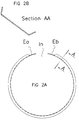
- La figure 2 représente le schéma du dispositif selon la figure 1 :
- 2.a -
- vue en plan ;
- 2.b -
- section.
- La figure 3 représente le dispositif de la figure 1 :
- 3.a -
- tel que fabriqué, libre de toute contrainte ;
- 3.b -
- en position de présentation d'insertion pour le montage dans la roue, soumis à une contrainte de serrage par des moyens non représentés ;
- 3.c -
- en position de montage dans la roue non représentée.
- FIG. 1 represents a section of the wheel through an axial plane on which there is a projection of the valve, the wheel being provided with an example of a device according to the invention.
- FIG. 2 represents the diagram of the device according to FIG. 1:
- 2.a -
- plan view;
- 2.b -
- section.
- FIG. 3 represents the device of FIG. 1:
- 3.a -
- as manufactured, free from all constraints;
- 3.b -
- in the insertion presentation position for mounting in the wheel, subjected to a clamping stress by means not shown;
- 3.c -
- in the mounting position in the wheel not shown.
La dénomination courante de la roue concernée selon les nomenclatures ETRTO (European Tire Rim Technical Organisation) ou les normes ISO est :
Le profilé peut être réalisé dans une bande de tôle d'acier ordinaire ou d'acier à ressort, dont les dimensions sont proches des suivantes :
Epaisseur : 1,5 mm, Longueur : 1643 mm, Largeur : 81,4 mm mise sous forme d'un anneau en la soudant bout à bout. L'anneau est ensuite roulé pour lui donner un profil en forme de U aplati défini figure 2.b de diamètre de fabrication sous le creux de 523 mm. On en supprime une longueur (In) d'environ 77 mm, pour obtenir un anneau brisé de forme sensiblement circulaire d'un diamètre de fabrication interne (Dfi) d'environ 523 mm, de longueur développée de 1566 mm, laissant entre ses extrémités un intervalle d'environ 77 mm, (In Figure 2.a). A chaque extrémité (Ea, Eb), les ailes du profilé sont supprimées sur 20 à 35 mm, (Figures 2.a, 3.a) ce qui permet de prévoir le passage de la valve (V Figure 3.c), et de faciliter le chevauchement de l'une des extrémités (par exemple Eb) sous l'autre (Ea) de façon à refermer l'anneau par une déformation élastique, (Figure 3.b) pour lui conférer un diamètre local interne de présentation (Dpi) pour l'insertion dans la roue d'environ 472 mm, et un diamètre externe inférieur à 494 mm, ce qui lui permet de passer sous le fond de gorge de la jante considérée.The profile can be produced from a strip of ordinary steel sheet or spring steel, the dimensions of which are close to the following:
Thickness: 1.5 mm, Length: 1643 mm, Width: 81.4 mm shaped into a ring by welding it end to end. The ring is then rolled to give it a flattened U-shaped profile defined in Figure 2.b with a manufacturing diameter under the hollow of 523 mm. We remove a length (In) of about 77 mm, to obtain a broken ring of substantially circular shape with an internal manufacturing diameter (Dfi) of about 523 mm, with a developed length of 1566 mm, leaving between its ends an interval of approximately 77 mm, (In Figure 2.a). At each end (Ea, Eb), the wings of the profile are removed over 20 to 35 mm, (Figures 2.a, 3.a) which makes it possible to provide for the passage of the valve (V Figure 3.c), and to facilitate the overlapping of one of the ends (for example Eb) under the other (Ea) so as to close the ring by an elastic deformation, (Figure 3.b) to give it an internal local presentation diameter ( Dpi) for insertion into the wheel of approximately 472 mm, and an external diameter less than 494 mm, which allows it to pass under the groove bottom of the rim considered.
Pour faciliter le maintien de la position de présentation, chaque extrémité Ea, Eb peut être percée d'un trou permettant le passage d'une pièce de blocage provisoire qui facilite la manipulation de l'anneau refermé. Celui-ci peut alors pénétrer dans la roue par un déplacement axial dans le volume V1, en prenant soin de disposer l'évidement Ea sous la valve. On peut dès lors relâcher les forces maintenant l'anneau en position fermée. L'élasticité de l'anneau provoquant l'écartement de ses extrémités, il atteint sa position de montage (Figure 3.c) pour laquelle les extrémités Ea, Eb sont sensiblement en contact face à face. L'anneau présente alors encore une déformation élastique qui le contraint à un diamètre de montage interne (Dmi) d'environ 498 mm. Les forces élastiques correspondantes plaquent l'anneau sur la surface interne du volume V1 de la roue et le maintiennent en position de protection du volume interne V1 et de la valve.To facilitate the maintenance of the presentation position, each end Ea, Eb can be pierced with a hole allowing the passage of a temporary blocking piece which facilitates the handling of the closed ring. The latter can then enter the wheel by an axial displacement in the volume V1, taking care to arrange the recess Ea under the valve. We can therefore release the forces holding the ring in the closed position. The elasticity of the ring causing the separation of its ends, it reaches its mounting position (Figure 3.c) for which the ends Ea, Eb are substantially in contact face to face. The ring then still has an elastic deformation which constrains it to an internal mounting diameter (Dmi) of approximately 498 mm. The corresponding elastic forces place the ring on the internal surface of the volume V1 of the wheel and keep it in the position of protection of the internal volume V1 and of the valve.
En cas de besoin, on peut ajouter un blocage supplémentaire de la rotation de l'anneau en munissant une aile du profilé d'au moins une patte la prolongeant dans l'un des ajours du disque de roue. Dans le cas de ce type de fabrication métallique, il est avantageux de protéger les parties du profilé au contact direct avec la jante ou le disque par une matière moins dure (plastique, caoutchouc) pour éviter de blesser le revêtement de surface des roues. Dans le même but, il peut être intéressant de recourber les bords de l'anneau de façon à faire porter le dispositif sur la roue par une surface courbe, et non par une arête.If necessary, an additional blocking of the rotation of the ring can be added by providing a wing of the profile with at least one lug extending it in one of the openings of the wheel disc. In the case of this type of metal fabrication, it is advantageous to protect the parts of the profile in direct contact with the rim or the disc with a less hard material (plastic, rubber) to avoid injuring the surface coating of the wheels. For the same purpose, it may be advantageous to bend the edges of the ring so as to bring the device to the wheel by a curved surface, and not by an edge.
Claims (14)
Applications Claiming Priority (2)
| Application Number | Priority Date | Filing Date | Title |
|---|---|---|---|
| FR9412263A FR2725665A1 (en) | 1994-10-12 | 1994-10-12 | METHOD AND DEVICE FOR PROTECTING THE ELEMENTS OF VEHICLE WHEELS |
| FR9412263 | 1994-10-12 |
Publications (2)
| Publication Number | Publication Date |
|---|---|
| EP0706902A1 true EP0706902A1 (en) | 1996-04-17 |
| EP0706902B1 EP0706902B1 (en) | 1999-01-13 |
Family
ID=9467848
Family Applications (1)
| Application Number | Title | Priority Date | Filing Date |
|---|---|---|---|
| EP95115607A Expired - Lifetime EP0706902B1 (en) | 1994-10-12 | 1995-10-04 | Process and apparatus for protecting parts of vehicle wheels |
Country Status (5)
| Country | Link |
|---|---|
| EP (1) | EP0706902B1 (en) |
| AT (1) | ATE175631T1 (en) |
| DE (1) | DE69507241T2 (en) |
| ES (1) | ES2128626T3 (en) |
| FR (1) | FR2725665A1 (en) |
Cited By (2)
| Publication number | Priority date | Publication date | Assignee | Title |
|---|---|---|---|---|
| WO2006019749A1 (en) * | 2004-07-14 | 2006-02-23 | Bendix Spicer Foundation Brake Llc | Wheel valve stem shield for air disc brake applications |
| EP1982852A1 (en) * | 2007-04-17 | 2008-10-22 | Bendix Spicer Foundation Brake LLC | Wrong Wheel Warning Sensor |
Citations (3)
| Publication number | Priority date | Publication date | Assignee | Title |
|---|---|---|---|---|
| EP0032747A1 (en) * | 1980-01-22 | 1981-07-29 | Georg Fischer Aktiengesellschaft | Single-piece moulded drop center rim for vehicle wheel |
| US4407348A (en) * | 1981-01-23 | 1983-10-04 | Caterpillar Tractor Co. | Multi-piece wheel structure |
| DE4332894A1 (en) * | 1993-09-22 | 1995-03-30 | Mannesmann Ag | Valve protection for disc wheels with pneumatic tyres |
-
1994
- 1994-10-12 FR FR9412263A patent/FR2725665A1/en active Pending
-
1995
- 1995-10-04 AT AT95115607T patent/ATE175631T1/en not_active IP Right Cessation
- 1995-10-04 DE DE69507241T patent/DE69507241T2/en not_active Expired - Fee Related
- 1995-10-04 EP EP95115607A patent/EP0706902B1/en not_active Expired - Lifetime
- 1995-10-04 ES ES95115607T patent/ES2128626T3/en not_active Expired - Lifetime
Patent Citations (3)
| Publication number | Priority date | Publication date | Assignee | Title |
|---|---|---|---|---|
| EP0032747A1 (en) * | 1980-01-22 | 1981-07-29 | Georg Fischer Aktiengesellschaft | Single-piece moulded drop center rim for vehicle wheel |
| US4407348A (en) * | 1981-01-23 | 1983-10-04 | Caterpillar Tractor Co. | Multi-piece wheel structure |
| DE4332894A1 (en) * | 1993-09-22 | 1995-03-30 | Mannesmann Ag | Valve protection for disc wheels with pneumatic tyres |
Cited By (2)
| Publication number | Priority date | Publication date | Assignee | Title |
|---|---|---|---|---|
| WO2006019749A1 (en) * | 2004-07-14 | 2006-02-23 | Bendix Spicer Foundation Brake Llc | Wheel valve stem shield for air disc brake applications |
| EP1982852A1 (en) * | 2007-04-17 | 2008-10-22 | Bendix Spicer Foundation Brake LLC | Wrong Wheel Warning Sensor |
Also Published As
| Publication number | Publication date |
|---|---|
| ES2128626T3 (en) | 1999-05-16 |
| ATE175631T1 (en) | 1999-01-15 |
| DE69507241D1 (en) | 1999-02-25 |
| EP0706902B1 (en) | 1999-01-13 |
| DE69507241T2 (en) | 1999-06-10 |
| FR2725665A1 (en) | 1996-04-19 |
Similar Documents
| Publication | Publication Date | Title |
|---|---|---|
| FR2993500A1 (en) | TREAD TIRE FOR HEAVY-DUTY AND TIRE ENGINE AXLE TIRES | |
| FR3027256A1 (en) | DEVICE FOR PROTECTING A TIRE FLANK | |
| FR2925373A1 (en) | METHOD FOR MANUFACTURING A HYBRID STRUCTURAL PART, AND PIECE THUS OBTAINED | |
| EP2849956B1 (en) | Improved noise reducing device for a tire | |
| CH624890A5 (en) | ||
| EP0755807A2 (en) | Commercial vehicle wheel with valve, which opens outside the disk | |
| FR2492492A1 (en) | METHOD AND DEVICE FOR SOUNDPROOFING A METAL WHEEL | |
| CA1253535A (en) | One piece rim so made as to capture and hold the beat of a tire on its seat, and mounting process of the tire body on the rim | |
| FR2698823A1 (en) | Improved ring device for run flat. | |
| CA2300506A1 (en) | Tread sculpture and mould | |
| EP4185528A1 (en) | Heat shield assembly | |
| EP2900487B1 (en) | Improved device against resonance sound for a tire | |
| EP0706902B1 (en) | Process and apparatus for protecting parts of vehicle wheels | |
| FR2744953A1 (en) | WHEEL WHEEL WITH RAYS TO BE EQUIPPED WITH A PNEUMATIC WITHOUT BED ROOM, AND WHEEL WITH RAYS SO EQUIPPED | |
| FR2827548A1 (en) | Tubeless tire and wheel rim assembly, especially for bicycles, has stepped rim making contact with tire bead at two or more points | |
| CA2603272C (en) | Locking ring in an assembly for mounting a tyre on a vehicle hub | |
| EP0155210B1 (en) | Discontinuous inflatable inserts | |
| EP0557164A1 (en) | Bead retainer for pneumatique tyre | |
| EP3727883A1 (en) | Assembly for a tyre | |
| CA2124412C (en) | Air valve and use for inflating tires with sealing ring | |
| FR2969237A1 (en) | Drive wheel suspension device for front running gear of motor vehicle, has flexible retaining ring made of flexible plastic and positioned in support between protection ring and hub support, where protection ring protects wheel bearing | |
| FR2653384A1 (en) | DEVICE FOR WHEEL, ROLLER, ROLLER, OR THE LIKE. | |
| WO2001070542A1 (en) | Flap accessory | |
| EP3695990B1 (en) | Inflator tip for self-repairing tyre | |
| CA2217467A1 (en) | Run-flat device for motor vehicles, in particular touring vehicles |
Legal Events
| Date | Code | Title | Description |
|---|---|---|---|
| PUAI | Public reference made under article 153(3) epc to a published international application that has entered the european phase |
Free format text: ORIGINAL CODE: 0009012 |
|
| AK | Designated contracting states |
Kind code of ref document: A1 Designated state(s): AT DE ES FR GB IT SE |
|
| 17P | Request for examination filed |
Effective date: 19961017 |
|
| GRAG | Despatch of communication of intention to grant |
Free format text: ORIGINAL CODE: EPIDOS AGRA |
|
| 17Q | First examination report despatched |
Effective date: 19980108 |
|
| GRAG | Despatch of communication of intention to grant |
Free format text: ORIGINAL CODE: EPIDOS AGRA |
|
| GRAH | Despatch of communication of intention to grant a patent |
Free format text: ORIGINAL CODE: EPIDOS IGRA |
|
| GRAH | Despatch of communication of intention to grant a patent |
Free format text: ORIGINAL CODE: EPIDOS IGRA |
|
| GRAA | (expected) grant |
Free format text: ORIGINAL CODE: 0009210 |
|
| AK | Designated contracting states |
Kind code of ref document: B1 Designated state(s): AT DE ES FR GB IT SE |
|
| PG25 | Lapsed in a contracting state [announced via postgrant information from national office to epo] |
Ref country code: SE Free format text: THE PATENT HAS BEEN ANNULLED BY A DECISION OF A NATIONAL AUTHORITY Effective date: 19990113 Ref country code: AT Free format text: LAPSE BECAUSE OF FAILURE TO SUBMIT A TRANSLATION OF THE DESCRIPTION OR TO PAY THE FEE WITHIN THE PRESCRIBED TIME-LIMIT Effective date: 19990113 |
|
| REF | Corresponds to: |
Ref document number: 175631 Country of ref document: AT Date of ref document: 19990115 Kind code of ref document: T |
|
| REF | Corresponds to: |
Ref document number: 69507241 Country of ref document: DE Date of ref document: 19990225 |
|
| GBT | Gb: translation of ep patent filed (gb section 77(6)(a)/1977) |
Effective date: 19990218 |
|
| ITF | It: translation for a ep patent filed | ||
| REG | Reference to a national code |
Ref country code: ES Ref legal event code: FG2A Ref document number: 2128626 Country of ref document: ES Kind code of ref document: T3 |
|
| PLBE | No opposition filed within time limit |
Free format text: ORIGINAL CODE: 0009261 |
|
| STAA | Information on the status of an ep patent application or granted ep patent |
Free format text: STATUS: NO OPPOSITION FILED WITHIN TIME LIMIT |
|
| 26N | No opposition filed | ||
| REG | Reference to a national code |
Ref country code: GB Ref legal event code: IF02 |
|
| PGFP | Annual fee paid to national office [announced via postgrant information from national office to epo] |
Ref country code: GB Payment date: 20030929 Year of fee payment: 9 |
|
| PGFP | Annual fee paid to national office [announced via postgrant information from national office to epo] |
Ref country code: FR Payment date: 20031009 Year of fee payment: 9 |
|
| PGFP | Annual fee paid to national office [announced via postgrant information from national office to epo] |
Ref country code: DE Payment date: 20031010 Year of fee payment: 9 |
|
| PGFP | Annual fee paid to national office [announced via postgrant information from national office to epo] |
Ref country code: ES Payment date: 20031017 Year of fee payment: 9 |
|
| PG25 | Lapsed in a contracting state [announced via postgrant information from national office to epo] |
Ref country code: GB Free format text: LAPSE BECAUSE OF NON-PAYMENT OF DUE FEES Effective date: 20041004 |
|
| PG25 | Lapsed in a contracting state [announced via postgrant information from national office to epo] |
Ref country code: ES Free format text: LAPSE BECAUSE OF NON-PAYMENT OF DUE FEES Effective date: 20041005 |
|
| PG25 | Lapsed in a contracting state [announced via postgrant information from national office to epo] |
Ref country code: DE Free format text: LAPSE BECAUSE OF NON-PAYMENT OF DUE FEES Effective date: 20050503 |
|
| GBPC | Gb: european patent ceased through non-payment of renewal fee |
Effective date: 20041004 |
|
| PG25 | Lapsed in a contracting state [announced via postgrant information from national office to epo] |
Ref country code: FR Free format text: LAPSE BECAUSE OF NON-PAYMENT OF DUE FEES Effective date: 20050630 |
|
| REG | Reference to a national code |
Ref country code: FR Ref legal event code: ST |
|
| PG25 | Lapsed in a contracting state [announced via postgrant information from national office to epo] |
Ref country code: IT Free format text: LAPSE BECAUSE OF NON-PAYMENT OF DUE FEES;WARNING: LAPSES OF ITALIAN PATENTS WITH EFFECTIVE DATE BEFORE 2007 MAY HAVE OCCURRED AT ANY TIME BEFORE 2007. THE CORRECT EFFECTIVE DATE MAY BE DIFFERENT FROM THE ONE RECORDED. Effective date: 20051004 |
|
| REG | Reference to a national code |
Ref country code: ES Ref legal event code: FD2A Effective date: 20041005 |