EP0706932A1 - Fahrradständer - Google Patents
Fahrradständer Download PDFInfo
- Publication number
- EP0706932A1 EP0706932A1 EP95114093A EP95114093A EP0706932A1 EP 0706932 A1 EP0706932 A1 EP 0706932A1 EP 95114093 A EP95114093 A EP 95114093A EP 95114093 A EP95114093 A EP 95114093A EP 0706932 A1 EP0706932 A1 EP 0706932A1
- Authority
- EP
- European Patent Office
- Prior art keywords
- support
- leg
- stand according
- holder
- bicycle
- Prior art date
- Legal status (The legal status is an assumption and is not a legal conclusion. Google has not performed a legal analysis and makes no representation as to the accuracy of the status listed.)
- Granted
Links
- 230000002787 reinforcement Effects 0.000 abstract 1
- 238000004140 cleaning Methods 0.000 description 2
- 230000001154 acute effect Effects 0.000 description 1
- 230000005489 elastic deformation Effects 0.000 description 1
- XLYOFNOQVPJJNP-UHFFFAOYSA-N water Substances O XLYOFNOQVPJJNP-UHFFFAOYSA-N 0.000 description 1
Images




Classifications
-
- B—PERFORMING OPERATIONS; TRANSPORTING
- B62—LAND VEHICLES FOR TRAVELLING OTHERWISE THAN ON RAILS
- B62H—CYCLE STANDS; SUPPORTS OR HOLDERS FOR PARKING OR STORING CYCLES; APPLIANCES PREVENTING OR INDICATING UNAUTHORIZED USE OR THEFT OF CYCLES; LOCKS INTEGRAL WITH CYCLES; DEVICES FOR LEARNING TO RIDE CYCLES
- B62H3/00—Separate supports or holders for parking or storing cycles
- B62H3/02—Separate supports or holders for parking or storing cycles involving means for gripping the cycle by the handlebars or by the upper part of the frame
Definitions
- the invention relates to a bicycle stand according to the preamble of claim 1.
- a known bicycle stand of this type has an L-shaped leg, on the free horizontal leg of which a holder provided with a clamping piece is fastened.
- a center tube of a bicycle can be fastened in its clamping opening.
- the invention has for its object to design a bicycle stand of this type so that the parking space available in each case can be optimally used.
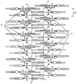
- the bicycle stand 1 shown in the drawings is suitable for parking two bicycles 2 and 3 and can be arranged with a plurality of identical stands in a row next to one another (FIG. 6) and also in a row one behind the other (FIG. 7). It is therefore particularly suitable for covered parking spaces where there is relatively little and therefore expensive parking space. Such parking lots are usually available in public buildings, such as schools, bathrooms and the like, where space can be optimally used with these bike racks.
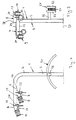
- the bicycle stand 1 has an L-shaped leg 4, which is preferably made of a tube.
- the leg 4 is anchored to the floor with the longer leg 5, while the other, somewhat shorter leg 6 runs horizontally and carries two holders 9 and 10 for the bicycles 2 and 3.
- the holders 9 and 10 are fastened to supports 7 and 8 which project transversely from the leg 6 and are directed in opposite directions to one another.
- the holders 9 and 10 are provided in a manner known per se with a clamping part 11, 12 which is held with a plug part (not shown) in a pipe section 21, 22 projecting transversely from the carrier 7, 8.
- the clamping parts 11, 12 have mutually opposite clamping legs 13, 14 and 15, 16, which limit a clamping receptacle 17, 18 for a central or seat tube 19, 20 of the bicycles 2, 3.
- the holders 9, 10 are arranged inclined on the support leg 4 such that their clamping legs 13, 14; 15, 16 run perpendicular to the seat tube 19, 20.
- the bicycles can be conveniently inserted or removed again in the clamping parts 11, 12 for parking directly in the direction of travel.
- the center tubes 19, 20 of the bicycles 2, 3 as a result of elastic deformation of the clamping legs 13 to 16 held clamped.
- the holders 9 and 10 lie on different sides of the horizontal leg 6 and at different heights and offset from one another.
- the holder 9 is fastened to the carrier 7, which has a support arm 23 with a stiffening strip 25 and the pipe section 21.
- the support arm 23 is about half as long as the horizontal leg 6 of the leg 4; its width corresponds approximately to the tube diameter of the main leg.
- the ends 30 and 36 of the support arm 23 are rounded in the shape of a part circle.
- the pipe section 21 is preferably welded at one end 30.
- the stiffening strip 25 rests on the upper edge 31 of the support arm 23 and extends perpendicular to the support arm 23.
- the stiffening strip 25 tapers from the supporting leg leg 6.
- the free end 39 of the stiffening strip 25 extends close to the pipe section 21.
- the carrier 7 lies essentially in the region below the supporting leg leg 6.
- the other support 8 has a support arm 24 which is approximately half as long as the support arm 23, which is of the same design and is attached at one end to the front side of the leg 6.
- the pipe section 22 is attached, which projects perpendicularly from the support arm 24.
- a stiffening strip 26 is fastened, which is continuously tapered towards its end facing away from the leg 6. The wider end 33 of the stiffening strip 26 rests on the upper side 34 of the leg 6, while its narrow end 35 extends up to the height of the pipe section 22 is sufficient, but at a distance from the free end 32 of the support arm 24.
- the two support arms 23, 24 are each formed in a strip shape and arranged upright.
- the holders 9, 10 extend in the same directions and are parallel to one another (FIGS. 4 and 5).
- a securing part 40 or 41 for the associated bicycle is provided on each support arm 23, 24.
- the securing parts preferably consist of rings, the one ring in an opening 42 or 43 of the support arm 23; 24 is attached.
- On the other ring 44, 45, a security chain, a wire rope, a padlock or the like can be attached to theft protection of the bicycle, so that the bicycles can be properly secured. Since the securing parts 40, 41 are provided on both sides of the stand 4 and to the side of the bicycle to be secured, such securing chains, wire cables or the like can be conveniently attached from a gear formed between adjacent bicycle stands 1.
- the inclination of the holders 9, 10 or their clamping parts 11, 12 is achieved at an angle of 90 ° to the central tube 19, 20 of the bicycles 2, 3 in that the tube pieces 21, 22 are chamfered Face 46, 47 are attached to the support arms 23 and 24, which are each in a vertical plane in the installed position.
- the axis of the pipe sections 21, 22 lies at an acute angle to the horizontal leg 6 of the supporting leg 4.
- the asymmetrical arrangement of the holders 9, 10 in different positions and at different heights to the supporting leg 4 ensures that the pedals 48 of the two bicycles 2, 3 held on the same pillar 4 are arranged at a distance from one another and one behind the other so that they do not impede one another. Since the holder 10 is displaced upwards in relation to the holder 9, this free space for the pedals is increased.
- the raised front wheel 50 is supported by a support 51 which is provided on the same side of the supporting leg 4 as the holder 10. It is bent in the shape of a part circle and has edge-side pipe bends 52 and 53 (FIGS. 2 to 5), between which a correspondingly curved grid 54 is fastened as a contact surface.
- the support 51 rests on a pipe piece 55 projecting perpendicularly from the vertical leg 5 of the supporting leg 4, at the end of which an upwardly projecting stop 56 is fastened.
- the outer pipe bend 52 bears against it.
- the support 51 is attached to the vertical leg 5 at such a distance from the floor 57 that the bicycle 3 is in the parked position (FIG.
- the drive surface 54 of the support 51 which is designed as a grid, ensures problem-free cleaning of the support. Water, dirt and the like can get down through them. Between the two pipe elbows 52 and 53, the wheel is guided securely when it runs onto the support, since the pipe sections projecting beyond the grid 54 serve as a guide for the front wheel. Due to the open design of the surface 54 of the support 51, cleaning is not only easy, but largely avoided because dirt cannot even get stuck.
- a plurality of stands 1 are advantageously arranged in a row next to one another in public parking lots where little space is available, each having the same distance from one another, which is somewhat larger than the maximum width of the handlebars 57
- the distance between the two bicycles 2 and 3 is preferably 35 cm, so that the distance between adjacent bicycles 2 or the second bicycles 3 supported on the support 51 is 70 cm, measured in each case between the longitudinal center plane of the bicycle.
- Such rows of bicycle stands can also be arranged in any length and in any number one behind the other, as shown in FIG. 7. Even with such an arrangement, it is possible to park the bicycles without any problems, and the largest possible number of bicycles can be parked in a confined space.
Landscapes
- Engineering & Computer Science (AREA)
- Mechanical Engineering (AREA)
- Steering Devices For Bicycles And Motorcycles (AREA)
- Fittings On The Vehicle Exterior For Carrying Loads, And Devices For Holding Or Mounting Articles (AREA)
- Axle Suspensions And Sidecars For Cycles (AREA)
- Automatic Cycles, And Cycles In General (AREA)
- Handcart (AREA)
Abstract
Description
- Die Erfindung betrifft einen Fahrradständer nach dem Oberbegriff des Anspruches 1.
- Ein bekannter Fahrradständer dieser Art weist ein L-förmig gebogenes Standbein auf, an dessen freiem Horizontalschenkel ein mit einem Klemmstück versehener Halter befestigt ist. In seiner Klemmöffnung kann ein Mittelrohr eines Fahrrades befestigt werden. Auf Parkplätzen können mehrere solcher Ständer im Abstand voneinander angeordnet werden.
- Der Erfindung liegt die Aufgabe zugrunde, einen Fahrradständer dieser Art so auszubilden, daß die jeweils zur Verfügung stehende Parkfläche optimal ausgenutzt werden kann.
- Diese Aufgabe wird bei einem Fahrradständer der gattungsbildenden Art erfindungsgemäß mit den kennzeichnenden Merkmalen des Anspruches 1 gelöst.
- Infolge der zueinander versetzten Lage der Halter können Fahrräder eng benachbart und auf Lücke zueinander geparkt werden, so daß die jeweilige Parkfläche optimal ausgenutzt werden kann. Trotz dieser dichten Anordnung der Fahrräder an den Ständern ist zwischen den Fahrradständern bzw. Fahrrädern noch so viel Freiraum vorhanden, daß das Fahrrad bequem am Ständer geparkt bzw. wieder von ihm entfernt werden kann.
- Weitere Merkmale der Erfindung ergeben sich aus den weiteren Ansprüchen, der Beschreibung und den Zeichnungen.
- Die Erfindung wird nachstehend anhand eines in den Zeichungen dargestellten Ausführungsbeispieles näher beschrieben. Es zeigt:
- Fig. 1
- in Seitenansicht einen erfindungsgemäßen Fahrradständer mit zwei daran geparkten Fahrrädern,
- Fig. 2
- den Ständer nach Fig. 1 in perspektivischer und vergrößerter Darstellung,
- Fig. 3
- in einer Ansicht gemäß Pfeil II in Fig. 2 den erfindungsgemäßen Ständer,
- Fig. 4
- den Ständer gemäß Fig. 3 in Seitenansicht,
- Fig. 5
- den Ständer nach Fig. 3 in Draufsicht,
- Fig. 6
- in Draufsicht eine Vielzahl erfindungsgemäßer Fahrradständer, die mit Abstand nebeneinander angeordnet sind und an denen jeweils zwei Fahrräder geparkt sind,
- Fig. 7
- eine Darstellung entsprechend Fig. 6, wobei zwei Reihen von Fahrradständern hintereinander angeordnet sind.
- Der in den Zeichnungen dargestellte Fahrradständer 1 eignet sich zum Parken zweier Fahrräder 2 und 3 und kann mit einer Vielzahl gleicher Ständer in Reihe nebeneinander (Fig. 6) und auch in Reihen hintereinander (Fig. 7) angeordnet werden. Somit eignet er sich besonders für überdachte Parkplätze, bei denen relativ wenig und dadurch teure Parkflächen vorhanden sind. Solche Parkplätze sind meist bei öffentlichen Gebäuden, wie Schulen, Bädern und dergleichen, vorhanden, wo mit diesen Fahrradständern der Raum optimal ausgenutzt werden kann.
- Der Fahrradständer 1 hat ein L-förmig gebogenes Standbein 4, das vorzugsweise aus einem Rohr hergestellt ist. Mit dem längeren Schenkel 5 ist das Standbein 4 am Boden verankert, während der andere, etwas kürzere Schenkel 6 horizontal verläuft und zwei Halter 9 und 10 für die Fahrräder 2 und 3 trägt. Die Halter 9 und 10 sind an Trägern 7 und 8 befestigt, die quer vom Schenkel 6 abstehen und entgegengesetzt zueinander gerichtet sind.
- Die Halter 9 und 10 sind in an sich bekannter Weise mit einem Klemmteil 11, 12 versehen, das mit einem (nicht dargestellten) Steckteil in einem quer vom Träger 7, 8 abstehenden Rohrstück 21, 22 gehalten wird. Die Klemmteile 11, 12 haben einander gegenüberliegende Klemmschenkel 13, 14 bzw. 15, 16, die eine Klemmaufnahme 17, 18 für ein Mittel- bzw. Sitzrohr 19, 20 der Fahrräder 2, 3 begrenzen. Die Halter 9, 10 sind am Standbein 4 derart geneigt angeordnet, daß ihre Klemmschenkel 13, 14; 15, 16 zum Sitzrohr 19, 20 senkrecht verlaufen. Dadurch können die Fahrräder zum Parken direkt in Fahrtrichtung bequem in die Klemmteile 11, 12 eingeschoben bzw. wieder entnommen werden. In den Klemmaufnahmen 17, 18 werden die Mittelrohre 19, 20 der Fahrräder 2, 3 infolge der elastischen Verformung der Klemmschenkel 13 bis 16 klemmend gehalten.
- Wie insbesondere die Fig. 2 bis 5 zeigen, liegen die Halter 9 und 10 auf verschiedenen Seiten des Horizontalschenkels 6 und auf verschiedenen Höhen sowie versetzt zueinander. Der Halter 9 ist am Träger 7 befestigt, der einen Tragarm 23 mit einer Versteifungsleiste 25 sowie dem Rohrstück 21 aufweist. Der Tragarm 23 ist etwa halb so lang wie der Horizontalschenkel 6 des Standbeines 4; seine Breite entspricht etwa dem Rohrdurchmesser des Standbeines. Die Enden 30 und 36 des Tragarmes 23 sind teilkreisförmig abgerundet. Das Rohrstück 21 ist an dem einen Ende 30 vorzugsweise verschweißt. Auf dem oberen Rand 31 des Tragarmes 23 liegt die Versteifungsleiste 25 auf und erstreckt sich senkrecht zum Tragarm 23. Die Versteifungsleiste 25 verjüngt sich vom Standbeinschenkel 6 aus. Das freie Ende 39 der Versteifungsleiste 25 reicht bis nahe an das Rohrstück 21. Wie Fig.3 zeigt, liegt der Träger 7 im wesentlichen im Bereich unterhalb des Standbeinschenkels 6.
- Der andere Träger 8 hat einen Tragarm 24, der etwa halb so lang ist wie der im übrigen gleich ausgebildete Tragarm 23 und mit seinem einen Ende auf der Stirnseite des Standbeinschenkels 6 befestigt ist. Am anderen Tragarmende ist das Rohrstück 22 befestigt, das senkrecht vom Tragarm 24 absteht. An der vom Rohrstück 22 abgewandten Seite des Tragarmes 24 ist eine Versteifungsleiste 26 befestigt, die in Richtung auf ihr vom Standbeinschenkel 6 abgewandtes Ende stetig verjüngt ausgebildet ist. Die Versteifungsleiste 26 liegt mit ihrem breiteren Ende 33 auf der Oberseite 34 des Standbeinschenkels 6 auf, während ihr schmales Ende 35 bis in Höhe des Rohrstückes 22 reicht, jedoch vom freien Ende 32 des Tragarmes 24 Abstand hat.
- Die beiden Tragarme 23, 24 sind jeweils leistenförmig ausgebildet und hochkant angeordnet. Die Halter 9, 10 erstrecken sich in gleiche Richtungen und liegen parallel zueinander (Fig. 4 und 5).
- An jedem Tragarm 23, 24 ist ein Sicherungsteil 40 bzw. 41 für das zugehörige Fahrrad vorgesehen. Die Sicherungteile bestehen vorzugsweise aus Ringen, wobei der eine Ring in eine Öffnung 42 bzw. 43 des Tragarmes 23; 24 eingehängt ist. Am anderen Ring 44, 45 kann eine Sicherungskette, ein Drahtseil, ein Bügelschloß oder dergleichen zur Diebstahlsicherung des Fahrrads befestigt werden, so daß die Fahrräder einwandfrei gesichert werden können. Da die Sicherungsteile 40, 41 beiderseits des Ständers 4 und seitlich von dem zu sichernden Fahrrad vorgesehen sind, können solche Sicherungsketten, Drahtseile oder dergleichen bequem von einem zwischen einander benachbarten Fahrradständern 1 gebildeten Gang aus befestigt werden.
- Wie insbesondere Fig. 4 zeigt, wird die Neigung der Halter 9, 10 bzw. ihrer Klemmteile 11, 12 mit einem Winkel von 90° zum Mittelrohr 19, 20 der Fahrräder 2, 3 dadurch erreicht, daß die Rohrstücke 21, 22 mit einer abgeschrägten Stirnseite 46, 47 an den Tragarmen 23 bzw. 24 befestigt sind, die in der Einbaulage jeweils in einer Vertikalebene liegen. Die Achse der Rohrstücke 21, 22 liegt unter einem spitzen Winkel zum Horizontalschenkel 6 des Standbeines 4. Durch die asymmetrische Anordnung der Halter 9, 10 in unterschiedlichen Lagen und in unterschiedlicher Höhe zum Standbein 4 wird erreicht, daß die Pedale 48 der beiden an demselben Standbein 4 gehaltenen Fahrräder 2, 3 mit Abstand voneinander und hintereinander angeordnet sind, so daß sie einander gegenseitig nicht behindern. Da der Halter 10 in Höhenrichtung gegenüber dem Halter 9 nach oben versetzt ist, wird dieser Freiraum für die Pedale noch vergrößert.
- In der in Fig. 1 dargestellten, schräg nach oben gekippten Lage des Fahrrades 3 wird das angehobene Vorderrad 50 durch eine Stütze 51 abgestützt, die auf der gleichen Seite des Standbeines 4 wie der Halter 10 vorgesehen ist. Sie ist teilkreisförmig gebogen und hat randseitige Rohrbögen 52 und 53 (Fig. 2 bis 5), zwischen denen als Aufstandsfläche ein entsprechend gekrümmtes Gitter 54 befestigt ist. Die Stütze 51 liegt auf einem senkrecht vom Vertikalschenkel 5 des Standbeines 4 abstehenden Rohrstück 55 auf, an dessen Ende ein aufwärts ragender Anschlag 56 befestigt ist. An ihm liegt der äußere Rohrbogen 52 an. Die Stütze 51 ist in einem solchen Abstand vom Boden 57 am Vertikalschenkel 5 befestigt, daß das Fahrrad 3 in geparkter Stellung (Fig. 1) mit seinem Vorderrad 50 etwa auf der höchsten Stelle der bogenförmigen, aufwärts gekrümmten Stütze 51 steht. Beim Parken dient die Stütze 51 als Auffahrrampe, wobei der Lenker 58 des zweiten Fahrrades 3 über den Sattel 59 des ersten, bereits geparkten Fahrrades 2, ohne an diesem anzustoßen, angehoben wird.
- Durch die als Gitter ausgebildete Auffahrfläche 54 der Stütze 51 ist eine problemlose Reinigung der Stütze sichergestellt. Durch sie kann Wasser, Schmutz und dgl. nach unten gelangen. Zwischen den beiden Rohrbögen 52 und 53 ist das Rad beim Auffahren auf die Stütze sicher geführt, da die über das Gitter 54 überstehenden Rohrabschnitte hierbei als Führung für das Vorderrad dienen. Durch die offene Ausbildung der Fläche 54 der Stütze 51 ist eine Reinigung nicht nur einfach, sondern weitgehend vermieden, weil sich Schmutz gar nicht erst festsetzen kann.
- Wie Fig. 6 zeigt, wird vorteilhaft auf öffentlichen Parkplätzen, wo wenig Platz zur Verfügung steht, eine Vielzahl von Ständern 1 in Reihe nebeneinander angeordnet, wobei sie jeweils gleichen Abstand voneinander haben, der etwas größer ist als die maximale Breite der Lenker 57. Im Ausführungsbeispiel beträgt der Abstand zwischen den beiden Fahrrädern 2 und 3 vorzugsweise 35 cm, so daß der Abstand zwischen einander benachbarten Fahrrädern 2 bzw. den zweiten, auf der Stütze 51 abgestützten Fahrrädern 3 70 cm beträgt, jeweils gemessen zwischen den Fahrradlängsmittelebenen. Bei einer solchen Anordnung der Ständer ist gewährleistet, daß die Fahrräder problemlos nebeneinander und auf kleinstem Raum geparkt werden können, wobei die Fahrräder leicht zugänglich sind, um sie zu parken bzw. sie wieder vom Ständer abzunehmen oder auch um die Fahrräder gegen Diebstahl mittels der Sicherungsteile 47, 48 zu sichern. Solche Reihen von Fahrradständern können auch in beliebiger Länge und in beliebiger Anzahl mit Abstand hintereinander angeordnet werden, wie Fig. 7 zeigt. Auch bei einer solchen Anordnung ist das Parken der Fahrräder problemlos möglich, wobei auf engstem Raum eine größtmögliche Zahl von Fahrrädern geparkt werden kann.
Claims (11)
- Fahrradständer mit einem Standbein, an dem ein Halter für ein Fahrrad vorgesehen ist,
dadurch gekennzeichnet, daß am Ständer (4) mindestens ein weiterer Halter (9, 10) vorgesehen ist, und daß die beiden Halter (9, 10) in Höhen- und/oder Längsrichtung des Standbeines (4) versetzt zueinander angeordnet sind. - Ständer nach Anspruch 1,
dadurch gekennzeichnet, daß die Halter (9, 10) in entgegengesetzte Richtungen weisen und vorzugsweise an Trägern (7, 8) befestigt sind. - Ständer nach Anspruch 1 oder 2,
dadurch gekennzeichnet, daß der eine Halter (9) größeren Abstand vom Standbein (4), vorzugsweise einem horizontalen Schenkel (6) des Standbeines, hat als der andere Halter (10). - Ständer nach Anspruch 3,
dadurch gekennzeichnet, daß die Halter (9, 10) an einem vorzugsweise schräg nach unten geneigt angeordneten Rohrstück (21, 22) vorgesehen sind, das am Träger (7, 8) befestigt ist, der vorzugsweise einen plattenartigen, mit wenigstens einem Versteifungsteil (25, 26) versehenen Tragarm (23, 24) aufweist. - Ständer Anspruch 3 oder 4,
dadurch gekennzeichnet, daß der eine Träger (8) am freien Ende des horizontalen Schenkels (6) des Standbeines (4) und der andere Träger (7) vorzugsweise mit Abstand vom freien Ende des Horizontalschenkels (6) des Standbeines (4) vorgesehen ist. - Ständer nach einem der Ansprüche 1 bis 5,
dadurch gekennzeichnet, daß die Halter (9, 10) Klemmteile (11, 12) aufweisen, in denen Fahrräder (2, 3) mit ihren Mittel- bzw. Sitzrohren (19, 20) klemmend gehalten sind. - Ständer nach einem der Ansprüche 1 bis 6,
dadurch gekennzeichnet, daß an einem Vertikalschenkel (5) des Standbeines (4) an dessen einer Seite mit Abstand vom Boden (57) eine Stütze (51) vorgesehen ist, die vorzugsweise eine Auffahrrampe für ein Vorderrad eines Fahrrades (3) bildet. - Ständer nach Anspruch 7,
dadurch gekennzeichnet, daß die Stütze (51) auf derselben Seite wie der mit kleinerem seitlichem Abstand vom Standbein (4) vorgesehene Halter (10) liegt, und daß die vorzugsweise annähernd halbkreisförmig verlaufende Stütze (51) auf einem Arm (55) angeordnet ist und vom Standbein (4) größeren Abstand hat als der Halter (10). - Ständer nach Anspruch 7 oder 8,
dadurch gekennzeichnet, daß die Stütze (51) zwei mit Abstand voneinander liegende seitliche Rohrbögen (52, 53) aufweist, die über eine vorzugsweise aus Gittermaterial bestehende Auflagefläche (54) für das Rad (55) miteinander verbunden sind, und daß vorzugsweise der Abstand der Rohrabschnitte (52, 53) voneinander größer ist als die Breite des Vorderrades (55) des Fahrrades (3). - Ständer nach einem der Ansprüche 7 bis 9,
dadurch gekennzeichnet, daß die Stütze (51) mit ihrem äußeren Rohrbogen (52) an einem Anschlag (56) anliegt. - Ständer nach einem der Ansprüche 4 bis 10,
dadurch gekennzeichnet, daß an den Tragarmen (23, 24) der Träger (7, 8) mindestens ein Sicherungsteil (40, 41), vorzugsweise mindestens ein Sicherungsring, befestigt ist.
Applications Claiming Priority (2)
| Application Number | Priority Date | Filing Date | Title |
|---|---|---|---|
| DE9416533U DE9416533U1 (de) | 1994-10-14 | 1994-10-14 | Fahrradständer |
| DE9416533U | 1994-10-14 |
Publications (2)
| Publication Number | Publication Date |
|---|---|
| EP0706932A1 true EP0706932A1 (de) | 1996-04-17 |
| EP0706932B1 EP0706932B1 (de) | 1998-11-25 |
Family
ID=6914872
Family Applications (1)
| Application Number | Title | Priority Date | Filing Date |
|---|---|---|---|
| EP95114093A Expired - Lifetime EP0706932B1 (de) | 1994-10-14 | 1995-09-08 | Fahrradständer |
Country Status (3)
| Country | Link |
|---|---|
| EP (1) | EP0706932B1 (de) |
| AT (1) | ATE173691T1 (de) |
| DE (2) | DE9416533U1 (de) |
Cited By (1)
| Publication number | Priority date | Publication date | Assignee | Title |
|---|---|---|---|---|
| WO2018075729A1 (en) * | 2016-10-19 | 2018-04-26 | Olinger Jeffrey Richard | High-density bike rack system |
Families Citing this family (4)
| Publication number | Priority date | Publication date | Assignee | Title |
|---|---|---|---|---|
| DE29614368U1 (de) * | 1996-08-20 | 1996-10-02 | Eisen- Und Drahtwerk Erlau Ag, 73431 Aalen | Ständer für Fahrräder |
| DE29717209U1 (de) | 1997-09-26 | 1997-11-06 | Eisen- Und Drahtwerk Erlau Ag, 73431 Aalen | Fahrradständer |
| FR2774651B1 (fr) * | 1998-02-10 | 2000-03-10 | Claude Loirand | Dispositif destine au stationnement et a la protection antivol des cycles et velos |
| DE102010052793A1 (de) | 2010-06-14 | 2011-12-15 | Götz Siegmann | Fahrradständer mit Sicherung gegen Diebstahl |
Citations (5)
| Publication number | Priority date | Publication date | Assignee | Title |
|---|---|---|---|---|
| US4371082A (en) * | 1980-11-03 | 1983-02-01 | Iowa State University Research Foundation, Inc. | Bicycle rack |
| FR2558430A1 (fr) * | 1984-01-20 | 1985-07-26 | Greffe Gerald | Support de stabilisation pour engins a deux roues non pourvus de bequilles |
| DE9011763U1 (de) * | 1990-08-13 | 1990-12-06 | Winter, Bruno, 2000 Hamburg | Fahrrad-Abstellanlage mit diebstahlsicherer Abschließmöglichkeit |
| DE9311668U1 (de) * | 1993-07-31 | 1993-11-04 | Hock, Hans Joachim, 67269 Grünstadt | Sicherheitseinrichtung |
| CH684185A5 (de) * | 1991-06-07 | 1994-07-29 | Alteag Fabrikations Und Handel | Einrichtung zum Einstellen von Fahrrädern. |
-
1994
- 1994-10-14 DE DE9416533U patent/DE9416533U1/de not_active Expired - Lifetime
-
1995
- 1995-09-08 AT AT95114093T patent/ATE173691T1/de not_active IP Right Cessation
- 1995-09-08 EP EP95114093A patent/EP0706932B1/de not_active Expired - Lifetime
- 1995-09-08 DE DE59504322T patent/DE59504322D1/de not_active Expired - Lifetime
Patent Citations (5)
| Publication number | Priority date | Publication date | Assignee | Title |
|---|---|---|---|---|
| US4371082A (en) * | 1980-11-03 | 1983-02-01 | Iowa State University Research Foundation, Inc. | Bicycle rack |
| FR2558430A1 (fr) * | 1984-01-20 | 1985-07-26 | Greffe Gerald | Support de stabilisation pour engins a deux roues non pourvus de bequilles |
| DE9011763U1 (de) * | 1990-08-13 | 1990-12-06 | Winter, Bruno, 2000 Hamburg | Fahrrad-Abstellanlage mit diebstahlsicherer Abschließmöglichkeit |
| CH684185A5 (de) * | 1991-06-07 | 1994-07-29 | Alteag Fabrikations Und Handel | Einrichtung zum Einstellen von Fahrrädern. |
| DE9311668U1 (de) * | 1993-07-31 | 1993-11-04 | Hock, Hans Joachim, 67269 Grünstadt | Sicherheitseinrichtung |
Cited By (4)
| Publication number | Priority date | Publication date | Assignee | Title |
|---|---|---|---|---|
| WO2018075729A1 (en) * | 2016-10-19 | 2018-04-26 | Olinger Jeffrey Richard | High-density bike rack system |
| WO2018075727A1 (en) * | 2016-10-19 | 2018-04-26 | Olinger Jeffrey Richard | High-density bike rack system |
| US11066116B2 (en) | 2016-10-19 | 2021-07-20 | Flycycle, Inc. | High-density bike rack system |
| US11319010B2 (en) | 2016-10-19 | 2022-05-03 | Flycycle, Inc. | High-density bike rack system |
Also Published As
| Publication number | Publication date |
|---|---|
| EP0706932B1 (de) | 1998-11-25 |
| ATE173691T1 (de) | 1998-12-15 |
| DE9416533U1 (de) | 1996-02-15 |
| DE59504322D1 (de) | 1999-01-07 |
Similar Documents
| Publication | Publication Date | Title |
|---|---|---|
| EP0706932A1 (de) | Fahrradständer | |
| DE69318287T2 (de) | Vorrichtung für, an einer walze befestigten, gefederten element z.b. einer fegemaschine | |
| DE102008013535A1 (de) | Fahrradparker | |
| DE1939135C3 (de) | Wasserkühler für Kraftfahrzeuge, Erdbewegungsmaschinen u.dgl | |
| DE102012020644B4 (de) | Fahrradständer mit Schrägstellung | |
| EP0468431B1 (de) | Ständer für Fahrräder | |
| CH668400A5 (en) | Stand for bicycle - has frame carrying guide tracks sloping up from frame with upper downward sloping section and holder for bicycle pedal crank arm | |
| EP0905012A2 (de) | Fahrradständer | |
| DE602004002750T2 (de) | Parkhalter für Zweiräder | |
| DE29505264U1 (de) | Fahrradständer | |
| DE29606059U1 (de) | Ständer für Fahrräder | |
| EP0831018B1 (de) | Ständer für Fahrräder | |
| EP0668207B1 (de) | Ständer für Fahrräder | |
| EP0629544B1 (de) | Parkhalter für Zweiräder, insbesondere für Fahrräder | |
| DE9308960U1 (de) | Zweiradständer, insbesondere für Fahrräder | |
| DE202022106027U1 (de) | Fahrradabstellanlage und Bausatz zu deren Herstellung | |
| DE202007013940U1 (de) | Parkpalette | |
| DE202006012354U1 (de) | Haltevorrichtung für Fahrräder | |
| DE20001373U1 (de) | Fahrradständer | |
| DE1680649C (de) | Zusatzgewicht zur Belastung einer Achse eines Fahrzeugs, ins besondere eines landwirtschaftlich nutzbaren Fahrzeugs | |
| DE29921142U1 (de) | Halterungsanordnung zur Halterung eines Fahrradkorbes | |
| DE29906861U1 (de) | Fahrradparker-Reihenanlage | |
| DE202009015273U1 (de) | Montageständersystem für ein Motorrad | |
| CH687864A5 (de) | Diebstahlsichere, zusammenbaubare Zweiradsockelstaenderkombination. | |
| DE8016502U1 (de) | Standfuss fuer staenderrohre von verkehrszeichenschildern o.dgl. |
Legal Events
| Date | Code | Title | Description |
|---|---|---|---|
| PUAI | Public reference made under article 153(3) epc to a published international application that has entered the european phase |
Free format text: ORIGINAL CODE: 0009012 |
|
| AK | Designated contracting states |
Kind code of ref document: A1 Designated state(s): AT BE CH DE FR GB IT LI NL |
|
| 17P | Request for examination filed |
Effective date: 19960607 |
|
| 17Q | First examination report despatched |
Effective date: 19970929 |
|
| GRAG | Despatch of communication of intention to grant |
Free format text: ORIGINAL CODE: EPIDOS AGRA |
|
| GRAG | Despatch of communication of intention to grant |
Free format text: ORIGINAL CODE: EPIDOS AGRA |
|
| GRAH | Despatch of communication of intention to grant a patent |
Free format text: ORIGINAL CODE: EPIDOS IGRA |
|
| ITF | It: translation for a ep patent filed | ||
| GRAH | Despatch of communication of intention to grant a patent |
Free format text: ORIGINAL CODE: EPIDOS IGRA |
|
| GRAA | (expected) grant |
Free format text: ORIGINAL CODE: 0009210 |
|
| AK | Designated contracting states |
Kind code of ref document: B1 Designated state(s): AT BE CH DE FR GB IT LI NL |
|
| REF | Corresponds to: |
Ref document number: 173691 Country of ref document: AT Date of ref document: 19981215 Kind code of ref document: T |
|
| REG | Reference to a national code |
Ref country code: CH Ref legal event code: NV Representative=s name: PATENTANWALTSBUERO JEAN HUNZIKER Ref country code: CH Ref legal event code: EP |
|
| GBT | Gb: translation of ep patent filed (gb section 77(6)(a)/1977) |
Effective date: 19981201 |
|
| REF | Corresponds to: |
Ref document number: 59504322 Country of ref document: DE Date of ref document: 19990107 |
|
| ET | Fr: translation filed | ||
| PLBE | No opposition filed within time limit |
Free format text: ORIGINAL CODE: 0009261 |
|
| STAA | Information on the status of an ep patent application or granted ep patent |
Free format text: STATUS: NO OPPOSITION FILED WITHIN TIME LIMIT |
|
| 26N | No opposition filed | ||
| PGFP | Annual fee paid to national office [announced via postgrant information from national office to epo] |
Ref country code: FR Payment date: 20010817 Year of fee payment: 7 |
|
| PGFP | Annual fee paid to national office [announced via postgrant information from national office to epo] |
Ref country code: GB Payment date: 20010912 Year of fee payment: 7 |
|
| PGFP | Annual fee paid to national office [announced via postgrant information from national office to epo] |
Ref country code: CH Payment date: 20010914 Year of fee payment: 7 |
|
| PGFP | Annual fee paid to national office [announced via postgrant information from national office to epo] |
Ref country code: AT Payment date: 20010927 Year of fee payment: 7 |
|
| PGFP | Annual fee paid to national office [announced via postgrant information from national office to epo] |
Ref country code: BE Payment date: 20010928 Year of fee payment: 7 |
|
| REG | Reference to a national code |
Ref country code: GB Ref legal event code: IF02 |
|
| PG25 | Lapsed in a contracting state [announced via postgrant information from national office to epo] |
Ref country code: GB Free format text: LAPSE BECAUSE OF NON-PAYMENT OF DUE FEES Effective date: 20020908 Ref country code: AT Free format text: LAPSE BECAUSE OF NON-PAYMENT OF DUE FEES Effective date: 20020908 |
|
| PG25 | Lapsed in a contracting state [announced via postgrant information from national office to epo] |
Ref country code: LI Free format text: LAPSE BECAUSE OF NON-PAYMENT OF DUE FEES Effective date: 20020930 Ref country code: CH Free format text: LAPSE BECAUSE OF NON-PAYMENT OF DUE FEES Effective date: 20020930 Ref country code: BE Free format text: LAPSE BECAUSE OF NON-PAYMENT OF DUE FEES Effective date: 20020930 |
|
| BERE | Be: lapsed |
Owner name: *EISEN- UND DRAHTWERK ERLAU A.G. Effective date: 20020930 |
|
| GBPC | Gb: european patent ceased through non-payment of renewal fee |
Effective date: 20020908 |
|
| REG | Reference to a national code |
Ref country code: CH Ref legal event code: PL |
|
| PG25 | Lapsed in a contracting state [announced via postgrant information from national office to epo] |
Ref country code: FR Free format text: LAPSE BECAUSE OF NON-PAYMENT OF DUE FEES Effective date: 20030603 |
|
| REG | Reference to a national code |
Ref country code: FR Ref legal event code: ST |
|
| PG25 | Lapsed in a contracting state [announced via postgrant information from national office to epo] |
Ref country code: IT Free format text: LAPSE BECAUSE OF NON-PAYMENT OF DUE FEES;WARNING: LAPSES OF ITALIAN PATENTS WITH EFFECTIVE DATE BEFORE 2007 MAY HAVE OCCURRED AT ANY TIME BEFORE 2007. THE CORRECT EFFECTIVE DATE MAY BE DIFFERENT FROM THE ONE RECORDED. Effective date: 20050908 |
|
| PGFP | Annual fee paid to national office [announced via postgrant information from national office to epo] |
Ref country code: NL Payment date: 20080930 Year of fee payment: 14 |
|
| REG | Reference to a national code |
Ref country code: NL Ref legal event code: V1 Effective date: 20100401 |
|
| PGFP | Annual fee paid to national office [announced via postgrant information from national office to epo] |
Ref country code: DE Payment date: 20100114 Year of fee payment: 15 |
|
| PG25 | Lapsed in a contracting state [announced via postgrant information from national office to epo] |
Ref country code: NL Free format text: LAPSE BECAUSE OF NON-PAYMENT OF DUE FEES Effective date: 20100401 |
|
| REG | Reference to a national code |
Ref country code: DE Ref legal event code: R119 Ref document number: 59504322 Country of ref document: DE Effective date: 20110401 |
|
| PG25 | Lapsed in a contracting state [announced via postgrant information from national office to epo] |
Ref country code: DE Free format text: LAPSE BECAUSE OF NON-PAYMENT OF DUE FEES Effective date: 20110401 |