EP0706959A2 - Appareil de transport - Google Patents
Appareil de transport Download PDFInfo
- Publication number
- EP0706959A2 EP0706959A2 EP95307151A EP95307151A EP0706959A2 EP 0706959 A2 EP0706959 A2 EP 0706959A2 EP 95307151 A EP95307151 A EP 95307151A EP 95307151 A EP95307151 A EP 95307151A EP 0706959 A2 EP0706959 A2 EP 0706959A2
- Authority
- EP
- European Patent Office
- Prior art keywords
- conveyor
- centering
- frame
- shaft
- wheels
- Prior art date
- Legal status (The legal status is an assumption and is not a legal conclusion. Google has not performed a legal analysis and makes no representation as to the accuracy of the status listed.)
- Granted
Links
- 230000007246 mechanism Effects 0.000 claims abstract description 11
- 230000008878 coupling Effects 0.000 claims abstract 3
- 238000010168 coupling process Methods 0.000 claims abstract 3
- 238000005859 coupling reaction Methods 0.000 claims abstract 3
- 239000012530 fluid Substances 0.000 claims description 8
- 239000002783 friction material Substances 0.000 claims description 2
- 230000000712 assembly Effects 0.000 description 10
- 238000000429 assembly Methods 0.000 description 10
- 238000011144 upstream manufacturing Methods 0.000 description 10
- 230000000295 complement effect Effects 0.000 description 6
- 238000000034 method Methods 0.000 description 4
- 239000004677 Nylon Substances 0.000 description 1
- 230000005540 biological transmission Effects 0.000 description 1
- 238000006073 displacement reaction Methods 0.000 description 1
- 229920001778 nylon Polymers 0.000 description 1
- 238000009987 spinning Methods 0.000 description 1
- 230000001360 synchronised effect Effects 0.000 description 1
Images


Classifications
-
- B—PERFORMING OPERATIONS; TRANSPORTING
- B65—CONVEYING; PACKING; STORING; HANDLING THIN OR FILAMENTARY MATERIAL
- B65G—TRANSPORT OR STORAGE DEVICES, e.g. CONVEYORS FOR LOADING OR TIPPING, SHOP CONVEYOR SYSTEMS OR PNEUMATIC TUBE CONVEYORS
- B65G15/00—Conveyors having endless load-conveying surfaces, i.e. belts and like continuous members, to which tractive effort is transmitted by means other than endless driving elements of similar configuration
- B65G15/10—Conveyors having endless load-conveying surfaces, i.e. belts and like continuous members, to which tractive effort is transmitted by means other than endless driving elements of similar configuration comprising two or more co-operating endless surfaces with parallel longitudinal axes, or a multiplicity of parallel elements, e.g. ropes defining an endless surface
- B65G15/12—Conveyors having endless load-conveying surfaces, i.e. belts and like continuous members, to which tractive effort is transmitted by means other than endless driving elements of similar configuration comprising two or more co-operating endless surfaces with parallel longitudinal axes, or a multiplicity of parallel elements, e.g. ropes defining an endless surface with two or more endless belts
-
- B—PERFORMING OPERATIONS; TRANSPORTING
- B65—CONVEYING; PACKING; STORING; HANDLING THIN OR FILAMENTARY MATERIAL
- B65G—TRANSPORT OR STORAGE DEVICES, e.g. CONVEYORS FOR LOADING OR TIPPING, SHOP CONVEYOR SYSTEMS OR PNEUMATIC TUBE CONVEYORS
- B65G21/00—Supporting or protective framework or housings for endless load-carriers or traction elements of belt or chain conveyors
- B65G21/10—Supporting or protective framework or housings for endless load-carriers or traction elements of belt or chain conveyors movable, or having interchangeable or relatively movable parts; Devices for moving framework or parts thereof
-
- B—PERFORMING OPERATIONS; TRANSPORTING
- B65—CONVEYING; PACKING; STORING; HANDLING THIN OR FILAMENTARY MATERIAL
- B65G—TRANSPORT OR STORAGE DEVICES, e.g. CONVEYORS FOR LOADING OR TIPPING, SHOP CONVEYOR SYSTEMS OR PNEUMATIC TUBE CONVEYORS
- B65G2201/00—Indexing codes relating to handling devices, e.g. conveyors, characterised by the type of product or load being conveyed or handled
- B65G2201/02—Articles
Definitions
- This invention relates to conveying apparatus. It is disclosed in the context of a "downstream" conveying and centering apparatus for an imbalance determining apparatus for rotary elements, but is believed to be useful in other applications as well.
- conveying means presentation of an article at a work station at which some process step is to be performed on the article.
- conveying means the delivery of an article from a stopped or nearly stopped position at the "upstream” or inlet end of an imbalance determining station to a point in a work flow path at, or at a location substantially only laterally disposed from, the "capture" region of a spindle on which the article is to be mounted and spun to permit determination of any dynamic imbalance in the article.
- the article is an unmounted vehicle tyre or a vehicle wheel-and-tyre assembly.
- centering means the usually, although not essentially, subsequent movement of such an article from a point in the work flow path laterally disposed from a work station at which some process step is to be performed on the article to the point at which the process step is to be performed.
- centering means the delivery of an article from a point in a work flow path laterally disposed from the capture region of a spindle on which the article is to be mounted and spun to permit determination of any dynamic imbalance in the article to the capture region of the spindle.
- Capture is usually achieved in such systems by a combination of the spindle configuration, which accommodates some displacement from precisely over the spindle axis, and elevation of the conveyor either to raise or lower the article to the level of the spindle. Elevator and spindle configurations are not dealt with in any great detail herein, as the present invention can be readily adapted for use with elevator and spindle configurations currently in use.
- a conveyor comprises two conveyor sections.
- Each conveyor section comprises a frame extending generally longitudinally of the conveyor, a first splined shaft rotatable in an end of the frame, a second shaft rotatable in the other end of the frame, a first wheel on the first shaft and a second wheel on the second shaft.
- Means are provided for rotating the first wheel on one of the conveyor sections.
- a belt is trained about the first and second wheels and has a first side for engaging the first and second wheels and a second side for engaging an article conveyed along the conveyor.
- a relatively low friction surface is provided between the first and second wheels. The first side of the belt lies adjacent the relatively low friction surface to be supported thereby when an article is conveyed along the conveyor.
- the two conveyor sections are coupled by first and second bearing rollers.
- the first roller has a splined center opening for engaging the splines on the first shaft for receiving the ends of the first shaft to synchronize the movements of the belts on the two conveyor sections.
- the spacing between the conveyor sections is adjustable.
- means for adjusting the spacing between the conveyor sections comprises first and second width adjustment shafts at the first and second ends of the conveyor, respectively.
- Each of the first and second width adjustment shafts has oppositely threaded regions spaced apart along their lengths.
- Thread followers on the frames follow the threaded regions of the first and second width adjustment shafts.
- the thread followers are provided adjacent the ends of the frame.
- Means are provided for rotating the width adjustment shafts.
- the means for rotating the width adjustment shafts comprises first and second sprockets provided on an end of each of the first and second width adjustment shafts, respectively.
- a chain is trained about the first and second sprockets.
- Means are provided for driving the chain selectively in a first direction synchronously to reduce the spacing between the conveyor sections at the first and second ends and to increase the spacing between the conveyor sections at the first and second ends.
- the second shaft is splined and the second bearing roller has a splined center opening for engaging the splines on the second shafts.
- the means providing the relatively low friction surface comprises a block of a relatively low friction material mounted in the frame between the first and second wheels.
- the frames each include a plurality of support rollers for additionally supporting an article conveyed along the conveyor.
- the support rollers are rotatable in the frame.
- a centering mechanism comprises two centering sections, each including a supporting frame mountable to extend in generally parallel spaced-apart relation to the frame of the other centering section.
- First and second centering columns are rotatably mounted in the frame, and a centering arm is provided at an end of each centering column remote from the frame.
- First and second drive wheels are provided for driving the first and second centering columns, respectively, and a flexible member is trained about the first and second drive wheels to drive them in opposite directions. Movement of the flexible member in a first direction thus drives the ends of the centering arms remote from the centering columns toward each other, and movement of the flexible member in a second and opposite direction drives the ends of the centering arms remote from the centering columns away from each other.
- a first idler wheel is rotatably mounted in each frame between the first centering column and a first end of the frame.
- a second idler wheel is rotatably mounted in each frame between the second centering column and a second end of the frame.
- the flexible member is also trained about the first and second idler wheels.
- the centering mechanism further comprises means for driving the flexible members in the first and second directions.
- the drive means comprises a piston-and-cylinder fluid motor.
- the piston-and-cylinder fluid motor comprises a double-acting, piston-and-cylinder fluid motor.
- the drive means comprises two double-acting, piston-and-cylinder fluid motors.
- a rod of a first one of the motors is coupled to a first end of each flexible member and a rod of a second one of the motors is coupled to a second end of each flexible member.
- each flexible member comprises a length of roller chain
- the first and second drive wheels comprise sprockets for engagement by the chain.
- the first and second idler wheels comprise sprockets for engagement by the chain.
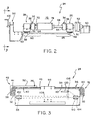
- the conveyor 24 comprises two laterally spaced, substantially complementary, or mirror image, conveyor assemblies 26, 28, each including a supporting conveyor rail 30, 32, respectively which extends lengthwise of the conveyor 26, 28 assembly.
- Each conveyor assembly 26, 28 includes a rubber drive belt 34, 36, respectively, which is generally flat on its outwardly facing side 38 and toothed on its inwardly facing side 40.
- a smooth-surfaced, low-friction, for example, nylon, bearing block 41 underlies the upper bight 43 of each belt 34, 36 to support the article 20.
- the teeth on inside 40 are for synchronization of the movement of the belts 34, 36. If the belts 34, 36 are not synchronized, articles 20 being conveyed along the conveyor 24 by the belts 34, 36 may tend to "walk" laterally one way or the other, depending upon the belt 34, 36 speed differential. This is to be avoided, particularly where the centering apparatus of Figs. 7 to 9 is not being used in conjunction with the conveyor 24.
- the belts 34, 36 are driven by toothed drive wheels 42, 44, respectively, at the upstream, inlet end 48 of the conveyor 24.
- the toothed wheels 42, 44 in turn are driven by a fluid motor 50, illustratively an air motor, on one 26 of the conveyor assemblies, through a reducing transmission 52.
- the toothed wheels 42, 44 are on separate stub shafts 54, 56, respectively, which are both splined.
- the stub shafts 54, 56 are rotatably supported on the rails 30, 32, respectively. Power is transferred from stub shaft 54 to stub shaft 56 through a large center roller 58 having a center opening 60 complementarily splined to stub shafts 54, 56.
- the large center roller 58 is generally the first point of contact of the article 20 with the conveyor 24 as the article 20 enters the inlet end 48 of the conveyor 24. Roller 58 is movable laterally of conveyor 24 on shafts 54, 56, but its movement toward drive wheel 42 is limited by a collar 62 on shaft 54.
- a toothed idler wheel 64, 66 is provided on a splined stub shaft 68, 70, respectively, at the downstream end 72 of each conveyor assembly 26, 28, respectively.
- the stub shafts 68, 70 are rotatably supported on the rails 30, 32, respectively.
- the splined shafts 68, 70 at the downstream ends 72 of the conveyor assemblies 26, 28, respectively, are coupled together by a large center roller 74 having a center opening 76 complementarily splined to stub shafts 68, 70.
- Roller 74 is movable laterally of conveyor 24 on shafts 54, 56, but its movement toward idler wheel 66 is limited by a collar 78.
- rollers 80, 82 which potentially could contact the article 20 as it passes along the conveyor 24 are driven.
- the remaining, unpowered rollers' 80, 82's primary function is to support articles 20 moving along the conveyor 24.
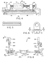
- the two complementary conveyor assemblies 26, 28 are joined by two screw threaded shafts 88, 90, each of which has a section 92 threaded in one direction and a section 94 threaded in the reverse direction.
- the screw threaded shafts 88, 90 are journalled for rotation in a side housing 96.
- the shafts 88, 90 extend through screw followers 98 at both ends of each complementary conveyor assembly 26, 28 so that rotation of the shafts 88, 90 in one direction brings the complementary conveyor assemblies 26, 28 closer together around the spindle 22 and rotation of the shafts 88, 90 in the other direction retracts the complementary conveyor assemblies 26, 28 further apart.
- Such rotation of the shafts 88, 90 can be effected either automatically, for example, by a computer-controlled electric motor, or manually.
- rotation of the shafts 88, 90 is effected manually by a hand crank 100 journalled for rotation in side housing 96.
- a sprocket 102, 104 is provided adjacent the end of each shaft 88, 90, respectively, where it is journalled for rotation in the housing 96, and a roller chain 106 is trained about these two sprockets 102, 104 and a sprocket 108 on the hand crank 100.
- the shafts 88, 90 are rotated synchronously to insure equal spacing of the complementary conveyor assemblies 26, 28 at the entry 48 and exit 72 ends of the conveyor 24.
- the conveyor 24 is supported on an elevator 110. Once an article 20 has come to a stop or nearly to a stop on the conveyor 24, for example, in the capture range of the spindle 22, the article 20 must be permitted to move freely in that limited range both in the upstream-downstream and lateral directions. Otherwise capture of the article 20 by the spindle 22, for example, as the elevator 110 lowers the conveyor 24 with respect to the spindle 22, may be rendered difficult or impossible. If this happens, damage to the spindle 22 or the conveyor 24 or both may result. Freedom of movement of articles 20 upstream or downstream in the capture region is enhanced by the choice of a fluid motor 50 characterized by easy back-driving, that is one which is not resistant to being rotated in a reverse direction when it is not being driven in a forward direction. An example is the Pneumatic Systems, Inc. Model DVAR-Y air motor.
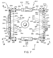
- a centering mechanism 200 constructed according to the invention includes two assemblies 202, 204 and two double-acting, fluid, illustratively, pneumatic piston-and-cylinder, motors 206, 208, all of which bolt or otherwise attach to an imbalance determining machine elevator 110.
- the assemblies 202, 204 attach to the longitudinally extending sides of the elevator 110 and the air motors 206, 208 attach to the transversely extending ends of the elevator 110.
- Each assembly 202, 204 includes a supporting frame 210, 212, respectively, and two upwardly projecting posts 214, 216 which are pivotally mounted at their vertically lower ends 218 in the frame 210, 212.
- a sprocket 220, 222 is mounted on the lower end 218 of each post 214, 216, respectively, generally within the frame 210, 212. Additional idler sprockets 226, 228 are rotatably mounted at the upstream 230 and downstream 232 ends of the frame 210, 212, respectively.
- the posts 214, 216 are joined adjacent their upper ends 234, 236, respectively, by a bracket 238.
- the posts 214, 216 extend rotatably through the bracket 238.
- the bracket 238 adds some rigidity to the assembly 202, 204.
- a centering arm 240 is fixed to the vertically upper end 234, 236 of each post 214, 216.
- the centering arm 240 is provided at its distal end 242 with a contact pin 244. Additional rollers 246 are rotatably mounted between the proximal 214, 216 and distal 242 ends of the arm 240 to provide relatively lower friction contact with an article 20 to be centered by the centering mechanism
- a length 250 of roller chain is attached at one end to one end of the piston rod 254 of the upstream air motor 206, is trained about the idler sprocket 226 at the upstream end 230 of the assembly 204, the outside (side away from the spindle 22) of the upstream sprocket 220, the inside (side toward the spindle 22) of the downstream sprocket 222, and the idler sprocket 228 at the downstream end 232 of the assembly 204, and is attached at its other end to one end of the piston rod 256 of the downstream air motor 208.
- a length 258 of roller chain is attached at one end to the other end of the piston rod 254 of the upstream air motor 206, is trained about the idler sprocket 226 at the upstream end 230 of the assembly 202, the inside of the upstream sprocket 220, the outside of the downstream sprocket 222, and the idler sprocket 228 at the downstream end of the assembly, and is attached at its other end to the other end of the piston rod 258 of the downstream air motor 208.
Landscapes
- Engineering & Computer Science (AREA)
- Mechanical Engineering (AREA)
- Rollers For Roller Conveyors For Transfer (AREA)
- Attitude Control For Articles On Conveyors (AREA)
- Intermediate Stations On Conveyors (AREA)
- Structure Of Belt Conveyors (AREA)
- Framework For Endless Conveyors (AREA)
- Control Of Conveyors (AREA)
Priority Applications (1)
| Application Number | Priority Date | Filing Date | Title |
|---|---|---|---|
| EP97203080A EP0819624B1 (fr) | 1994-10-11 | 1995-10-10 | Dispositif de centrage |
Applications Claiming Priority (2)
| Application Number | Priority Date | Filing Date | Title |
|---|---|---|---|
| US320905 | 1994-10-11 | ||
| US08/320,905 US5566816A (en) | 1994-10-11 | 1994-10-11 | Conveying and centering apparatus |
Related Child Applications (1)
| Application Number | Title | Priority Date | Filing Date |
|---|---|---|---|
| EP97203080A Division EP0819624B1 (fr) | 1994-10-11 | 1995-10-10 | Dispositif de centrage |
Publications (3)
| Publication Number | Publication Date |
|---|---|
| EP0706959A2 true EP0706959A2 (fr) | 1996-04-17 |
| EP0706959A3 EP0706959A3 (fr) | 1996-08-14 |
| EP0706959B1 EP0706959B1 (fr) | 1999-09-01 |
Family
ID=23248345
Family Applications (2)
| Application Number | Title | Priority Date | Filing Date |
|---|---|---|---|
| EP97203080A Expired - Lifetime EP0819624B1 (fr) | 1994-10-11 | 1995-10-10 | Dispositif de centrage |
| EP95307151A Expired - Lifetime EP0706959B1 (fr) | 1994-10-11 | 1995-10-10 | Appareil de transport |
Family Applications Before (1)
| Application Number | Title | Priority Date | Filing Date |
|---|---|---|---|
| EP97203080A Expired - Lifetime EP0819624B1 (fr) | 1994-10-11 | 1995-10-10 | Dispositif de centrage |
Country Status (5)
| Country | Link |
|---|---|
| US (2) | US5566816A (fr) |
| EP (2) | EP0819624B1 (fr) |
| JP (1) | JPH08175640A (fr) |
| CA (1) | CA2159057C (fr) |
| DE (2) | DE69514689T2 (fr) |
Cited By (2)
| Publication number | Priority date | Publication date | Assignee | Title |
|---|---|---|---|---|
| ITFI20130099A1 (it) * | 2013-05-03 | 2014-11-04 | Makor S R L Unipersonale | Apparato per il trattamento di semilavorati |
| CN106081475A (zh) * | 2016-08-22 | 2016-11-09 | 无锡先导智能装备股份有限公司 | 一种间距可调的皮带输送装置 |
Families Citing this family (33)
| Publication number | Priority date | Publication date | Assignee | Title |
|---|---|---|---|---|
| US6372530B1 (en) * | 1995-11-06 | 2002-04-16 | Micron Technology, Inc. | Method of manufacturing a cold-cathode emitter transistor device |
| JP3392618B2 (ja) * | 1996-02-21 | 2003-03-31 | 三菱重工業株式会社 | ベルト供給装置のセンタリング方法及び装置 |
| US6069342A (en) * | 1996-12-18 | 2000-05-30 | Texas Instruments Incorporated | Automated multiple lead frame strip radiant die attach material curing apparatus |
| US6082191A (en) * | 1997-01-24 | 2000-07-04 | Illinois Tool Works, Inc. | Inlet conveyor for tire testing systems |
| US6016695A (en) * | 1997-01-24 | 2000-01-25 | Illinois Tool Works Inc. | Tire uniformity testing system |
| US5992227A (en) * | 1997-01-24 | 1999-11-30 | Jellison; Frank R. | Automatic adjustable width chuck apparatus for tire testing systems |
| US5979231A (en) * | 1997-01-24 | 1999-11-09 | Illinois Tool Works, Inc. | Loadwheel assembly for tire testing systems having conical support plates |
| US5944477A (en) * | 1997-05-27 | 1999-08-31 | Systematic Machinery Llc | Bundle squaring machine |
| US6032788A (en) * | 1998-02-26 | 2000-03-07 | Dek Printing Machines Limited | Multi-rail board transport system |
| DE10059312C2 (de) * | 2000-11-29 | 2002-10-24 | Strothmann Gmbh & Co Kg Maschb | Zentriervorrichtung für Fördergut |
| ITMI20030622A1 (it) * | 2003-03-28 | 2004-09-29 | Univer Spa | Dispositivo di centraggio con mezzi di pulizia |
| US7210572B2 (en) * | 2005-02-03 | 2007-05-01 | Advanced Manufacturing Technology | Adjustable guide for a bottle handling system |
| US20070095247A1 (en) * | 2005-02-03 | 2007-05-03 | Advanced Manufacturing Technology | Guide positioning system for a container transport line |
| DE102006035648A1 (de) * | 2006-07-31 | 2008-02-07 | Kaindl Flooring Gmbh | Vorrichtung zum Herstellen oder/und Bearbeiten von Paneelen |
| DE102008023762A1 (de) * | 2007-09-13 | 2009-03-19 | Multivac Sepp Haggenmüller Gmbh & Co. Kg | Vorrichtung zur Aufnahme und zum Transport eines Gutes |
| US9725246B2 (en) | 2008-05-20 | 2017-08-08 | Flexibility Engineering, Llc | Flow restricted positioner control apparatus and methods |
| US9133865B2 (en) | 2008-05-20 | 2015-09-15 | Flexibility Engineering, Llc | Position control apparatus |
| EP2367744A2 (fr) * | 2008-11-06 | 2011-09-28 | Ima-Pg India Limited | Système ajustable pour transfert et accumulation de dispositifs pharmaceutiques |
| US8347920B2 (en) * | 2010-01-29 | 2013-01-08 | Flexibility Engineering, Llc | Pressurized fluid positioner control system |
| CN101844632B (zh) * | 2010-06-11 | 2011-09-21 | 山东新华医疗器械股份有限公司 | 快速步进式传送设备 |
| US20120037478A1 (en) * | 2010-08-11 | 2012-02-16 | Du Pont Apollo Limited | Roller convey system |
| JP5784347B2 (ja) * | 2011-04-07 | 2015-09-24 | 株式会社神戸製鋼所 | タイヤ試験機用コンベア |
| CN102849444B (zh) * | 2011-06-29 | 2014-10-29 | 深南电路有限公司 | 对中定位装置 |
| US9677576B2 (en) | 2015-09-14 | 2017-06-13 | Flexbility Engineering, LLC | Flow restricted positioner control apparatus and methods |
| US10314226B2 (en) * | 2016-06-29 | 2019-06-11 | Agco Corporation | Shaft for side-by-side conveyor |
| CN108555794A (zh) * | 2018-03-01 | 2018-09-21 | 严加伟 | 一种对中定位装置 |
| CN110436158B (zh) * | 2019-09-11 | 2024-07-02 | 惠州市源丰达自动化设备有限公司 | 一种转角机 |
| CN110921256A (zh) * | 2019-10-22 | 2020-03-27 | 浙江省建工集团有限责任公司 | 一种钢板导向装置 |
| CN112811088A (zh) * | 2021-01-04 | 2021-05-18 | 广东长虹电子有限公司 | 一种输送机构 |
| CN113928780A (zh) * | 2021-10-21 | 2022-01-14 | 洛阳富道生物科技有限公司 | 一种顶板层送料机构 |
| WO2025122567A1 (fr) * | 2023-12-07 | 2025-06-12 | Curt G. Joa, Inc. | Systèmes et procédés de correction d'obliquité dans des composants manufacturés |
| EP4729444A1 (fr) * | 2024-10-18 | 2026-04-22 | Moovimenta AG | Convoyeur de palettes comprenant une première et une seconde bande transporteuse et une pluralité de rouleaux de convoyeur |
| KR102913528B1 (ko) * | 2025-03-12 | 2026-01-19 | 주식회사 비에이치에스티 | 폭 가변형 벨트 컨베이어 |
Family Cites Families (19)
| Publication number | Priority date | Publication date | Assignee | Title |
|---|---|---|---|---|
| US3089576A (en) * | 1960-12-16 | 1963-05-14 | Signode Steel Strapping Co | Locating device |
| US3225890A (en) * | 1963-11-29 | 1965-12-28 | Kaiser Steel Corp | Article aligning apparatus |
| US3965523A (en) * | 1974-09-16 | 1976-06-29 | J. P. Elliott Associates, Inc. | Bearing washer |
| US4191055A (en) * | 1978-07-25 | 1980-03-04 | Ransburg Corporation | Dynamic imbalance determining system |
| JPS5623112A (en) * | 1979-07-31 | 1981-03-04 | Natl House Ind Co Ltd | Locating device |
| US4381108A (en) * | 1981-06-29 | 1983-04-26 | Newsome John R | Device for aligning signatures fed in shingled relation |
| JPS59143806A (ja) * | 1983-02-08 | 1984-08-17 | Sanshin Shokai:Kk | フリ−フロ−コンベヤのパレツト走行路平行出し機構 |
| DE3406719A1 (de) * | 1984-02-24 | 1985-08-29 | Collmann GmbH & Co, Spezialmaschinenbau KG, 2400 Lübeck | Vorrichtung zum positionieren von reifen |
| JPS61226415A (ja) * | 1985-03-29 | 1986-10-08 | Ngk Insulators Ltd | 搬送物の位置調節装置 |
| DE8535683U1 (de) * | 1985-12-19 | 1986-02-27 | Carl Schenck Ag, 6100 Darmstadt | Fördereinrichtung mit angetriebenen, armierten Gurten zum Transport von beladenen Paletten |
| US4754867A (en) * | 1986-09-19 | 1988-07-05 | Zenith Electronics Corporation | Automated belt drive for PC board feed apparatus |
| US4780040A (en) * | 1987-12-11 | 1988-10-25 | Research, Incorporated | Conveyor guide arrangement |
| JP2774844B2 (ja) * | 1989-11-30 | 1998-07-09 | 昭和アルミニウム株式会社 | パイプのセンタリング装置 |
| DE4036510A1 (de) * | 1990-11-16 | 1992-05-21 | Bosch Gmbh Robert | Foerdereinrichtung in verpackungsmaschinen |
| US5101959A (en) * | 1991-01-14 | 1992-04-07 | Premark Feg Corporation | Aligning device for conveyed articles |
| ES2101075T3 (es) * | 1991-11-13 | 1997-07-01 | Ciba Geigy Ag | Dispositivo de recubrimiento para placas. |
| US5240104A (en) * | 1992-01-31 | 1993-08-31 | Douglas John J | Printed circuit board belt conveyor |
| US5354571A (en) * | 1992-04-27 | 1994-10-11 | Rheon Automatic Machinery Co., Ltd. | Method for aligning and bending individual round elongated dough pieces |
| AT404687B (de) * | 1993-05-04 | 1999-01-25 | Sticht Fertigungstech Stiwa | Anlage zur bearbeitung und/oder montage von bauteilen |
-
1994
- 1994-10-11 US US08/320,905 patent/US5566816A/en not_active Expired - Lifetime
-
1995
- 1995-09-25 CA CA002159057A patent/CA2159057C/fr not_active Expired - Lifetime
- 1995-10-09 JP JP7261429A patent/JPH08175640A/ja active Pending
- 1995-10-10 DE DE69514689T patent/DE69514689T2/de not_active Expired - Fee Related
- 1995-10-10 DE DE69511811T patent/DE69511811T2/de not_active Expired - Fee Related
- 1995-10-10 EP EP97203080A patent/EP0819624B1/fr not_active Expired - Lifetime
- 1995-10-10 EP EP95307151A patent/EP0706959B1/fr not_active Expired - Lifetime
-
1996
- 1996-03-21 US US08/619,996 patent/US5605215A/en not_active Expired - Lifetime
Cited By (2)
| Publication number | Priority date | Publication date | Assignee | Title |
|---|---|---|---|---|
| ITFI20130099A1 (it) * | 2013-05-03 | 2014-11-04 | Makor S R L Unipersonale | Apparato per il trattamento di semilavorati |
| CN106081475A (zh) * | 2016-08-22 | 2016-11-09 | 无锡先导智能装备股份有限公司 | 一种间距可调的皮带输送装置 |
Also Published As
| Publication number | Publication date |
|---|---|
| US5605215A (en) | 1997-02-25 |
| CA2159057C (fr) | 2001-12-25 |
| EP0706959A3 (fr) | 1996-08-14 |
| DE69514689T2 (de) | 2000-08-31 |
| DE69511811T2 (de) | 1999-12-23 |
| EP0819624B1 (fr) | 2000-01-19 |
| DE69514689D1 (de) | 2000-02-24 |
| CA2159057A1 (fr) | 1996-04-12 |
| US5566816A (en) | 1996-10-22 |
| EP0706959B1 (fr) | 1999-09-01 |
| JPH08175640A (ja) | 1996-07-09 |
| EP0819624A1 (fr) | 1998-01-21 |
| DE69511811D1 (de) | 1999-10-07 |
Similar Documents
| Publication | Publication Date | Title |
|---|---|---|
| EP0706959B1 (fr) | Appareil de transport | |
| US4730718A (en) | Bi-directional transfer mechanism | |
| US7040478B2 (en) | Steerable diverter system | |
| US7806254B2 (en) | Belt conveyor and method | |
| CA2482069C (fr) | Transporteur a courroie incurve | |
| US4887708A (en) | Drive apparatus for belt power turns | |
| US4792034A (en) | Twisted flat belt drive for line shaft conveyors | |
| US5407061A (en) | Slat conveyor | |
| EP1556295B1 (fr) | Unité de convoyage ayant un accouplement servant à régler la position angulaire relative de deux parties de convoyeur contiguës | |
| CA2532225A1 (fr) | Accumulateur a transmission a courroie pour segment de rouleaux courbe | |
| CA2344996C (fr) | Convoyeur mecanique en deux sections et dispositif de centrage | |
| EP1008522B1 (fr) | Dispositif d'enveloppement | |
| HUT74651A (en) | Drive system for curved escalator | |
| GB2102369A (en) | Discharging goods from rollerways | |
| JPH07117837A (ja) | 転倒し易い容器等の中間抱き込み搬送機 | |
| JP4031850B2 (ja) | 枚葉材料処理装置 | |
| EP1818293A1 (fr) | Transporteur | |
| JP3238131B2 (ja) | ローラコンベア | |
| JPH08104411A (ja) | スラットコンベヤにおけるチェーン支持装置 | |
| ATE134967T1 (de) | Förderer | |
| US4987994A (en) | Spur conveyor assembly | |
| GB2074968A (en) | Improvements in or relating to a flexible conveyor belt supporting structure | |
| JP4085841B2 (ja) | コンベヤ設備 | |
| JPH0432331Y2 (fr) | ||
| JPH06115654A (ja) | 搬送装置 |
Legal Events
| Date | Code | Title | Description |
|---|---|---|---|
| PUAI | Public reference made under article 153(3) epc to a published international application that has entered the european phase |
Free format text: ORIGINAL CODE: 0009012 |
|
| AK | Designated contracting states |
Kind code of ref document: A2 Designated state(s): DE FR GB IT |
|
| PUAL | Search report despatched |
Free format text: ORIGINAL CODE: 0009013 |
|
| AK | Designated contracting states |
Kind code of ref document: A3 Designated state(s): DE FR GB IT |
|
| 17P | Request for examination filed |
Effective date: 19970207 |
|
| 17Q | First examination report despatched |
Effective date: 19970804 |
|
| GRAG | Despatch of communication of intention to grant |
Free format text: ORIGINAL CODE: EPIDOS AGRA |
|
| GRAG | Despatch of communication of intention to grant |
Free format text: ORIGINAL CODE: EPIDOS AGRA |
|
| GRAH | Despatch of communication of intention to grant a patent |
Free format text: ORIGINAL CODE: EPIDOS IGRA |
|
| GRAH | Despatch of communication of intention to grant a patent |
Free format text: ORIGINAL CODE: EPIDOS IGRA |
|
| GRAA | (expected) grant |
Free format text: ORIGINAL CODE: 0009210 |
|
| AK | Designated contracting states |
Kind code of ref document: B1 Designated state(s): DE FR GB IT |
|
| REF | Corresponds to: |
Ref document number: 69511811 Country of ref document: DE Date of ref document: 19991007 |
|
| ITF | It: translation for a ep patent filed | ||
| ET | Fr: translation filed | ||
| PLBE | No opposition filed within time limit |
Free format text: ORIGINAL CODE: 0009261 |
|
| STAA | Information on the status of an ep patent application or granted ep patent |
Free format text: STATUS: NO OPPOSITION FILED WITHIN TIME LIMIT |
|
| 26N | No opposition filed | ||
| REG | Reference to a national code |
Ref country code: GB Ref legal event code: IF02 |
|
| PGFP | Annual fee paid to national office [announced via postgrant information from national office to epo] |
Ref country code: GB Payment date: 20051005 Year of fee payment: 11 |
|
| PGFP | Annual fee paid to national office [announced via postgrant information from national office to epo] |
Ref country code: FR Payment date: 20051017 Year of fee payment: 11 |
|
| PGFP | Annual fee paid to national office [announced via postgrant information from national office to epo] |
Ref country code: DE Payment date: 20051130 Year of fee payment: 11 |
|
| PG25 | Lapsed in a contracting state [announced via postgrant information from national office to epo] |
Ref country code: DE Free format text: LAPSE BECAUSE OF NON-PAYMENT OF DUE FEES Effective date: 20070501 |
|
| GBPC | Gb: european patent ceased through non-payment of renewal fee |
Effective date: 20061010 |
|
| REG | Reference to a national code |
Ref country code: FR Ref legal event code: ST Effective date: 20070629 |
|
| PG25 | Lapsed in a contracting state [announced via postgrant information from national office to epo] |
Ref country code: GB Free format text: LAPSE BECAUSE OF NON-PAYMENT OF DUE FEES Effective date: 20061010 |
|
| PG25 | Lapsed in a contracting state [announced via postgrant information from national office to epo] |
Ref country code: FR Free format text: LAPSE BECAUSE OF NON-PAYMENT OF DUE FEES Effective date: 20061031 |
|
| PGFP | Annual fee paid to national office [announced via postgrant information from national office to epo] |
Ref country code: IT Payment date: 20141028 Year of fee payment: 20 |