EP0707101A2 - Device for feeding weft threads into the shed in air looms - Google Patents
Device for feeding weft threads into the shed in air looms Download PDFInfo
- Publication number
- EP0707101A2 EP0707101A2 EP95115223A EP95115223A EP0707101A2 EP 0707101 A2 EP0707101 A2 EP 0707101A2 EP 95115223 A EP95115223 A EP 95115223A EP 95115223 A EP95115223 A EP 95115223A EP 0707101 A2 EP0707101 A2 EP 0707101A2
- Authority
- EP
- European Patent Office
- Prior art keywords
- air
- air duct
- shed
- weft
- angle
- Prior art date
- Legal status (The legal status is an assumption and is not a legal conclusion. Google has not performed a legal analysis and makes no representation as to the accuracy of the status listed.)
- Withdrawn
Links
Images


Classifications
-
- D—TEXTILES; PAPER
- D03—WEAVING
- D03D—WOVEN FABRICS; METHODS OF WEAVING; LOOMS
- D03D47/00—Looms in which bulk supply of weft does not pass through shed, e.g. shuttleless looms, gripper shuttle looms, dummy shuttle looms
- D03D47/28—Looms in which bulk supply of weft does not pass through shed, e.g. shuttleless looms, gripper shuttle looms, dummy shuttle looms wherein the weft itself is projected into the shed
- D03D47/30—Looms in which bulk supply of weft does not pass through shed, e.g. shuttleless looms, gripper shuttle looms, dummy shuttle looms wherein the weft itself is projected into the shed by gas jet
- D03D47/3066—Control or handling of the weft at or after arrival
- D03D47/308—Stretching or holding the weft
-
- D—TEXTILES; PAPER
- D03—WEAVING
- D03D—WOVEN FABRICS; METHODS OF WEAVING; LOOMS
- D03D47/00—Looms in which bulk supply of weft does not pass through shed, e.g. shuttleless looms, gripper shuttle looms, dummy shuttle looms
- D03D47/28—Looms in which bulk supply of weft does not pass through shed, e.g. shuttleless looms, gripper shuttle looms, dummy shuttle looms wherein the weft itself is projected into the shed
- D03D47/30—Looms in which bulk supply of weft does not pass through shed, e.g. shuttleless looms, gripper shuttle looms, dummy shuttle looms wherein the weft itself is projected into the shed by gas jet
- D03D47/3006—Construction of the nozzles
- D03D47/302—Auxiliary nozzles
Definitions
- the invention relates to a device for inserting the weft thread into the shed of an air jet loom connected to a compressed air source, with a sley that can be moved back and forth transversely to the insertion direction of the weft thread, a reed provided on the fabric side with a first air channel and a number spaced apart from one another arranged on the sley and depending on the movement in the shed and again extractable and in connection with the compressed air source connected to the nozzle body, wherein in the first air duct from the individual nozzle bodies, each provided with an outlet opening, pressurized with compressed air transported through the shed through means arranged on the outlet side is held.
- Air jet weaving machines in which the weft thread is inserted or shot into the shed by means of a compressed air jet emitted by a high-pressure nozzle and when inserted by means of a plurality of spaced apart ones in the entry direction and immersed in the shed and extractable nozzle body is additionally acted upon by compressed air are generally known.
- the individual nozzle bodies require a relatively large amount of air due to their design and the arrangement of the outlet opening, and especially when immersed in the shed, they are often deformed by the relatively closely spaced warp threads in such a way that after a relatively short operating time the Damaged nozzle body to avoid damage to the warp threads, etc. must be replaced by a relatively time-consuming and costly assembly.
- Another disadvantage is that the weft thread end must be dimensioned relatively long so that it can be gripped and held securely up to the fabric-side stop, the weft thread end being cut off on the outlet side in a manner known per se.
- the invention has for its object to improve a device of the generic type in such a way that, due to an advantageous configuration of the individual nozzle bodies, trouble-free immersion and removal of the same and sufficient pressurized air pressure on the weft thread over the entire shed width is ensured, and due to further means an exact hold of the exit-side weft end is reached until the weft thread stops on the fabric side.
- the individual nozzle body be provided with a nozzle part which is elliptical in profile cross section and closed by a head part assigned to the shed in the form of a tip and which has at least one outlet opening on one wall part facing the first air duct, the outlet opening with respect to its central axis on the one hand at a first angle oriented obliquely upwards in the direction of the first air duct and on the other hand at an in
- the weft direction is arranged in the plane of the laterally oriented second angle in the wall part of the nozzle part, and that on the outlet side a guide member corresponding to the first air duct is provided, which has a second air duct corresponding to the first air duct, in which the weft thread end is acted upon by an additional compressed air jet until tissue-side stop is held in an extended position.
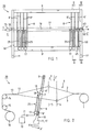
- FIG. 1 shows a schematic and in view view of a sley 10 for an air jet weaving machine, designated as a whole with 20, with the essential functional elements for the pneumatic entry, transport and holding of the weft thread 18 to be inserted into a shed 12 (FIG. 2/3).
- loom 20 For simplification the air jet loom will be referred to as loom 20 hereinafter.
- the sley 10 essentially comprises two vertical side bars 11 and 11 'arranged at a distance from one another, two transverse bars arranged thereon in a vertical direction at a distance from one another and fastened in a manner not shown 9 and 9 'as well as reeds 8' arranged at a distance from each other, which are fastened to the cross bars 9, 9 'in a manner not shown.
- the reeds 8 'each provided with a recess 7 (FIG. 2) together form a weaving comb or reed 8 oriented over the entire width of the sley 10.
- the recesses 7 on the individual reeds 8' together form one shown schematically in FIG Guide channel 19 for the weft thread 18.
- the reed 8 which extends over the entire width of the sley 10, is only partially shown in the two outer regions of the sley 10.
- FIG. 1 a high-pressure nozzle 75, assigned and schematically shown in the area of the entry side E of the sley 10, for the air jet (not shown) oriented in the direction of the arrow Y for the insertion of the weft thread 18 into the shed 12 (FIG. 2).
- the device 50 provided with a guide member 60 for holding the weft end 18 'emerging laterally in the direction of the arrow Y' is arranged in the region of the sley 10 on the opposite discharge side E '.
- the device 50 arranged on the sley 10 in the region of the discharge side E ' is fastened to the lower cross member 9' in a manner not shown with a supporting part 65.
- the reeds 8 'of the reed 8, which are arranged at a distance from one another, are assigned individual nozzle elements 25.
- the nozzle elements 25 arranged over the entire width of the sley 10 are each exchangeably fastened to the lower cross member 9 'by means not shown.
- the nozzle elements 25 arranged in series are each provided with one or more outlet openings (not shown) at the upper end.
- the outlet openings are designed and in each case arranged at the upper end of the nozzle body 25 in such a way that the weft thread 18 shot into the guide channel 19 of the reed 8 passes over the entire width of the sley 10, that is, from the entry side E to the discharge side E 'can also be acted upon with compressed air.
- the nozzle bodies 25 arranged in a row, as shown schematically in FIG. 2, are connected to an associated compressed air source 70 via a line 71 connected to a holding piece 17 in a manner not shown.
- the nozzle body 25 which is arranged at a distance from one another over the entire width of the sley 10, the weft thread 18 is transported through the guide channel 19 in an exactly stretched position.
- FIG. 2 shows the weaving machine 20 as a schematic diagram and the essential functional elements for the formation of the shed 12 can be seen.
- warp threads 2 and 3 drawn off from a schematically illustrated storage device 1 are used to form the shed 12 in a manner known per se by correspondingly arranged and designed heald frames 4 and 5 alternately raised or lowered in the direction of the arrow Z or Z '.
- the heald frames 4 and 5 are provided with separate healds (not shown) for the separate passage of the individual warp threads 2 and 3, the heald frames 4 and 5 as well as the healds together forming a weaving harness designated as a whole by 6.
- the sley 10 which can be moved back and forth in the direction of the arrows X and X '(not shown).
- the sley 10 formed as a frame comprises the side rails 11 and 11' (FIG. 1) arranged at a distance from one another and the two attached to it and the two side rails 11 and 11 'connecting cross bars 9 and 9'.
- the weft thread 18 is drawn off in a manner known per se from a supply spool (not shown) and inserted (shot in) into the guide channel 19 by means of the high-pressure nozzle 75 (FIG. 1) arranged on the side of the sley 10.
- the weft thread 18 inserted in the guide channel 19 is additionally supplied with compressed air through the shed 12 by means of the nozzle elements 25 arranged in series and struck by the reed 8 moved in the direction of the arrow X against a fabric 13 shown schematically in FIG. In this phase, the weft thread 18 is woven into the fabric 13.
- the individual nozzle elements 25 are arranged on the lower cross member 9 'of the sley 10 and fastened with means (not shown) such that they dip into the shed 12 when the sley 19 moves in the direction of the arrow X.
- the special design of the individual nozzle element 25 will be described in detail later in connection with FIGS. 4 to 8.
- the sley 10 with the reed 8 is moved in the direction of the arrow X ', so that the individual nozzle elements 25 (FIG. 2) arranged in series on the cross member 9' are pulled out of the shed 12 again become.
- a so-called shed change of the individual warp threads 2 and 3 is carried out for the formation of a next shed 12 for the next entry of the weft thread 18 by actuating the heald frames 4 and 5 in the direction of arrows Z and Z '.
- the individual nozzle bodies 25, as shown schematically in FIGS. 1 and 2 are each arranged interchangeably in the holding piece 17.
- the holding pieces connected via a line 71 to a compressed air source 70, which is shown schematically in FIG 17 for the nozzle elements 25 are preferably exchangeably attached to the lower cross member 9 'of the sley 10.
- the movements of the heald frames 4 and 5 oriented in the direction of the arrows Z and Z 'and the movements of the sley 10 with the reed 8 oriented in the direction of the arrows X and X' are carried out in a manner known per se by means of drive means (not shown).
- the fabric 13 formed by the individual functions described above is, for example, as shown schematically in FIG. 2 and FIG. 3, passed over a first and a second goods take-off tree 14 and 15 and wound onto a goods tree 16 rotatably driven about its longitudinal axis.
- the goods take-off trees 14, 15, which are operatively connected to drive means (not shown), and the goods tree 16 provided for receiving the fabric 13 are not the subject of this invention and are therefore shown only schematically.
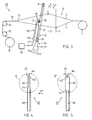
- FIG. 3 shows the weaving machine 20 along the line III-III in FIG. 1 as a further schematic diagram and one recognizes the functional elements 1 to 10 and 65 and 70 and 70 etc. described above in connection with FIG. 2 for the shed and Tissue formation.
- FIG. 3 shows the device 50 which is fastened to the sley 10 on the outlet side (FIG. 1) by means of a supporting part 65 and by means of which the weft thread end 18 '(FIG. 1) is held in an extended position.
- a line 71 ' which is connected to the schematically illustrated compressed air source 70, is connected to the support part 65 of the device 50.
- the device 50 for holding the weft thread end 18 ' is described in more detail below in connection with FIGS. 9 to 11.
- the nozzle body 25 comprises a first section 30, a second section 35 formed thereon and an integrally formed thereon third section 40, the third section 40 hereinafter being referred to as nozzle part 40.
- the second section 35 which tapers conically by mechanical deformation (pressing together) in the direction of the nozzle part 40, is formed on the first cylindrical section 30.
- the nozzle part 40 which is compressed approximately in an ellipse (FIG. 8), adjoins the second section 35.
- the nozzle part 40 is closed by an integrally formed head part 45, which is designed approximately as a projectile-shaped tapered tip 46.
- At least one outlet opening 43 is provided on the side of the head part 45 of the nozzle body 25.
- the nozzle body 25 is shown in a view according to the arrow direction K ′′ drawn in FIG. 2 and the cylindrical first section 30 can be seen, the second section 35 which widens conically in the direction of the nozzle part 40 in this view, as well as that in the latter View due to the mechanical deformation larger than the first cylindrical section 30 formed nozzle part 40.
- the outlet opening 43 is provided in the upper region of the nozzle part 40, which is in communication with the interior 25 '(FIG. 6) of the nozzle body 25.
- the special design of the individual sections 30, 35, 40 and 45 of the nozzle body 25, as well as the arrangement of the outlet opening 43 provided in the nozzle part 40 and the special design of the head part 45 are described in detail below in connection with FIGS. 6 to 8.
- FIG. 6 shows a section of the nozzle body 25, shown partially in section, on a larger scale and in FIG. 4 by a circle K, and the first cylindrical section 30 provided with a first passage channel 29 can be seen, which has a conically tapering in this view second passage 35 provided second section 35 and the nozzle part 40 provided with a third passage 39.
- the nozzle part 40 is at its upper End closed by the integrally formed and essentially hood-shaped head part 45.
- the channels 29, 34 and 39 which are oriented in the axial direction of the nozzle body 25 and at one end delimited by the head part 45, are connected to one another and together form the interior 25 'of the nozzle body 25.
- the nozzle part 40 which is largely elliptical in profile, has a first one arcuate side wall 41 (FIG. 8) and a second arcuate side wall 42 (FIG. 8) formed thereon, the two side walls 41, 42 being connected to one another in the outer region by a bend 47 and 47 '(FIG. 8).
- At least one outlet opening 43 which is connected to the passage channels 29, 34 and 39 of the sections 30, 35 and 40, is arranged in the second side wall 42.
- the outlet opening 43 arranged centrally on an imaginary central axis M is arranged at a distance C from the tip 46 of the head piece 45.
- the distance C is selected such that a chamber 44 is formed between the inside 45 'of the head piece 45 and the inside surface 43' of the, for example, circular outlet opening 43.
- the chamber 44 which is designed approximately as a semicircular ring and, as shown schematically in FIG. 7, surrounds the outlet opening 43, essentially serves to deflect the air jet (not shown) directed into the interior 25 'of the nozzle body 25 and against the inside 45' of the head piece 45.
- the outlet opening 43 arranged in the second side wall 42 of the head part 45 is, as shown in FIG imaginary center axis M directed obliquely upwards at a first angle ⁇ in the direction of the tip 46 of the head part 45 and, on the other hand, as shown in the plan view according to FIG. 8, with respect to the imaginary axis of symmetry S of the nozzle body 25 arranged in the plane in the direction of the weft thread 18 at a second angle ⁇ 'in the second side wall 42.
- the outlet opening 43 has a diameter of 1.5 mm, for example.
- the first angle ⁇ of the outlet opening 43 oriented obliquely upwards with respect to the imaginary central axis M is approximately in the order of 8 ° to 15 °.
- the length B, oriented in the axial direction, of the nozzle part 40 which is elliptical in profile cross section (FIG. 8), is approximately 5 times the length A, oriented in the axial direction, of the central, conically tapering second section 35
- the length A is approximately 3 mm and the length B is approximately 15 mm.
- the length C extending from the imaginary central axis M of the outlet opening 43 to the head part 45 is, for example, 2 mm.
- the individual nozzle body 25 is preferably made of a stainless steel, which is preferably relatively easy to deform.
- the outer circumferential surface of the elliptically shaped nozzle part 40, but preferably the entire nozzle body 25, is completely ground after the individual shaping and processing operations, so that the outer shape of the nozzle body has an absolutely smooth surface.
- the second side wall 42 it is also possible to arrange a plurality of outlet openings 43 which are arranged in mutually distributed formations and which penetrate the second side wall 42.
- the individual outlet openings 43 are corresponding to the above described and arranged in relation to the imaginary central axis M (FIG. 6) and to the axis of symmetry S (FIG. 8) in the second side wall 42.
- the diameter of the respective outlet opening 43 is preferably on the order of 1.0 mm to 2.0 mm. If several outlet openings are arranged, they are correspondingly smaller in diameter.
- the two side walls 41 and 42 of the nozzle part 40 are each provided with a wall part 41 ′ and 42 ′ that is inclined in the direction of the tip 46 of the head part 45.
- One wall part 41 ' is with respect to the first vertical side wall 41 at a first angle of inclination ⁇ in the order of about 15 ° to 25 ° and the other wall part 42' is with respect to the second vertical side wall 42 of the nozzle body 40 under a second Inclination angle ⁇ 'in the order of magnitude of approximately 40 ° to 50 ° is inclined in the direction of the tip 46 of the head part 45.
- the first angle of inclination ⁇ is approximately 22 ° and the second angle of inclination ⁇ 'is approximately 48 °.
- FIG. 7 shows the section of the nozzle body 25 designated by a circle K 'in FIG. 5 and shown partially in section, and the first cylindrical section 30 can be seen, which in this view is conically expanded due to the deformation in relation to the first section 30 Section 35 and the nozzle part 40 with the head part 45. Furthermore, one can see the outlet opening 43 arranged in the first side wall 42 (FIG. 6) and the chamber 44 formed above it essentially as a semicircular ring.
- FIG. 8 shows the nozzle body 25 according to the line VIII-VIII shown in FIG. 6 in top view and in section, and one can see the two sections 30 and 35 and the nozzle part 40 with the elliptical side walls 41 and 42 and bends 47 and 47 '.
- the outlet opening 43 which is oriented essentially in the insertion direction of the weft thread 18 (FIG. 1), is arranged in the side wall 42.
- FIG. 9 shows the device 50 shown in view and partly in section and designed to hold the inserted weft end, which essentially comprises the supporting part 65, an inlet air line 55 arranged thereon and formed from a tubular body, and a holding and guide member 60 arranged thereon.
- the individual elements of the device 50 are described below, the holding and guide member 60 being referred to as a guide member 60 for simplicity.
- the cuboid-shaped support part 65 shown partially in section, is penetrated by a bore 66, which opens into an internal thread 67 at one end.
- the other end of the bore 66 is designed in a manner not shown for the connection of the line 71 'connected to the compressed air source 70 (FIG. 3).
- the supply air line 55 arranged on the support part 65 and penetrated in the axial direction by a bore 56 ' has an orientation approximately orthogonal to the surface 65' of the support part 65 first section 56 and a second section 57 formed thereon and formed in a circular arc with a radius R.
- the radius R of the second section 57 corresponds approximately to three times the diameter of the supply air line 55.
- a screw member 54 and a threaded piece 59 is provided, by means of which the supply air line 55 can be screwed into the internal thread 67 of the support member 65.
- the supply air line 55 is made from a tube with an outside diameter of about 4 mm.
- the guide member 60 On the arcuate second section 57 of the supply air line 55, the guide member 60 is arranged, which has a second air duct 61 oriented in the axial direction.
- the section 57 of the supply air line 55 projects with an end piece 58 into the second air duct 61 of the guide member 60.
- the guide member 60 penetrated in the axial direction by the second air duct 61, has two side surfaces 62 and 62 'arranged parallel to one another and an approximately circular arcuate front surface 63 and an analog rear surface 63 '(Fig.9).
- the outer contour of the guide member 60 and its arrangement on the supply air line 55 is designed such that the guide member 60, as shown schematically in FIG. 3, projects at least partially into the tunnel-shaped first air duct 19 of the reed 8.
- the guide member 60 with the second air channel 61 is arranged corresponding to the first air channel 19 provided in the reed 8 or in the reeds 8 '.
- the distance D shown in FIG. 9 from the surface 65 'of the support member 65 to the imaginary central axis 61' of the guide member 60 is dimensioned such that the weft thread 18 inserted into the first air duct 19 by the high-pressure nozzle 75 (FIG. 1) is exact in the second air channel 61 of the guide member 60 is introduced.
- the distance D of the central axis 61 'of the guide member 60 with respect to the surface 65' of the support member 65 is essentially dependent on the design of the reed 8 'or on the arrangement of the individual recesses 7 forming the first air channel 19 with respect to the non- designated upper edge of the lower cross member 9 'of the sley 10 (Fig.1; 3).
- the supply air line 55 with the guide member 60 arranged and fastened thereon is fastened interchangeably to the support part 65 as a structural unit by the screw connection 54 and 59.
- the end piece 58 of the supply air line 55 is preferably up to in order to achieve an optimal deflection of the compressed air jet P ′ and to detect the weft end 18 ′ introduced into the second air duct 61 on the entry side of the weft end 18 ′ attached to the guide member 60 protruding into the air duct 61.
- the end piece 58 projects at most up to the imaginary central axis 61 ′ into the second air channel 61 of the guide member 60.
- the device 50 is shown in a side view and one can see the supporting part 65, the supply air line 55 and the guide member 60 arranged thereon and partly shown in section with the weft thread end 18 'arranged in the second air duct 61 of the one inserted in the direction of the arrow Y, Y' Weft thread 18.
- the second air duct 61 can be designed to taper conically.
- the arcuate second section 57 of the supply air line 55 is arranged and fastened from the end edge 64 at a distance L 'in a not shown and designated recess of the guide member 60.
- the front section 60 ' serves as an insertion part and the adjoining section 60''acts as a pressurized air Holding part for the weft end 18 '.
- the total length L of the guide member 60 is approximately 30 mm and the distance L 'from the end face 64 to the center of the connection to the guide member 60 is approximately twice the diameter of the tubular supply air line 55.
- sensing elements 68 and 68 ' which are arranged on both sides of the supply air line 55 connected to the guide member 60.
- FIG. 11 shows the device 50 shown in plan view and on a larger scale and one can see the screw member 54 arranged on the surface 65 'with the supply air line 55 and the guide member 60 arranged and fastened thereon.
- the guide member 60 is in relation to the imaginary central axis 61' arranged on the vertical axis 55 'of the supply air line 55 at a distance R'.
- the distance R ' is selected such that the imaginary central axis 61' of the guide member 60 corresponds to the weft thread 18 to be inserted into the shed 12 (FIG. 3) (not shown in FIG. 11).
- the supply air line 55 is connected to the second section 57, shown partly in section, and to the guide member 60, also shown partly in section, in such a way that the one introduced on the support part 65 in the direction of the arrow P (FIG. 9) Compressed air jet is directed into the second air duct 61 of the guide member 60 via the axial bore 56 'and 57' of the two sections 56 and 57 with an optimal flow in the direction of the arrow P '(FIG. 11). Compressed air is additionally applied to the weft thread end 18 '(FIG. 10, 11) introduced in the direction of the arrow Y and held in the extended position in the second air duct 61.
- the second section 57 with its central axis 57 '' is referred to the central axis 61 'of the guide member 60 is connected and fastened to the guide member 60 at an acute angle ⁇ .
- the acute angle ⁇ is approximately in the order of 30 ° to max. 45 °.
- the specified measures mean that the weft thread 18 is carried exactly through the shed, the weft thread end on the outlet side being dimensioned relatively short without the weft thread end jumping back into the shed.
- the direct supply of compressed air and the loading of the weft thread and the weft thread end in the guide element also has the advantage that the compressed air jet emitted by the inlet-side high-pressure nozzle for the entry can be reduced or possibly even switched off when the weft thread end reaches the guide element.
- the compressed air consumption can thereby be reduced by approximately 50% and the energy consumption dependent on it significantly reduced.
- the mode of operation of the device according to the invention is described below:
- the weft thread 18 drawn off in a manner known per se from a supply bobbin, not shown, is passed through the first air duct 19 of the reed 8 into the essentially through the heald frames 4 with the aid of a compressed air jet emitted in the direction of arrow Y (FIG. 1) by the high-pressure nozzle 75 arranged on the entry side and 5 open shed 12 (FIG. 2, 3) are entered and additionally pressurized with compressed air during the entry by the nozzle bodies 25 arranged at a distance from one another in the entry direction and immersed in the shed 12 in this phase.
- the weft thread 18 inserted into the shed 12 by the high pressure nozzle 75 is additionally acted upon by compressed air by means of the nozzle body 25 arranged on the sley 10.
- the nozzle bodies 25 are acted upon individually, one after the other or in groups, one after the other with compressed air in order to act on the weft thread 18.
- the device 50 for holding the weft thread end 18 ′ can additionally be pressurized with compressed air.
- the compressed air supply to the high-pressure nozzle 75 on the entry side and to the individual nozzle bodies 25 is reduced, for example, so that the weft thread end 18 'introduced into the guide member 60 is acted upon by an increased compressed air jet P'.
- the control of the compressed air supply to the high-pressure nozzle 75 and to the individual nozzle bodies 25 and to the device 50 for the weft thread end 18 'to be held in the stretched position takes place, for example, as a function of a signal which is arranged on the outlet side and is not shown, for example an electro / optical sensing element Scanning member is released as soon as the weft end 18 'emerges from the guide member 60 passes the scanning member.
Landscapes
- Engineering & Computer Science (AREA)
- Textile Engineering (AREA)
- Looms (AREA)
Abstract
Description
Die Erfindung bezieht sich auf eine Einrichtung zum Eintragen des Schussfadens in das Webfach einer mit einer Druckluftquelle in Verbindung stehenden Luftdüsenwebmaschine, mit einer quer zur Eintragsrichtung des Schussfadens hin- und herbewegbaren Weblade, einem gewebeseitig mit einem ersten Luftkanal versehenen Riet und einer Anzahl im Abstand zueinander an der Weblade angeordneter und in Abhängigkeit der Bewegung in das Webfach eintauch- und wieder herausziehbarer sowie mit der Druckluftquelle in Verbindung stehender Düsenkörper, wobei der in dem ersten Luftkanal von den einzelnen je mit einer Austrittsöffnung versehenen Düsenkörpern mit Druckluft beaufschlagt durch das Webfach transportierte Schussfaden durch austrittsseitig angeordnete Mittel gehalten ist.The invention relates to a device for inserting the weft thread into the shed of an air jet loom connected to a compressed air source, with a sley that can be moved back and forth transversely to the insertion direction of the weft thread, a reed provided on the fabric side with a first air channel and a number spaced apart from one another arranged on the sley and depending on the movement in the shed and again extractable and in connection with the compressed air source connected to the nozzle body, wherein in the first air duct from the individual nozzle bodies, each provided with an outlet opening, pressurized with compressed air transported through the shed through means arranged on the outlet side is held.
Luftdüsenwebmaschinen, bei welchen der Schussfaden mittels eines von einer Hochdruckdüse abgegebenen Druckluftstrahls in das Webfach eingetragen beziehungsweise eingeschossen und beim Eintragen mittels mehrerer in Eintragsrichtung im Abstand zueinander angeordneter sowie in das Webfach eintauch- und wieder herausziehbarer Düsenkörper zusätzlich mit Druckluft beaufschlagt wird, sind allgemein bekannt. Bei den bekannten Webmaschinen besteht jedoch das Problem, dass die einzelnen Düsenkörper aufgrund ihrer Ausbildung und der Anordnung der Austrittsöffnung eine relativ hohe Luftmenge benötigen und insbesondere beim Eintauchen in das Webfach durch die relativ eng nebeneinanderliegenden Kettfäden oftmals derart verformt werden, dass nach relativ kurzer Betriebszeit die beschädigten Düsenkörper zur Vermeidung einer Beschädigung der Kettfäden usw. durch eine verhältnismässig zeit- und kostenaufwendige Montage ersetzt werden müssen. Ein weiterer Nachteil besteht darin, dass das Schussfadenende relativ lang bemessen sein muss damit ein sicheres Erfassen und Festhalten desselben bis zum gewebeseitigen Anschlag gewährleistet ist, wobei das Schussfadenende nach dem Einweben in an sich bekannter Weise austrittsseitig abgeschnitten wird.Air jet weaving machines in which the weft thread is inserted or shot into the shed by means of a compressed air jet emitted by a high-pressure nozzle and when inserted by means of a plurality of spaced apart ones in the entry direction and immersed in the shed and extractable nozzle body is additionally acted upon by compressed air are generally known. In the known weaving machines, however, there is the problem that the individual nozzle bodies require a relatively large amount of air due to their design and the arrangement of the outlet opening, and especially when immersed in the shed, they are often deformed by the relatively closely spaced warp threads in such a way that after a relatively short operating time the Damaged nozzle body to avoid damage to the warp threads, etc. must be replaced by a relatively time-consuming and costly assembly. Another disadvantage is that the weft thread end must be dimensioned relatively long so that it can be gripped and held securely up to the fabric-side stop, the weft thread end being cut off on the outlet side in a manner known per se.
Der Erfindung liegt die Aufgabe zugrunde, eine Einrichtung der gattungsgemässen Art dahingehend zu verbessern, dass aufgrund einer vorteilhaften Ausgestaltung der einzelnen Düsenkörper ein störungsfreies Eintauchen und wieder Herausziehen derselben sowie eine ausreichende Druckluftbeaufschlagung des Schussfadens über die gesamte Webfachbreite gewährleistet ist sowie aufgrund weiterer Mittel ein exaktes Festhalten des austrittsseitigen Schussfadenendes bis zum gewebeseitigen Anschlagen des Schussfadens erreicht wird.The invention has for its object to improve a device of the generic type in such a way that, due to an advantageous configuration of the individual nozzle bodies, trouble-free immersion and removal of the same and sufficient pressurized air pressure on the weft thread over the entire shed width is ensured, and due to further means an exact hold of the exit-side weft end is reached until the weft thread stops on the fabric side.
Zur Lösung der Aufgabe wird vorgeschlagen, dass der einzelne Düsenkörper mit einem im Profilquerschnitt ellipsenförmig ausgebildeten und durch ein dem Webfach zugeordnetes Kopfteil in Form einer Spitze verschlossenen Düsenteil versehen ist, welches an dem einen dem ersten Luftkanal zugewandten Wandteil mindestens eine Austrittsöffnung aufweist, wobei die Austrittsöffnung in bezug auf ihre Mittelachse einerseits unter einem schräg nach oben in Richtung des ersten Luftkanals orientierten ersten Winkel und andererseits unter einem in Schussrichtung in der Ebene seitlich orientierten zweiten Winkel in dem Wandteil des Düsenteils angeordnet ist, und dass austrittsseitig ein mit dem ersten Luftkanal korrespondierendes Führungsglied vorgesehen ist, welches einen mit dem ersten Luftkanal korrespondierenden zweiten Luftkanal aufweist in welchem das Schussfadenende durch einen zusätzlichen Druckluftstrahl beaufschlagt bis zum gewebeseitigen Anschlag in gestreckter Lage gehalten ist.To achieve the object, it is proposed that the individual nozzle body be provided with a nozzle part which is elliptical in profile cross section and closed by a head part assigned to the shed in the form of a tip and which has at least one outlet opening on one wall part facing the first air duct, the outlet opening with respect to its central axis on the one hand at a first angle oriented obliquely upwards in the direction of the first air duct and on the other hand at an in The weft direction is arranged in the plane of the laterally oriented second angle in the wall part of the nozzle part, and that on the outlet side a guide member corresponding to the first air duct is provided, which has a second air duct corresponding to the first air duct, in which the weft thread end is acted upon by an additional compressed air jet until tissue-side stop is held in an extended position.
Weitere Merkmale und Einzelheiten sowie Vorteile der Erfindung ergeben sich aus der nachstehenden Beschreibung in Verbindung mit der Zeichnung.Further features and details as well as advantages of the invention result from the following description in connection with the drawing.
Die Erfindung wird nachstehend anhand der Zeichnung beschrieben. Es zeigt:
- Fig.1 eine schematisch und in Ansicht dargestellte Weblade für eine Luftdüsenwebmaschine mit einer Anzahl an der Weblade angeordneter Düsenkörper sowie mit den wesentlichen Funktionselementen zum pneumatischen Eintragen, Transportieren und Festhalten des in ein Webfach einzutragenden Schussfadens;
- Fig.2 die als Schaubild gemäss der Linie II-II in Fig.1 dargestellte Webmaschine mit dem an der Weblade angeordneten Düsenkörper und mit den Funktionselementen für die Webfach- und Gewebebildung;
- Fig.3 die als Schaubild gemäss der Linie III-III in Fig.1 dargestellte Webmaschine mit den Funktionselementen für die Webfach- und Gewebebildung sowie mit einer an der Weblade angeordneten Vorrichtung zum Festhalten des Schussfadenendes;
- Fig.4 einen in Seitenansicht dargestellten Düsenkörper für den Transport des eingeschossenen Schussfadens durch das Webfach;
- Fig.5 den in Ansicht gemäss Pfeilrichtung K'' in Fig.4 dargestellten Düsenkörper;
- Fig.6 ein in Fig.4 durch den Kreis K bezeichnetes und in grösserem Massstab sowie teilweise im Schnitt dargestelltes Teilstück des Düsenkörpers;
- Fig.7 ein in Fig.5 durch den Kreis K' bezeichnetes und in grösserem Massstab sowie teilweise im Schnitt dargestelltes Teilstück des Düsenkörpers;
- Fig.8 den gemäss der Linie VIII-VIII in Fig.6 in Draufsicht und im Schnitt dargestellten Düsenkörper;
- Fig.9 die in grösserem Massstab und teilweise in Schnittansicht dargestellte Vorrichtung zum Festhalten des aus dem Webfach austretenden Schussfadenendes;
- Fig.10 die in Seitenansicht und teilweise im Schnitt dargestellte Vorrichtung gemäss Fig.9; und
- Fig.11 die in grösserem Massstab und gemäss Fig.10 in Draufsicht und teilweise im Schnitt dargestellte Vorrichtung.
- 1 shows a schematically and in view view of a sley for an air jet loom with a number of nozzle bodies arranged on the sley and with the essential functional elements for the pneumatic entry, transport and holding of the weft thread to be inserted into a shed;
- 2 shows the weaving machine shown as a diagram along the line II-II in FIG. 1 with the nozzle body arranged on the sley and with the functional elements for weaving shed and fabric formation;
- 3 shows the weaving machine shown as a diagram along the line III-III in FIG. 1 with the functional elements for shed and fabric formation and with a device arranged on the sley for holding the weft end;
- 4 shows a nozzle body shown in side view for the transport of the weft thread through the shed;
- 5 shows the nozzle body shown in the direction of the arrow K '' in FIG. 4;
- 6 shows a portion of the nozzle body which is designated by the circle K in FIG. 4 and is shown on a larger scale and partly in section;
- 7 shows a portion of the nozzle body which is designated by the circle K 'in FIG. 5 and is shown on a larger scale and partly in section;
- 8 shows the nozzle body shown according to line VIII-VIII in FIG. 6 in plan view and in section;
- 9 shows the device, shown on a larger scale and partly in a sectional view, for holding the weft thread end emerging from the shed;
- 10 shows the device shown in side view and partly in section according to FIG. 9; and
- 11 shows the device shown on a larger scale and according to FIG. 10 in plan view and partly in section.
Fig.1 zeigt eine schematisch und in Ansicht dargestellte Weblade 10 für eine in der Gesamtheit mit 20 bezeichneten Luftdüsenwebmaschine mit den wesentlichen Funktionselementen zum pneumatischen Eintragen, Transportieren und Festhalten des in ein Webfach 12 (Fig.2/3) einzutragenden Schussfadens 18. Zur Vereinfachung wird die Luftdüsenwebmaschine nachstehend als Webmaschine 20 bezeichnet.1 shows a schematic and in view view of a
Die Weblade 10 umfasst im wesentlichen zwei im Abstand zueinander angeordnete senkrechte Seitenholme 11 und 11', zwei daran in vertikaler Richtung im Abstand zueinander angeordnete und in nicht näher dargestellter Weise befestigte Querholme 9 und 9' sowie daran im Abstand zueinander angeordnete Webblätter 8', welche in nicht näher dargestellter Weise an den Querholmen 9,9' befestigt sind. Die jeweils mit einer Ausnehmung 7 (Fig.2) versehenen Webblätter 8' bilden zusammen ein über die gesamte Breite der Weblade 10 orientierten Webkamm bzw. Riet 8. Die Ausnehmungen 7 an den einzelnen Webblättern 8' bilden zusammen einen in Fig.1 schematisch dargestellten Führungskanal 19 für den Schussfaden 18. In Fig.1 ist das sich über die gesamte Breite der Weblade 10 erstrekkende Riet 8 nur teilweise in den beiden äusseren Bereichen der Weblade 10 dargestellt.The
Weiterhin erkennt man in Fig.1 eine im Bereich der Eintragsseite E der Weblade 10 zugeordnete und schematisch dargestellte Hochdruckdüse 75 für den in Pfeilrichtung Y orientierten Luftstrahl (nicht dargestellt) für den Eintrag des Schussfadens 18 in das Webfach 12 (Fig.2). An der gegenüberliegenden Austragsseite E' ist im Bereich der Weblade 10 die mit einem Führungsglied 60 versehene Vorrichtung 50 zum Festhalten des gemäss Pfeilrichtung Y' seitlich austretenden Schussfadenendes 18' angeordnet. Die im Bereich der Austragsseite E' an der Weblade 10 angeordnete Vorrichtung 50 ist mit einem Tragteil 65 in nicht näher dargestellter Weise an dem unteren Querholm 9' befestigt.Furthermore, one can see in FIG. 1 a high-
Wie in Fig.1 weiterhin dargestellt, sind den im Abstand zueinander angeordneten Webblättern 8' des Riets 8 einzelne Düsenelemente 25 zugeordnet. Die über die gesamte Breite der Weblade 10 angeordneten Düsenelemente 25 sind jeweils mit nicht dargestellten Mitteln auswechselbar an dem unteren Querholm 9' befestigt. Die in Reihe angeordneten Düsenelemente 25 sind an dem oberen Ende jeweils mit einer oder mehreren Austrittsöffnungen (nicht dargestellt) versehen. Die Austrittsöffnungen sind so ausgebildet und jeweils am oberen Ende des Düsenkörpers 25 angeordnet, dass der in den Führungskanal 19 des Riets 8 geschossene Schussfaden 18 über die gesamte Breite der Weblade 10, d.h., von der Eintragsseite E bis zur Austragsseite E' zusätzlich mit Druckluft beaufschlagbar ist. Die in Reihe angeordneten Düsenkörper 25 stehen jeweils, wie in Fig.2 schematisch dargestellt, über eine an einem Haltestück 17 in nicht näher dargestellter Weise angeschlossene Leitung 71 mit einer zugeordneten Druckluftquelle 70 in Verbindung. Mittels der über die gesamte Breite der Weblade 10 im Abstand zueinander angeordneten Düsenkörper 25 wird der Schussfaden 18 in exakt gestreckter Lage durch den Führungskanal 19 transportiert.As further shown in FIG. 1, the reeds 8 'of the
In Figur 2 ist die Webmaschine 20 als schematisches Schaubild dargestellt und man erkennt die wesentlichen Funktionselemente für die Bildung des Webfaches 12. Bei der Webmaschine 20 werden von einer schematisch dargestellten Vorratseinrichtung 1 abgezogene Kettfäden 2 und 3 zur Bildung des Webfaches 12 in an sich bekannter Weise von entsprechend angeordneten und ausgebildeten Webschäften 4 und 5 abwechselnd gemäss Pfeilrichtung Z oder Z' angehoben oder abgesenkt. Die Webschäfte 4 und 5 sind zur getrennten Durchführung der einzelnen Kettfäden 2 und 3 mit im Abstand zueinander angeordneten Litzen (nicht dargestellt) versehen, wobei die Webschäfte 4 und 5 sowie die Litzen zusammen ein in der Gesamtheit mit 6 bezeichnetes Webgeschirr bilden.FIG. 2 shows the
Weiterhin erkennt man in Fig.2 die mit nicht dargestellten Mitteln in Pfeilrichtung X und X' hin- und herbewegbare Weblade 10. Die als Rahmen ausgebildete Weblade 10 umfasst die im Abstand zueinander angeordneten Seitenholme 11 und 11' (Fig.1) sowie die beiden daran befestigten und die beiden Seitenholme 11 und 11' miteinander verbindenden Querholme 9 und 9'. Zwischen den beiden in vertikaler Richtung in parallelem Abstand zueinander angeordneten Querholme 9 und 9' sind die einzelnen Webblätter 8' angeordnet und in nicht näher dargestellter Weise befestigt. Im dargestellten Ausführungsbeispiel sind die einzelnen Webblätter 8' gewebeseitig jeweils mit der schematisch dargestellten Ausnehmung 7 versehen, welche zusammen den in Eintragsrichtung Y (Fig.1) orientierten Führungskanal 19 für den Schussfaden 18 bilden.2 also shows the
Der Schussfaden 18 wird, wie vorstehend beschrieben, in an sich bekannter Weise von einer nicht dargestellten Vorratsspule abgezogen und mittels der seitlich an der Weblade 10 angeordneten Hochdruckdüse 75 (Fig.1) in den Führungskanal 19 eingetragen (eingeschossen). Der in den Führungskanal 19 eingetragene Schussfaden 18 wird dabei mittels der in Reihe angeordneten Düsenelemente 25 zusätzlich mit Druckluft beaufschlagt durch das Webfach 12 transportiert und von dem in Pfeilrichtung X bewegten Riet 8 an ein in Fig.1 schematisch dargestelltes Gewebe 13 angeschlagen. In dieser Phase ist der Schussfaden 18 im Gewebe 13 eingewoben. Die einzelnen Düsenelemente 25 sind derart an dem unteren Querholm 9' der Weblade 10 angeordnet und mit nicht dargestellten Mitteln befestigt, dass diese bei der in Pfeilrichtung X orientierten Bewegung der Weblade 19 in das Webfach 12 eintauchen. Die spezielle Ausbildung des einzelnen Düsenelements 25 wird später in Verbindung mit den Figuren 4 bis 8 im einzelnen beschrieben.As described above, the
Vor dem Eintrag des nächsten Schussfadens 18 in das Webfach 12, wird die Weblade 10 mit dem Riet 8 in Pfeilrichtung X' bewegt, so dass die einzelnen in Reihe am Querholm 9' angeordneten Düsenelemente 25 (Fig.2) wieder aus dem Webfach 12 herausgezogen werden. Gleichzeitig wird durch Betätigung der Webschäfte 4 und 5 in Pfeilrichtung Z beziehungsweise Z' ein sogenannter Fachwechsel der einzelnen Kettfäden 2 und 3 für die Bildung eines nächsten Webfachs 12 für den nächsten Eintrag des Schussfadens 18 durchgeführt. Die einzelnen Düsenkörper 25 sind, wie in Fig.1 und 2 schematisch dargestellt, jeweils in dem Haltestück 17 auswechselbar angeordnet. Die über eine Leitung 71 mit einer in Fig.2 schematisch dargestellten Druckluftquelle 70 in Verbindung stehenden Haltestücke 17 für die Düsenelemente 25 sind an dem unteren Querholm 9' der Weblade 10 vorzugsweise auswechselbar befestigt.Before the
Die in Pfeilrichtung Z und Z' orientierten Bewegungen der Webschäfte 4 und 5 sowie die in Pfeilrichtung X und X' orientierten Bewegungen der Weblade 10 mit dem Riet 8 erfolgt in an sich bekannter Weise mittels nicht näher dargestellter Antriebsmittel. Das durch die einzelnen, vorstehend beschriebenen Funktionen gebildete Gewebe 13 wird beispielsweise, wie in Fig.2 und Fig.3 schematisch dargestellt, über einen ersten und einen zweiten Warenabzugsbaum 14 und 15 geführt und auf einem um seine Längsachse drehbar angetriebenen Warenbaum 16 aufgewickelt. Die mit nicht dargestellten Antriebsmitteln wirkverbundenen Warenabzugsbäume 14,15 sowie der zur Aufnahme des Gewebes 13 vorgesehene Warenbaum 16 sind nicht Gegenstand dieser Erfindung und deshalb nur schematisch dargestellt.The movements of the heald frames 4 and 5 oriented in the direction of the arrows Z and Z 'and the movements of the
In Fig.3 ist die Webmaschine 20 gemäss der Linie III-III in Fig.1 als weiteres schematisches Schaubild dargestellt und man erkennt die vorstehend in Verbindung mit Fig.2 beschriebenen Funktionselemente 1 bis 10 und 65 sowie 70 usw. für die Webfach- und Gewebebildung. Abweichend von Fig.2 ist in Fig.3 die mit einem Tragteil 65 austrittsseitig (Fig.1) an der Weblade 10 befestigte Vorrichtung 50 dargestellt, mittels welcher das Schussfadenende 18' (Fig.1) in gestreckter Lage festgehalten wird. An dem Tragteil 65 der Vorrichtung 50 ist eine Leitung 71' angeschlossen, welche mit der schematisch dargestellten Druckluftquelle 70 in Verbindung steht. Die Vorrichtung 50 zum Festhalten des Schussfadenendes 18' wird nachstehend in Verbindung mit den Figuren 9 bis 11 noch im einzelnen beschrieben.3 shows the weaving
Fig.4 zeigt den beispielsweise aus einem zylindrischen Rohrkörper hergestellten Düsenkörper 25 in Seitenansicht. Der Düsenkörper 25 umfasst ein erstes Teilstück 30, ein daran angeformtes zweites Teilstück 35 sowie ein daran angeformtes drittes Teilstück 40, wobei das dritte Teilstück 40 nachstehend als Düsenteil 40 bezeichnet wird. An dem ersten zylindrischen Teilstück 30 ist das durch mechanische Verformung (Zusammenpressen) in Richtung des Düsenteils 40 sich konisch verjüngende zweite Teilstück 35 angeformt. An das zweite Teilstück 35 schliesst sich das etwa ellipsenförmig (Fig.8) zusammengedrückte Düsenteil 40 an. Am oberen Ende ist das Düsenteil 40 durch ein angeformtes Kopfteil 45 verschlossen, welches etwa als eine sich projektilförmig verjüngende Spitze 46 ausgebildet ist. Seitlich an dem Kopfteil 45 des Düsenkörpers 25 ist mindestens eine Austrittsöffnung 43 vorgesehen.4 shows a side view of the
In Fig.5 ist der Düsenkörper 25 gemäss der in Fig.2 eingezeichneten Pfeilrichtung K'' in Ansicht dargestellt und man erkennt das zylindrische erste Teilstück 30, das in dieser Ansicht in Richtung des Düsenteils 40 sich konisch erweiternde zweite Teilstück 35 sowie das in dieser Ansicht durch die mechanische Verformung grösser als das erste, zylindrische Teilstück 30 ausgebildete Düsenteil 40. Im oberen Bereich des Düsenteils 40 ist mindestens die eine Austrittsöffnung 43 vorgesehen, welche mit dem Innenraum 25' (Fig.6) des Düsenkörpers 25 in Verbindung steht. Die spezielle Ausgestaltung der einzelnen Teilstücke 30,35,40 und 45 des Düsenkörpers 25, sowie die Anordnung der im Düsenteil 40 vorgesehenen Austrittsöffnung 43 und die spezielle Ausbildung des Kopfteils 45 wird nachstehend in Verbindung mit den Figuren 6 bis 8 im einzelnen beschrieben.In FIG. 5, the
Fig.6 zeigt ein in grösserem Massstab und in Fig.4 durch einen Kreis K bezeichnetes Teilstück des teilweise im Schnitt dargestellten Düsenkörpers 25 und man erkennt das mit einem ersten Durchtrittskanal 29 versehene erste zylindrische Teilstück 30, das mit einem in dieser Ansicht sich konisch verjüngenden zweiten Durchtrittskanal 34 versehene zweite Teilstück 35 sowie das mit einem dritten Durchtrittskanal 39 versehene Düsenteil 40. Das Düsenteil 40 ist an seinem oberen Ende durch das angeformte und im wesentlichen haubenförmig ausgebildete Kopfteil 45 verschlossen. Die in axialer Richtung des Düsenkörpers 25 orientierten und an dem einen Ende durch das Kopfteil 45 begrenzten Kanäle 29,34 und 39 stehen miteinander in Verbindung und bilden zusammen den Innenraum 25' des Düsenkörpers 25. Das im Profilquerschnitt weitgehend ellipsenförmig ausgebildete Düsenteil 40 hat eine erste bogenförmige Seitenwand 41 (Fig.8) sowie eine daran angeformte zweite bogenförmige Seitenwand 42 (Fig.8), wobei die beiden Seitenwände 41,42 im äusseren Bereich jeweils durch eine Biegung 47 und 47' miteinander verbunden sind (Fig.8). In der zweiten Seitenwand 42 ist mindestens die eine mit den Durchtrittskanälen 29,34 und 39 der Teilstücke 30,35 und 40 in Verbindung stehende Austrittsöffnung 43 angeordnet.FIG. 6 shows a section of the
Die zentrisch auf einer gedachten Mittelachse M angeordnete Austrittsöffnung 43 ist im Abstand C zu der Spitze 46 des Kopfstücks 45 angeordnet. Der Abstand C ist so gewählt, dass zwischen der Innenseite 45' des Kopfstücks 45 und der Innenfläche 43' der beispielsweise kreisförmigen Austrittsöffnung 43 eine Kammer 44 gebildet ist. Die etwa als halbkreisförmiger Ring ausgebildete und wie in Fig.7 schematisch dargestellt die Austrittsöffnung 43 umgebende Kammer 44 dient im wesentlichen zur Umlenkung des in den Innenraum 25' des Düsenkörpers 25 sowie gegen die Innenseite 45' des Kopfstücks 45 gerichteten Luftstrahls (nicht dargestellt).The
Zur Erreichung eines möglichst exakt auf den in den Führungskanal 19 des Riets 8 eingeschossenen Schussfaden 18 (Fig.3) gerichteten Luftstrahls ist die in der zweiten Seitenwand 42 des Kopfteils 45 angeordnete Austrittsöffnung 43, wie in Fig.6 dargestellt, einerseits in bezug auf die gedachte Mittelachse M unter einem ersten Winkel α schräg nach oben in Richtung der Spitze 46 des Kopfteils 45 gerichtet und andererseits, wie in der Draufsicht gemäss Fig.8 dargestellt, in bezug auf die gedachte Symmetrieachse S des Düsenkörpers 25 in der Ebene in Richtung des Schussfadens 18 unter einem zweiten Winkel α' in der zweiten Seitenwand 42 angeordnet. Die Austrittsöffnung 43 hat beispielsweise einen Durchmesser von 1,5 mm. Der in bezug auf die gedachte Mittelachse M (Fig.6) schräg nach oben orientierte erste Winkel α der Austrittsöffnung 43 liegt etwa in der Grössenordnung von 8° bis 15°. Der in bezug auf die gedachte Symmetrieachse S (Fig.8) in der Ebene seitlich in Richtung der ersten Biegung 47 orientierte zweite Winkel α' der Austrittsöffnung 43 liegt etwa in der Grössenordnung von 4° bis 10°.In order to achieve an air jet directed as precisely as possible into the weft thread 18 (FIG. 3) shot into the
Bei dem in Fig.6 dargestellten Düsenkörper 25 beträgt die in axialer Richtung orientierte Länge B des im Profilquerschnitt elliptisch (Fig.8) ausgebildeten Düsenteils 40 etwa das 5-fache der in axialer Richtung orientierten Länge A des mittleren, konisch verjüngend ausgebildeten zweiten Teilstücks 35. Bei einem bevorzugten Ausführungsbeispiel des Düsenkörpers 25 beträgt die Länge A etwa 3 mm und die Länge B etwa 15 mm. Die von der gedachten Mittelachse M der Austrittsöffnung 43 bis zu dem Kopfteil 45 reichende Länge C beträgt beispielsweise 2 mm. Es besteht jedoch auch die Möglichkeit die Längen A, B und C mit anderen Längenabmessungen auszubilden. Der einzelne Düsenkörper 25 ist vorzugsweise aus einem rostfreien Edelstahl hergestellt, welcher vorzugsweise relativ einfach verformbar ist. Die äussere Umfangsfläche des elliptisch ausgebildeten Düsenteils 40, vorzugsweise aber der gesamte Düsenkörper 25 ist nach den einzelnen Verformungs- und Bearbeitungsvorgängen vollumfänglich geschliffen, so dass die äussere Formgebung des Düsenkörper eine absolut glatte Oberfläche aufweist.In the
An dieser Stelle wird darauf hingewiesen, dass in der zweiten Seitenwand 42 auch mehrere, in beliebiger Formation verteilt zueinander angeordnete und die zweite Seitenwand 42 durchdringende Austrittsöffnungen 43 angeordnet werden können. Die einzelnen Austrittsöffnungen 43 sind entsprechend der vorstehend beschriebenen und auf die gedachte Mittelachse M (Fig.6) sowie auf die Symmetrieachse S (Fig.8) bezogen in der zweiten Seitenwand 42 angeordnet. Der Durchmesser der jeweiligen Austrittsöffnung 43 liegtvorzugsweise in der Grössenordnung von 1,0 mm bis 2,0 mm. Bei der Anordnung mehrerer Austrittsöffnungen sind diese entsprechend im Durchmesser kleiner dimensioniert.At this point, it is pointed out that in the
Wie in Fig.6 weiterhin dargestellt, sind die beiden Seitenwände 41 und 42 des Düsenteils 40 jeweils mit einem in Richtung der Spitze 46 des Kopfteils 45 geneigt orientierten Wandteilen 41' und 42' versehen. Das eine Wandteil 41' ist in bezug auf die erste vertikale Seitenwand 41 unter einem ersten Neigungswinkel β in der Grössenordnung von etwa 15° bis 25° und das andere Wandteil 42' ist in bezug auf die zweite vertikale Seitenwand 42 des Düsenkörpers 40 unter einem zweiten Neigungswinkel β' in der Grössenordnung von etwa 40° bis 50° in Richtung der Spitze 46 des Kopfteils 45 geneigt ausgebildet. Bei einem bevorzugten Ausführungsbeispiel beträgt der erste Neigungswinkel β etwa 22° und der zweite Neigungswinkel β' etwa 48°.As further shown in FIG. 6, the two
Fig.7 zeigt das in Fig.5 durch einen Kreis K' bezeichnete und teilweise im Schnitt dargestellte Teilstück des Düsenkörpers 25 und man erkennt das erste zylindrische Teilstück 30, das in dieser Ansicht durch die Verformung in bezug auf das erste Teilstück 30 konisch erweiterte zweite Teilstück 35 sowie das Düsenteil 40 mit dem Kopfteil 45. Weiterhin erkennt man die in der ersten Seitenwand 42 (Fig.6) angeordnete Austrittsöffnung 43 sowie die oberhalb derselben im wesentlichen als halbkreisförmiger Ring ausgebildete Kammer 44.FIG. 7 shows the section of the
In Fig.8 ist der Düsenkörper 25 gemäss der in Fig.6 eingezeichneten Linie VIII-VIII in Draufsicht und im Schnitt dargestellt und man erkennt die beiden Teilstücke 30 und 35 sowie das Düsenteil 40 mit den ellipsenförmigen Seitenwänden 41 und 42 und den Biegungen 47 und 47'. In der Seitenwand 42 ist die im wesentlichen in Eintragsrichtung des Schussfadens 18 (Fig.1) orientierte Austrittsöffnung 43 angeordnet.8 shows the
Mit der etwa bis zu dem Kopfteil 45 reichenden, ellipsenförmigen Ausgestaltung des Düsenteils 40 sowie durch die in bezug auf die beiden Seitenwände 41,42 geneigt ausgebildeten Wandteile 41' und 42' wird ein schonendes Eintauchen in das Webfach 12 (Fig.2) gewährleistet, ohne dass dabei die jeweiligen Kettfäden 2,3 beschädigt werden. Beim Eintauchen der einzelnen Düsenkörper 25 in das Webfach 12 erfolgt durch die spezielle Formgebung des Düsenteils 40 lediglich eine etwa tangentiale beziehungsweise punktale Kontaktierung der Kettfäden 2 und 3 an der äusseren Kontur 41'' und 42'' der beiden Seitenwände 41 und 42 (Fig.8).With the elliptical configuration of the
Fig.9 zeigt die in Ansicht und teilweise im Schnitt dargestellte und zum Festhalten des eingetragenen Schussfadenendes ausgebildete Vorrichtung 50, welche im wesentlichen das Tragteil 65, eine daran angeordnete und aus einem Rohrkörper gebildete Zuluftleitung 55 sowie ein daran angeordnetes Halte- und Führungsglied 60 umfasst. Die einzelnen Elemente der Vorrichtung 50 werden nachstehend beschrieben, wobei das Halte- und Führungsglied 60 zur Vereinfachung nachstehend als Führungsglied 60 bezeichnet wird.FIG. 9 shows the
Das quaderförmig ausgebildete und teilweise im Schnitt dargestellte Tragteil 65 wird von einer Bohrung 66 durchdrungen, welche an dem einen Ende in ein Innengewinde 67 mündet. Das andere Ende der Bohrung 66 ist in nicht näher dargestellter Weise für den Anschluss der mit der Druckluftquelle 70 (Fig.3) in Verbindung stehenden Leitung 71' ausgebildet.The cuboid-shaped
Die am Tragteil 65 angeordnete und in axialer Richtung von einer Bohrung 56' durchdrungene Zuluftleitung 55 hat ein etwa orthogonal zur Oberfläche 65' des Tragteils 65 orientiertes erstes Teilstück 56 sowie ein daran angeformtes und mit einem Radius R kreisbogenförmig ausgebildetes zweites Teilstück 57. Der Radius R des zweiten Teilstücks 57 entspricht etwa dem dreifachen Durchmesser der Zuluftleitung 55. Zur Befestigung der Zuluftleitung 55 an dem Tragteil 65 ist an dem unteren Ende des ersten Teilstücks 56 ein Schraubglied 54 sowie ein Gewindestück 59 vorgesehen, mittels welchem die Zuluftleitung 55 in das Innengewinde 67 des Tragteils 65 einschraubbar ist. Im dargestellten Ausführungsbeispiel ist die Zuluftleitung 55 aus einem Rohr mit einem Aussendurchmesser von etwa 4 mm hergestellt.The
An dem bogenförmigen zweiten Teilstück 57 der Zuluftleitung 55 ist das Führungsglied 60 angeordnet, welches einen in axialer Richtung orientierten zweiten Luftkanal 61 aufweist. Das Teilstück 57 der Zuluftleitung 55 ragt mit einem Endstück 58 in den zweiten Luftkanal 61 des Führungsgliedes 60. Das von dem zweiten Luftkanal 61 in axialer Richtung durchdrungene Führungsglied 60 hat zwei parallel zueinander angeordnete Seitenflächen 62 und 62' sowie eine etwa kreisbogenförmig ausgebildete Frontfläche 63 und eine analog ausgebildete Rückfläche 63' (Fig.9). Die äussere Kontur des Führungsgliedes 60 sowie dessen Anordnung an der Zuluftleitung 55 ist derart ausgebildet, dass das Führungsglied 60, wie in Fig.3 schematisch dargestellt, mindestens teilweise in den tunnelförmig ausgebildeten ersten Luftkanal 19 des Riets 8 ragt. Für den exakten Eintrag des Schussfadens 18 (Fig.1) ist das Führungsglied 60 mit dem zweiten Luftkanal 61 korrespondierend zu dem in dem Riet 8 bzw. in den Webblättern 8' vorgesehenen ersten Luftkanal 19 angeordnet.On the arcuate
Der in Fig.9 eingezeichnete Abstand D von der Oberfläche 65' des Tragteils 65 bis zu der gedachten Mittelachse 61' des Führungsgliedes 60 ist so bemessen, dass der von der Hochdruckdüse 75 (Fig.1) in den ersten Luftkanal 19 eingetragene Schussfaden 18 exakt in den zweiten Luftkanal 61 des Führungsgliedes 60 eingeführt (eingeschossen) wird. Der Abstand D der Mittelachse 61' des Führungsgliedes 60 in bezug auf die Oberfläche 65' des Tragteils 65 ist im wesentlichen abhängig von der Ausbildung des Webblattes 8' beziehungsweise von der Anordnung der einzelnen, den ersten Luftkanal 19 bildenden Ausnehmungen 7 in bezug auf die nicht bezeichnete Oberkante des unteren Querholms 9' der Weblade 10 (Fig.1;3). Die Zuluftleitung 55 mit dem daran angeordneten und befestigten Führungsglied 60 ist durch die Schraubverbindung 54 und 59 als eine Baueinheit auswechselbar an dem Tragteil 65 befestigt.The distance D shown in FIG. 9 from the surface 65 'of the
Wie in Fig.9 weiterhin dargestellt, ist das Endstück 58 der Zuluftleitung 55 zur Erreichung einer optimalen Umlenkung des Druckluftstrahls P' sowie zum Erfassen des in den zweiten Luftkanal 61 eingeleiteten Schussfadenendes 18' auf der Eintrittsseite des Schussfadenendes 18' in das Führungsglied 60 vorzugsweise bis in den Luftkanal 61 ragend an dem Führungsglied 60 befestigt. Das Endstück 58 ragt dabei maximal bis zu der gedachten Mittelachse 61' in den zweiten Luftkanal 61 des Führungsgliedes 60.As further shown in FIG. 9, the
In Fig.10 ist die Vorrichtung 50 in Seitenansicht dargestellt und man erkennt das Tragteil 65, die Zuluftleitung 55 sowie das daran angeordnete und teilweise im Schnitt dargestellte Führungsglied 60 mit dem im zweiten Luftkanal 61 angeordneten Schussfadenende 18' des in Pfeilrichtung Y,Y' eingetragenen Schussfadens 18. Der zweite Luftkanal 61 kann ausgehend von der Stirnseite 64 in Richtung der Rückseite 64' des Führungsgliedes 60 in nicht dargestellter Weise konisch verjüngend ausgebildet sein. Das bogenförmige zweite Teilstück 57 der Zuluftleitung 55 ist von der Stirnkante 64 im Abstand L' in einer nicht näher dargestellten und bezeichneten Ausnehmung des Führungsgliedes 60 angeordnet und befestigt. Das vordere Teilstück 60' dient dabei als Einführteil und das daran anschliessende Teilstück 60'' als druckluftbeaufschlagtes Halteteil für das Schussfadenende 18'. Im dargestellten Ausführungsbeispiel beträgt die gesamte Länge L des Führungsgliedes 60 etwa 30 mm und der Abstand L' von der Stirnseite 64 bis zur Mitte des Anschlusses an das Führungsglied 60 etwa den zweifachen Durchmesser der röhrchenförmigen Zuluftleitung 55. Weiterhin erkennt man in Fig.10 zwei schematisch dargestellte Abtastorgane 68 und 68', welche zu beiden Seiten der am Führungsglied 60 angeschlossenen Zuluftleitung 55 angeordnet sind.In FIG. 10, the
Fig.11 zeigt die in Draufsicht und grösserem Massstab dargestellte vorrichtung 50 und man erkennt das an der Oberfläche 65' angeordnete Schraubglied 54 mit der Zuluftleitung 55 sowie das daran angeordnete und befestigte Führungsglied 60. Das Führungsglied 60 ist mit der gedachten Mittelachse 61' in bezug auf die vertikale Achse 55' der Zuluftleitung 55 im Abstand R' angeordnet. Der Abstand R' ist so gewählt, dass die gedachte Mittelachse 61' des Führungsgliedes 60 mit dem in das Webfach 12 (Fig.3) einzutragenden Schussfaden 18 (in Fig.11 nicht dargestellt) korrespondiert.11 shows the
Wie weiterhin in Fig.11 dargestellt, ist die Zuluftleitung 55 mit dem zweiten, teilweise im Schnitt dargestellten Teilstück 57 und mit dem ebenfalls teilweise im Schnitt dargestellten Führungsglied 60 derart verbunden, dass der an dem Tragteil 65 in Pfeilrichtung P (Fig.9) eingeleitete Druckluftstrahl über die axiale Bohrung 56' und 57' der beiden Teilstücke 56 und 57 mit optimalem Strömungsverlauf in Pfeilrichtung P' (Fig.11) in den zweiten Luftkanal 61 des Führungsgliedes 60 geleitet wird. Hierbei wird das in Pfeilrichtung Y eingeführte Schussfadenende 18' (Fig.10,11) zusätzlich mit Druckluft beaufschlagt und in dem zweiten Luftkanal 61 in gestreckter Lage gehalten. Zur Erreichung einer optimalen Umlenkung des zugeführten Druckluftstrahls P' und der davon abhängigen Beaufschlagung des Schussfadenendes 18' ist das zweite Teilstück 57 mit seiner Mittelachse 57'' in bezug auf die Mittelachse 61' des Führungsgliedes 60 unter spitzem Winkel γ an dem Führungsglied 60 angeschlossen und befestigt. Der spitze Winkel γ liegt etwa in der Grössenordnung von 30° bis max. 45°.As further shown in FIG. 11, the
Durch die angegebenen Massnahmen wird einerseits der Schussfaden 18 exakt durch das Webfach getragen wobei das austrittsseitige Schussfadenende relativ kurz bemessen sein kann, ohne dass dabei ein Zurückspringen des Schussfadenendes in das Webfach erfolgt. Die direkte Druckluftzufuhr und Beaufschlagung des Schussfadens und des Schussfadenendes in dem Führungsglied hat zudem den Vorteil, dass der von der eintrittsseitigen Hochdruckdüse für den Eintrag abgegebene Druckluftstrahl beim Erreichen des Schussfadenendes in dem Führungsglied verringert oder gegebenenfalls sogar abgestellt werden kann. Der Druckluftverbrauch kann dadurch etwa um 50% verringert und der davon abhängige Energiebedarf wesentlich reduziert werden.On the one hand, the specified measures mean that the
Die Wirkungsweise der erfindungsgemässen Einrichtung wird nachstehend beschrieben:
Der in an sich bekannter Weise von einer nicht dargestellten Vorratsspule abgezogene Schussfaden 18 wird mit Hilfe eines von der eintragsseitig angeordneten Hochdruckdüse 75 in Pfeilrichtung Y (Fig.1) abgegebenen Druckluftstrahls durch den ersten Luftkanal 19 des Riets 8 in das im wesentlichen durch die Webschäfte 4 und 5 offengehaltene Webfach 12 (Fig.2,3) eingetragen und während des Eintrags durch die in Eintragsrichtung im Abstand zueinander angeordneten und in dieser Phase in das Webfach 12 eingetauchten Düsenkörper 25 zusätzlich mit Druckluft beaufschlagt. Das austrittsseitig aus dem Webfach 12 austretende Schussfadenende 18' (Fig.1) wird in den vorderen Abschnitt 60' des im wesentlichen düsenförmig ausgebildeten Führungsgliedes 60 eingeführt sowie in dem hinteren Abschnitt 60'' desselben durch den zusätzlich eingeleiteten Druckluftstrahl P' (Fig.11) derart beaufschlagt, dass einerseits ein Zurückspringen des Schussfadenendes 18' in das Webfach 12 weitgehend ausgeschlossen ist und der Schussfaden 18 andererseits solange in gestreckter Lage festgehalten werden kann, bis dieser durch die in Pfeilrichtung X orientierte Bewegung (Fig.2,3) der Weblade 10 an das Gewebe 13 angeschlagen und eingewoben ist.The mode of operation of the device according to the invention is described below:
The
Wie bereits vorstehend erwähnt, wird der von der Hochdruckdüse 75 in das Webfach 12 eingetragene Schussfaden 18 mittels der an der Weblade 10 angeordneten Düsenkörper 25 zusätzlich mit Druckluft beaufschlagt. Hierbei besteht die Möglichkeit, dass die Düsenkörper 25 zur Beaufschlagung des Schussfadens 18 einzeln, nacheinander oder in Gruppen, nacheinander mit Druckluft beaufschlagt werden. Sobald der Schussfaden 18 den austrittsseitigen Bereich des Webfachs 12 erreicht, kann zusätzlich die Vorrichtung 50 zum Festhalten des Schussfadenendes 18' mit Druckluft beaufschlagt werden. Hierbei wird die Druckluftzufuhr zu der eintragsseitigen Hochdruckdüse 75 und zu den einzelnen Düsenkörpern 25 beispielsweise reduziert, so dass das in das Führungsglied 60 eingeführte Schussfadenende 18' mit erhöhtem Druckluftstrahl P' beaufschlagt wird. Die Steuerung der Druckluftzufuhr zu der Hochdruckdüse 75 und zu den einzelnen Düsenkörpern 25 sowie zu der Vorrichtung 50 für das in gestreckter Lage festzuhaltende Schussfadenende 18' erfolgt beispielsweise in Abhängigkeit eines Signals, welches von einem austrittsseitig angeordneten, nicht dargestellten Abtastorgan, beispielsweise eines elektro/optischen Abtastorgans abgegeben wird sobald das Schussfadenende 18' aus dem Führungsorgan 60 austritt das Abtastorgan passiert. Zur getrennten Ansteuerung der Druckluftzufuhr zu der Vorrichtung 50 sind an dem Führungsglied 60 beispielsweise zwei Abtastorgane 68 und 68' angeordnet, von welchen beim Erreichen des Schussfadenendes 18' ein die Zufuhr der Druckluft P und P' steuerndes Signal an die Druckluftquelle 70 (Fig.3) abgegeben wird.As already mentioned above, the
Claims (10)
Applications Claiming Priority (4)
| Application Number | Priority Date | Filing Date | Title |
|---|---|---|---|
| CH2993/94 | 1994-10-04 | ||
| CH299394A CH688284A5 (en) | 1994-10-04 | 1994-10-04 | Device for inserting weft in shed of air jet loom |
| CH1717/95 | 1995-06-12 | ||
| CH171795 | 1995-06-12 |
Publications (2)
| Publication Number | Publication Date |
|---|---|
| EP0707101A2 true EP0707101A2 (en) | 1996-04-17 |
| EP0707101A3 EP0707101A3 (en) | 1997-10-08 |
Family
ID=25688473
Family Applications (1)
| Application Number | Title | Priority Date | Filing Date |
|---|---|---|---|
| EP95115223A Withdrawn EP0707101A3 (en) | 1994-10-04 | 1995-09-27 | Device for feeding weft threads into the shed in air looms |
Country Status (1)
| Country | Link |
|---|---|
| EP (1) | EP0707101A3 (en) |
Cited By (3)
| Publication number | Priority date | Publication date | Assignee | Title |
|---|---|---|---|---|
| BE1017893A5 (en) * | 2007-12-10 | 2009-10-06 | Te Strake Textile Bv | Weft thread stretching device for weaving machine, has input portion formed over distance close to U-shaped channel insertion, and blower provided near entrance of conduction element |
| JP2013136846A (en) * | 2011-12-28 | 2013-07-11 | Toyota Industries Corp | Sub-nozzle of air jet loom |
| EP3739094A1 (en) * | 2019-05-13 | 2020-11-18 | Tsudakoma Kogyo Kabushiki Kaisha | Sub-nozzle for air jet loom |
Families Citing this family (1)
| Publication number | Priority date | Publication date | Assignee | Title |
|---|---|---|---|---|
| BE1021879B1 (en) * | 2014-05-22 | 2016-01-25 | Picanol | STRETCHING DEVICE FOR A WINDING WIRE |
Family Cites Families (6)
| Publication number | Priority date | Publication date | Assignee | Title |
|---|---|---|---|---|
| CH610222A5 (en) * | 1976-09-07 | 1979-04-12 | Rueti Ag Maschf | Process for producing a nozzle and use of the nozzle |
| DE3204363A1 (en) * | 1982-02-09 | 1983-08-11 | Guenne Webmaschf Gmbh | Method and jet nozzle for transporting a weft yarn through a shed by means of compressed air |
| BE1000989A3 (en) * | 1987-10-09 | 1989-05-30 | Picanol Nv | Device for stretching weft thread on weaving machines - has U=shaped reed section with device at one side contg. S=shaped duct with blower pipe producing air current |
| JPH0665777B2 (en) * | 1987-11-11 | 1994-08-24 | 日本タングステン株式会社 | Manufacturing method of auxiliary nozzle for air jet loom |
| DE3739767A1 (en) * | 1987-11-24 | 1989-06-15 | Dornier Gmbh Lindauer | Supporting nozzle for weaving machines having pneumatic weft insertion |
| EP0344104B1 (en) * | 1988-05-26 | 1993-07-28 | GebràDer Sulzer Aktiengesellschaft | Loom with a weft insertion regulating system |
-
1995
- 1995-09-27 EP EP95115223A patent/EP0707101A3/en not_active Withdrawn
Non-Patent Citations (1)
| Title |
|---|
| None |
Cited By (3)
| Publication number | Priority date | Publication date | Assignee | Title |
|---|---|---|---|---|
| BE1017893A5 (en) * | 2007-12-10 | 2009-10-06 | Te Strake Textile Bv | Weft thread stretching device for weaving machine, has input portion formed over distance close to U-shaped channel insertion, and blower provided near entrance of conduction element |
| JP2013136846A (en) * | 2011-12-28 | 2013-07-11 | Toyota Industries Corp | Sub-nozzle of air jet loom |
| EP3739094A1 (en) * | 2019-05-13 | 2020-11-18 | Tsudakoma Kogyo Kabushiki Kaisha | Sub-nozzle for air jet loom |
Also Published As
| Publication number | Publication date |
|---|---|
| EP0707101A3 (en) | 1997-10-08 |
Similar Documents
| Publication | Publication Date | Title |
|---|---|---|
| DE2700119C2 (en) | Jet loom | |
| DE3740666C1 (en) | Weft insertion device for pneumatic weaving machines with at least two blow nozzles combined to form a bundle | |
| CH622563A5 (en) | ||
| DE3781707T2 (en) | METHOD AND DEVICE FOR CLAMPING, KEEPING AND SHOWING Weft Threads In Rapier Weaving Machines. | |
| EP0511939B1 (en) | Pneumatic weft insertion device and a weaving machine with such a device | |
| DE2522335C3 (en) | Jet nozzle for transporting a weft thread through a shed by means of a flowing transport means | |
| DE3200638A1 (en) | PROTECTIVE WEAVING MACHINE | |
| EP1169503B1 (en) | Auxiliary nozzle for a mechanical loom | |
| DE3819426A1 (en) | PNEUMATIC warp threading device on the reed of a weaving machine or the like | |
| EP0149969B1 (en) | Loom | |
| DE3018523A1 (en) | ENTRY DEVICE FOR THE Weft Of A Jet Weaving Machine | |
| CH653060A5 (en) | Weft entry channel on a jet weaving machine. | |
| DE3421638C2 (en) | Reed with integrated insertion channel for a shuttleless weaving machine with pneumatic weft insertion | |
| DE3010249C2 (en) | Jet loom | |
| DE69703711T2 (en) | Bring rapier for a rapier weaving machine | |
| DE3220064C2 (en) | ||
| DE3205644C2 (en) | ||
| DE29721042U1 (en) | Loom, in particular air jet loom | |
| DE3034120C2 (en) | Entry channel for a jet loom | |
| CH688284A5 (en) | Device for inserting weft in shed of air jet loom | |
| EP1509645A1 (en) | Method for holding taut a weft thread and a loom for carrying out said method | |
| DE3739767A1 (en) | Supporting nozzle for weaving machines having pneumatic weft insertion | |
| EP0053216A1 (en) | Auxiliary nozzle for an air jet loom | |
| EP1365053B1 (en) | Receiving and retaining device for the catchside end of the weft thread in a weaving machine | |
| EP1512782A2 (en) | Weaving loom with a tuck-in device |
Legal Events
| Date | Code | Title | Description |
|---|---|---|---|
| PUAI | Public reference made under article 153(3) epc to a published international application that has entered the european phase |
Free format text: ORIGINAL CODE: 0009012 |
|
| AK | Designated contracting states |
Kind code of ref document: A2 Designated state(s): AT BE CH DE FR GB IT LI |
|
| PUAL | Search report despatched |
Free format text: ORIGINAL CODE: 0009013 |
|
| AK | Designated contracting states |
Kind code of ref document: A3 Designated state(s): AT BE CH DE FR GB IT LI |
|
| 17P | Request for examination filed |
Effective date: 19980411 |
|
| STAA | Information on the status of an ep patent application or granted ep patent |
Free format text: STATUS: THE APPLICATION HAS BEEN WITHDRAWN |
|
| 18W | Application withdrawn |
Withdrawal date: 19991027 |